Load Frequency Control in Three Area Network with Intelligent
Controllers
J. Srinu Naick
*,
K.Chandra Sekhar
+*Associate professor, Department of Electrical & Electronics Engineering, PNV&VIET, Repudi (V),
Phirangipuram(M),Guntur (Dt); A.P, India, e-mail: [email protected],+Professor & HOD Department Of
Electrical &Electronics Engineering,R.V.R & J.C.College of Engineering, Chowdavaram, Guntur, A.P, India, e-mail: [email protected]
Keywords: Automatic Generation Control (AGC),
proportional integral (PI), Tie-line, Frequency deviation, Control .
Abstract
This paper presents decentralized control scheme for Load Frequency Control in a multi-area Power System by appreciating the performance of the methods in a single area power system. A number of modern control techniques are adopted to implement a reliable stabilizing controller. A serious attempt has been undertaken aiming at investigating the load frequency control problem in a power system consisting of three power generation unit and load units. The robustness and reliability of the various control schemes is examined through simulations. In this paper, change in frequency was observed for the system without control; with PI viz. Proportional Integral controller approach of automatic generation control along with fuzzy controller has been examined. PI and fuzzy based AGC have been used for all optimization purposes. The response of frequency change in individual area due PI and fuzzy based AGC controllers have been compared with the system without control in this paper. The 3-area frequency deviation was tabulated comparing PI controller, fuzzy controller and the system without control effectiveness.
1 Introduction
Automatic Generation Control (AGC) is associate integral a part of Energy Management System. This paper deals with the automatic generation control of interconnected multi area grid network. The first purpose of the AGC is to balance the full system generation against system load and losses so the specified frequency and power interchange with neighbouring systems are maintained. Any pair between generation and demand causes the system frequency to deviate from regular worth. So high frequency deviation could result in system collapse. This necessitates associate correct and quick acting controller to take care of constant nominal frequency. The limitations of the conventional controls are slow and lack of efficiency in handling system non-linearity. This leads to develop a control technique for AGC. The ultimate objective of automatic generation control (AGC) is to maintain the balance between power output of the electrical generator and
load demand so as to keep the frequency within the acceptable limits, in response to the changes in the system and tie-line loading. This function is normally termed as load frequency control (LFC) [1]. The power systems are widely interconnected for its reliability all over the globe. Interconnection not only enhances system reliability but also improves the system efficiency. Since the system is wide and complex, for the faithful operation, the analysis of the system is of greater importance. Currently system became too complex with addition of more utilities, which may leads to a condition where supply and demand has got a wide gap [2]. Due to heavy load condition in tie-lines by electric power exchange results in poor damping which may leads to inter-area oscillation. Since the loading conditions are unpredictable, this makes the operation more complex. It has been a topic of concern, right from the beginning of interconnected power system operation. In this context, Automatic Generation Control plays a vital role in the power system operation. Several works have been carried out for the AGC of interconnected power systems for last few decades [3]-[7].
Automatic Generation Control (AGC) allows dispatchers to change the relative phase angle between two system voltages, thereby helping them to control real power transfers between the two interconnected power systems. It attenuates the frequency of oscillations of power flow following a load disturbance in either of the areas, as well. Phase shifters also provide series compensation to augment stability. The high-speed responses of phase shifters make them attractive for use in improving stability.
The AGC is expected to be an effective control for the tie-line power flow control of an interconnected power system. Usually sudden changes in power requirement are met by kinetic energy of generator rotor, which effectively damp electromechanical oscillations in power system [2].
2 Proposed ALFC for frequency control
Power Network Turbine G Governor T Tm Te Generator (Speed) Valve/Gate
Fig.1. shows the schematic diagram for automatic load frequency control (ALFC). In this structure turbine is fed by steam or water input. The input of the turbine can be controlled by valve. A turbine is a rotating mechanical device that extracts energy from a fluid flow and converts it into mechanical energy. A turbine is a turbo machine with at least one rotating part called a rotor, which is a shaft or drum with blades attached. Moving fluid acts on the blades so that they move and impart rotational energy to the rotor. This turbine may be a water turbine, steam turbine, gas turbine or wind turbine. The turbine shaft is mechanically coupling to the alternator. The alternator converts mechanical energy into electrical energy. This electrical energy can be given to grid through an interfacing transformer.
i. Single Area Control
+
-+
-
sTt
Kt
1
2
Hs
D
1
+
-R
1
S
K
1
sTg
Kg
1
Pref(S)
Pref(S)
Pg(S)
Pv(S)
Pm(S)
Po(S)
Power System
)(
S
Governor
Turbine
Speed Droop
Primary Loop
Supplementary Loop
Fig.2.The block diagram representation of single area AGC Fig.2. shows the block diagram of automatic generation control in single area. This block diagram has two loops i.e. primary loop and supplementary loop. Primary loop achieves the real power balance by adjusting the output of the turbine for matching of change in load demand. All other generating units balance the change in load variations. But this results a supply frequency variations. These frequency deviations can be controlled by another control loop, which is called supplementary loop. In this loop integral controller is used to makes frequency deviation is zero.
3 Interconnected power system
The power systems are widely interconnected for its reliability all over the globe. Interconnection not only enhances system reliability but also improves the system efficiency. Since the system is wide and complex, for the faithful operation, the analysis of the system is of greater importance.
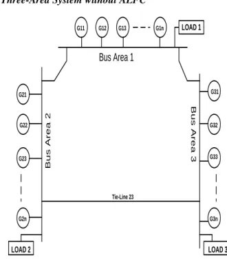
i. Three-Area System without ALFC
G11 G12 G13 G1n G32 G31 G33 G3n G21 G22 G23 G2n LOAD 1 LOAD 2 LOAD 3
Bus Area 1
B u s A r e a 2 B u s A r e a 3 Tie-Line 23Fig. 3. Three-area power generation system
Currently system became too complex with addition of more utilities, which may leads to a condition where supply and demand has got a wide gap [2]. Due to heavy load condition in tie-lines by electric power exchange results in poor damping which may leads to inter-area oscillation. Since the loading conditions are unpredictable, this makes the operation more complex. It has been a topic of concern, right from the beginning of interconnected power system operation. The block diagram of interconnected generating system is shown in fig.3.These three generating areas are interconnected by tie lines.
In this each area has one ALFC loop, they are combined and shown in fig .4.
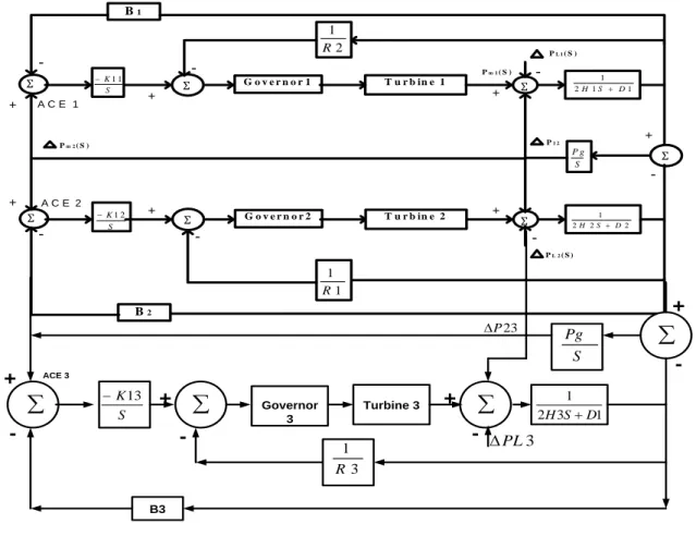
ii Three-Area with ALFC
A “Three-area interconnection” is comprised of regions, or “areas”, that are interconnected by tie-lines. Tie-lines have the benefit of providing inter-area support for abnormal conditions as well as transmission paths for contractual energy exchanges between the areas. The area boundaries are determined by tie-line metering for AGC and contractual billing purposes [3]. In an interconnection where AGC in more than one area is driven solely by a frequency signal, there will be large power oscillations between controlling areas unless regulating actions taken by all areas can be realized simultaneously. Further, the operation of such an interconnection would face a more severe problem if the areas attempting to control frequency had measurement error. An area that measured the frequency at a value higher than others would reduce its generation, while others raised, both attempting to force frequency (as they each measured it to the scheduled value.
Ʃ S K1 1 Ʃ G o v e r n o r 1 T u r b in e 1 Ʃ 1 1 2 1 D S H Ʃ Ʃ G o v e r n o r 2 Ʃ S P g Ʃ S K1 2 T u r b in e 2 2 2 2 1 D S H 1 1 R 2 1 R B1 B2 + + -+ -+ -+ -+ -+ -A C E 1 A C E 2 Pm 2( S ) Pm 1( S ) PL 1( S ) PL 2( S ) P1 2
KS13
Governor 3 Turbine 3 1 3 2 1 D S H B3 3 1 R
23 P 3 PL +
+
+
+
-
-
-ACE 3 S Pg
Fig.4. AGC for three-area operation.
4. Matlab/Simulink results
Case i: Frequency variations without Controller
Fig.5 Simulink model of 3-LFC without Controller
Fig. 6: Simulink result of frequency variation of area-1 without PI controller
Fig. 7: Simulink result of frequency variation of area-2 without PI controller
Fig. 8: Simulink result of frequency variation of area-3 without PI controller
Figure 5 shows the Simulink model of frequency variation in 3-area load frequency control without PI controller. Figure 6 shows the frequency variation in area-1 and frequency variations in area-2 and area-3 are shown in figure 7 and figure 8 respectively.
Fig. 9: Simulink result of frequency variation of tie-line between area-1 and area-2 without PI controller
Fig. 10: Simulink result of frequency variation of tie-line between area-3 and area-2 without PI controller Figure 9 shows the frequency variation in tie-line connecting area-1 and area-2 without PI controller. The frequency response of tie-line connecting area-2 and area-3 without PI controller is shown in figure 10.
Case ii: Frequency variations with PI Controller
Fig.11 Simulink model of 3-LFC with PI Controller
Fig. 12: Frequency variation of area-1 with PI controller
Fig. 13: Frequency variation of area-2 with PI controller
Fig. 14: Frequency variation of area-3 with PI controller Figure 11 shows the Simulink model of frequency variation in 3-area load frequency control with PI controller. Figure 12 shows the frequency variation in area-1 and frequency variations in area-2 and area-3 are shown in figure 13 and figure 14 respectively with PI controller.
Fig. 15: Frequency variation of tie-line between area-1 and area-2 with PI controller
Fig. 16: Frequency variation of tie-line between area-3 and area-2 with PI controller
Figure 15 shows the frequency variation in tie-line connecting area-1 and area-2 with PI controller. The frequency response of tie-line connecting area-2 and area-3 with PI controller is shown in figure 16.
Case iii: Frequency variations with Fuzzy Controller
Fig. 17: Frequency variation of area-1 with Fuzzy controller
Fig. 18: Frequency variation of area-1 with Fuzzy controller
Fig. 19: Frequency variation of area-1 with Fuzzy controller Figure 17 shows the frequency variation in area-1 and frequency variations in area-2 and area-3 are shown in figure 18 and figure 19 respectively with Fuzzy controller.
Fig. 20: Frequency variation of tie-line between area-1 and area-2 with Fuzzy controller
Fig. 21: Frequency variation of tie-line between area-3 and area-2 with Fuzzy controller
Figure 20 shows the frequency variation in tie-line connecting area-1 and area-2 with Fuzzy controller. The frequency response of tie-line connecting area-2 and area-3 with Fuzzy controller is shown in figure 21.
AGC CONTROLLER WITHOUT PI WITH PI WITH FUZZY AREA 1 40 35 20 AREA 2 40 35 20 AREA 3 42 37 20 TIE LINE Connecting area-1 and area-2 40 30 19 TIE LINE Connecting area-1 and area-2 42 37 19
Table 1 load variation
Table I shows the variation in the network with and without PI controller and with Fuzzy controller. The table clearly indicates that without PI controller, the frequency oscillations are more in number and it takes much time to settle down without controller. With fuzzy controller, the settling time still reduces giving more stability to the system.
5 Conclusion
Change in system frequency is one of the most serious issues in power system as it can cause serious threat to the complete system stability. Load changes are very much common in the power system and this change in load causes the frequency to swing. Control measures have to be taken to control the swing of frequency of the system. Without controller, the change in frequency persists for longer time. Conventional PI controller can be adopted to control the swing but still the swing is found to be sustained for longer time period. Fuzzy controller to control the change in frequency effectively damps the oscillations in system frequency. The comparative analysis of the settling time of frequency in the system without controller, with PI control and Fuzzy controller was explained along with the results. Frequency variations in individual load frequency areas were shown along with their tie-line frequency result of three-area system.
References
[1].M.R.I. Sheikh1, R. Takahashi, and J. Tamura “Multi-Area Frequency and Tie-Line Power Flow Control by Coordinated AGC with TCPS” IEEE 6th
International Conference on Electrical and
Computer Engineering.
[2]. Feliachi, A., “On Load Frequency Control in a Deregulated Environment”, IEEE Inter. Conference
on Control Applications, pp.437–441, 15-18 Sept.
1996.
[3]. J. Nanda, A. Mangla and S. Suri, “Some New Findings on Automatic Conventional Controllers”,
IEEE Transactions on Energy Conversion, Vol. 21,
[4]. A.Demiroren, “Application of a Self-Tuning to Automatic Generation Control in Power System Including SMES Units”, ETEP, Vol. 12, No. 2, pp. 101-109, March/April 2002.
[5]. Jiang, H.; Cai, H.; Dorsey, F.; QU, Z., “Toward a Globally Robust Decentralized Control for Large-Scale Power Systems”, IEEE Trans. on Control
System Technology 5 No.3, (1997), 309–319.
[6]. Bengiamin, N. N.; Chan, W. C., “Variable Structure Control of Electric Power Generation”, IEEE Trans.
on PAS, 101 (1982), 376– 380.
[7]. Al-Hamouz, Z. M.; Al-Duwaish, H. N., “A New Load Frequency Variable Structure Controller Using Genetic Algorithms”, Electric Power Systems
Research 55 No. 1 (2000), 1–6.
[8]. R.N. Patel, “Application of Artificial Intelligence for Tuning the Parameters of an AGC”, International
Journal of Mathematical,Physical and Engineering
Sciences, Vol. 1, No. 1, pp. 34-40, May 2007.
[9]. Zeynelgil, H. L.; Demiroren, A.; Sengor, N. S., “The Application of ANN Technique to Automatic Generation Control for Multi-Area Power System”,
Electrical Power and Energy Systems, 24
(2002),545–354.
Biographies:
J. Srinu Naick received his B.E degree
in Electrical & Electronics Engineering from Andhra university Vishakhapatnam AP, India in 2003 and M.Tech with Energetics from NIT Calicut, Calicut, Kerala, India in 2007. He is having 13 years of teaching and research experience. He is currently Associate Professor & Head in the Department of Electrical & Electronics Engineering, PNC&VIET, Repudi, Phringipuram, Guntur, AP, India. His Research interests are in the areas of Power systems Industrial Drives & FACTS Controllers.
K. Chandra Sekhar received his
B.Tech degree in Electrical & Electronics Engineering from V.R.Siddartha Engineering College, Vijayawada, India in 1991 and M.Tech with Electrical Machines & Industrial Drives from Regional Engineering College, Warangal, India in 1994. He Received the PhD, degree from the J.N.T.U, Hyderabad, India in 2008. He is having 17 years of teaching and research experience. He is currently Professor& Head in the Department of Electrical & Electronics Engineering, R.V.R & J.C. College of Engineering Guntur, India. His Research interests are in the areas of Power Electronics, Industrial Drives & FACTS Controllers.