http://www.3com.com/ Part No. DUA1740-0AAA01 Published May 2003
Switch 3812 and Switch 3824
Getting Started Guide
3C17401 3C17400
3Com Corporation 5500 Great America Parkway, Santa Clara, California 95052-8145
Copyright © 2003, 3Com Corporation. All rights reserved. No part of this documentation may be reproduced in any form or by any means or used to make any derivative work (such as translation, transformation, or adaptation) without written permission from 3Com Corporation.
3Com Corporation reserves the right to revise this documentation and to make changes in content from time to time without obligation on the part of 3Com Corporation to provide notification of such revision or change. 3Com Corporation provides this documentation without warranty, term, or condition of any kind, either implied or expressed, including, but not limited to, the implied warranties, terms or conditions of merchantability, satisfactory quality, and fitness for a particular purpose. 3Com may make improvements or changes in the product(s) and/or the program(s) described in this documentation at any time.
If there is any software on removable media described in this documentation, it is furnished under a license agreement included with the product as a separate document, in the hard copy documentation, or on the removable media in a directory file named LICENSE.TXT or !LICENSE.TXT. If you are unable to locate a copy, please contact 3Com and a copy will be provided to you.
UNITED STATES GOVERNMENT LEGEND
If you are a United States government agency, then this documentation and the software described herein are provided to you subject to the following:
All technical data and computer software are commercial in nature and developed solely at private expense. Software is delivered as “Commercial Computer Software” as defined in DFARS 252.227-7014 (June 1995) or as a “commercial item” as defined in FAR 2.101(a) and as such is provided with only such rights as are provided in 3Com’s standard commercial license for the Software. Technical data is provided with limited rights only as provided in DFAR 252.227-7015 (Nov 1995) or FAR 52.227-14 (June 1987), whichever is applicable. You agree not to remove or deface any portion of any legend provided on any licensed program or documentation contained in, or delivered to you in conjunction with, this User Guide.
Unless otherwise indicated, 3Com registered trademarks are registered in the United States and may or may not be registered in other countries.
3Com and the 3Com logo are registered trademarks of 3Com Corporation.
IEEE and 802 are registered trademarks of the Institute of Electrical and Electronics Engineers, Inc.
Intel and Pentium are registered trademarks of Intel Corporation. Microsoft, MS-DOS, Windows, and Windows NT are registered trademarks of Microsoft Corporation. Novell and NetWare are registered trademarks of Novell, Inc. UNIX is a registered trademark in the United States and other countries, licensed exclusively through X/Open Company, Ltd.
Netscape Navigator is a registered trademark of Netscape Communications. JavaScript is a trademark of Sun Microsystems.
All other company and product names may be trademarks of the respective companies with which they are associated.
ENVIRONMENTAL STATEMENT
It is the policy of 3Com Corporation to be environmentally-friendly in all operations. To uphold our policy, we are committed to:
Establishing environmental performance standards that comply with national legislation and regulations. Conserving energy, materials and natural resources in all operations.
Reducing the waste generated by all operations. Ensuring that all waste conforms to recognized environmental standards. Maximizing the recyclable and reusable content of all products.
Ensuring that all products can be recycled, reused and disposed of safely.
Ensuring that all products are labelled according to recognized environmental standards. Improving our environmental record on a continual basis.
End of Life Statement
3Com processes allow for the recovery, reclamation and safe disposal of all end-of-life electronic components. Regulated Materials Statement
3Com products do not contain any hazardous or ozone-depleting material. Environmental Statement about the Documentation
The documentation for this product is printed on paper that comes from sustainable, managed forests; it is fully biodegradable and recyclable, and is completely chlorine-free. The varnish is environmentally-friendly, and the inks are vegetable-based with a low heavy-metal content.
C
ONTENTS
A
BOUTT
HISG
UIDEBefore You Start 7
About Your CD-ROM 7
Conventions 8
Related Documentation 9
Accessing Online Documentation 10
Documentation Comments 10
Product Registration 11
1
I
NTRODUCING THES
WITCH3812
ANDS
WITCH3824
About the Switch 14
Summary of Hardware Features 14
Switch — Front View Detail 15
10BASE-T/ 100BASE-TX/
1000BASE-T Ports 15
SFP Ports 16
LEDs 16
Console Port 17
Switch — Rear View Detail 17
Power Socket 17
Default Settings 18
2
I
NSTALLING THES
WITCHPackage Contents 20
Choosing a Suitable Site 20
Rack-mounting 21
Placing Units On Top of Each Other 23
The Power-up Sequence 23
Powering-up the Switch 23
Choosing the Correct Cables 24
SFP Operation 25
Approved SFP Transceivers 25
Inserting an SFP Transceiver 26
Removing an SFP Transceiver 27
3
S
ETTINGU
PFORM
ANAGEMENTSetting Up Overview 30
IP Configuration 31
Preparing for Management 32
Manually Configuring IP Information 33
Connecting to the Console Port 33
Viewing Automatically Configured IP Information 36
Using 3Com Network Supervisor 36
Connecting to the Console Port 36
Methods of Managing a Switch 39
Command Line Interface Management 39
Web Interface Management 39
SNMP Management 40
Setting Up Command Line Interface Management 40
CLI Management via the Console Port 40
CLI Management over the Network 41
Setting Up Web Interface Management 42
Pre-requisites 42
Web Management Over the Network 42
Setting Up SNMP Management 43
Pre-requisites 43
Default Users and Passwords 43
Changing Default Passwords 44
4
P
ROBLEMS
OLVINGSolving Problems Indicated by LEDs 46
Solving Hardware Problems 47
Solving Communication Problems 48
A
S
AFETYI
NFORMATIONPower Cord Set — Japan 51
Important Safety Information 52 L’information de Sécurité Importante 53 Wichtige Sicherheitsinformationen 55
B
P
IN-
OUTSNull Modem Cable 57
PC-AT Serial Cable 57
Modem Cable 58
RJ-45 Pin Assignments 58
C
T
ECHNICALS
PECIFICATIONSSwitch 3812 and Switch 3824 61
D
T
ECHNICALS
UPPORTOnline Technical Services 63
World Wide Web Site 63
3Com Knowledgebase Web Services 64
3Com FTP Site 64
Support from Your Network Supplier 64
Support from 3Com 65
Internet Support 65
Telephone Support 65
Returning Products for Repair 67
Contacting 3Com Support 68
I
NDEXA
BOUT
T
HIS
G
UIDE
This guide provides all the information you need to install and use the following 3Com switches in their default state.
This guide is intended for use with Switch models:
■ 3C17401 — 3Com Switch 3812 (12-port, Managed Gigabit) ■ 3C17400 — 3Com Switch 3824 (24-port, ManagedGigabit) All procedures described in this guide apply to both models.
The term Switch 3812 and Switch 3824 will be used when referring to the 3Com Switch 3812 (12-port, Managed Gigabit) and
3Com Switch 3824 (24-port, ManagedGigabit).
The term SFP Module and SFP Transceiver are both used to describe the SFP Transceiver.
The guide is intended for use by network administrators who are responsible for installing and setting up network equipment;
consequently, it assumes a basic working knowledge of LANs (Local Area Networks).
Before You Start
This section contains information about the CD-ROM that accompaniesyour Switch.
About Your CD-ROM The CD-ROM also contains the following:
■ Online documentation for the Switch — refer to Related Documentation on page 9 for details.
■ 3Com Network Supervisor — a powerful and easy-to-use network management platform.
8 ABOUT THIS GUIDE
■ A number of other useful applications.
Most user guides and release notes are available in Adobe Acrobat Reader Portable Document Format (PDF) or HTML on the 3Com World Wide Web site:
http://www.3com.com/
Conventions
Table 1 and Table 2 list conventions that are used throughout this guide.Table 1 Notice Icons
Icon Notice Type Description
Information note Information that describes important features or instructions
Caution Information that alerts you to potential loss of data or potential damage to an application, system, or device Warning Information that alerts you to potential personal injury
Table 2 Text Conventions
Convention Description
Screen displays This typeface represents information as it appears on the screen.
Syntax The word “syntax” means that you must evaluate the syntax provided and then supply the appropriate values for the placeholders that appear in angle brackets. Example: To change your password, use the following syntax:
system password <password>
In this example, you must supply a password for <password>.
Commands The word “command” means that you must enter the command exactly as shown and then press Return or Enter. Commands appear in bold. Example:
To display port information, enter the following command:
bridge port detail
The words “enter” and “type”
When you see the word “enter” in this guide, you must type something, and then press Return or Enter. Do not press Return or Enter when an instruction simply says “type.” Keyboard key names If you must press two or more keys simultaneously, the key
names are linked with a plus sign (+). Example: Press Ctrl+Alt+Del
Related Documentation 9
Related
Documentation
In addition to this guide, each Switch documentation set includes the following:
■ Switch Implementation Guide
This guide contains information on the features supported by your Switch and how they can be used to optimize your network. It is supplied in PDF format on the CD-ROM that accompanies the Switch. ■ Switch Management Quick Reference Guide
This guide contains:
■ a list of the features supported by the Switch.
■ a summary of the web interface and command line interface
commands for the Switch.
■ Switch Management Interface Reference Guide
This guide provides detailed information about the web interface and command line interface that enable you to manage the Switch. It is supplied in HTML format on the CD-ROM that accompanies the Switch.
■ Release Notes
These notes provide information about the current software release, including new features, modifications, and known problems.
There are other publications you may find useful, such as:
■ Documentation accompanying 3Com Network Supervisor. This is supplied on the CD-ROM that accompanies the Switch.
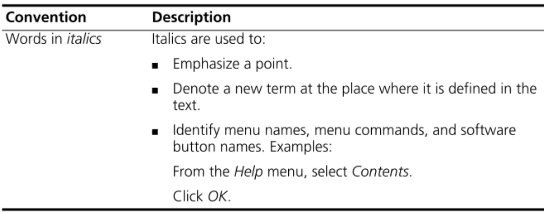
Words in italics Italics are used to: ■ Emphasize a point.
■ Denote a new term at the place where it is defined in the text.
■ Identify menu names, menu commands, and software button names. Examples:
From the Help menu, select Contents. Click OK.
Table 2 Text Conventions (continued)
10 ABOUT THIS GUIDE
Accessing Online Documentation
To access the documentation on the CD-ROM supplied with your Switch, do the following:
1 Insert the CD-ROM into your CD-ROM drive. If your PC has auto-run enabled, a splash screen will be displayed automatically.
2 Select the Documentation section from the contents page.
If the online documentation is to be accessed from a local drive or server, you will need to access the CD-ROM contents via the root directory and copy the files from the CD-ROM to a suitable directory.
■ The HTML Reference Guide is stored in the Docs/reference directory on the CD-ROM. The documentation is accessed using the contents.htm file.
■ The PDF Implementation Guide is stored in the
Docs/implementation directory of the CD-ROM.
3Com recommends that you copy the Docs/reference directory as a whole to maintain the structure of the files.
Documentation
Comments
Your suggestions are very important to us. They will help make our documentation more useful to you. Please e-mail comments about this document to 3Com at:
Please include the following information when commenting: ■ Document title
■ Document part number (on the title page) ■ Page number (if appropriate)
Example:
Part Number DUA1740-0AAA0x
Switch 3812 and Switch 3824 Getting Started Guide Page 21
Product Registration 11
Please note that we can only respond to comments and questions about 3Com product documentation at this e-mail address. Questions related to technical support or sales should be directed in the first instance to your network supplier.
Product
Registration
You can now register your Switch on the 3Com Web site: http://www.3com.com/register/
You will need your product part number (3Cxxxxx), product serial number and date and place of purchase to register your 3Com product.
Registering your product enables you to: process Repair Requests on-line, check the status of your requests at anytime, provides you with important warranty information as well as activating your entitlement to additional service benefits and receive up-to-date information on your product.
1
I
NTRODUCING
THE
S
WITCH
3812
AND
S
WITCH
3824
This chapter contains introductory information about the Switch 3812 and Switch 3824 and how they can be used in your network. It covers summaries of hardware and software features and also the following topics:
■ About the Switch
■ Switch — Front View Detail ■ Switch — Rear View Detail ■ Default Settings
14 CHAPTER 1: INTRODUCINGTHE SWITCH3812 AND SWITCH3824
About the Switch
The Switch is a 10/100/1000 Mbps Ethernet Switch, which consists of 4SFP ports and either:
■ 24 10BASE-T/100BASE-TX/1000BASE-T ports or ■ 12 10BASE-T/100BASE-TX/1000BASE-T ports
The last four 10/100/1000 ports are combination ports. When an SFP port is active it has priority over the 10/100/1000 port of the same number (9 -12 on the 12-port Switch, 21-24 on the 24-port Switch). The corresponding 10/100/1000 port is disabled when an SFP port is active.
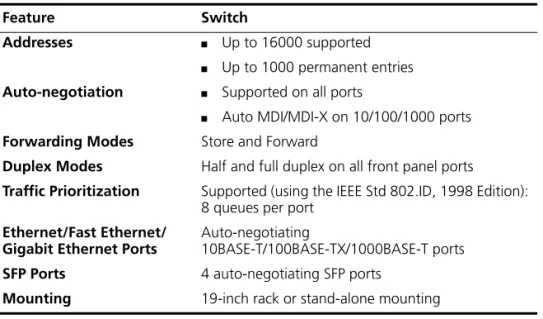
Summary of Hardware Features
Table 3 summarizes the hardware features that are supported by the Switch.
Table 3 Hardware features
Feature Switch
Addresses ■ Up to 16000 supported
■ Up to 1000 permanent entries Auto-negotiation ■ Supported on all ports
■ Auto MDI/MDI-X on 10/100/1000 ports Forwarding Modes Store and Forward
Duplex Modes Half and full duplex on all front panel ports
Traffic Prioritization Supported (using the IEEE Std 802.ID, 1998 Edition): 8 queues per port
Ethernet/Fast Ethernet/ Gigabit Ethernet Ports
Auto-negotiating
10BASE-T/100BASE-TX/1000BASE-T ports SFP Ports 4 auto-negotiating SFP ports
Switch — Front View Detail 15
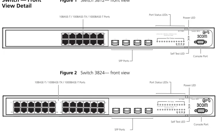
Switch — Front
View Detail
Figure 1 Switch 3812— front view
Figure 2 Switch 3824— front view
WARNING: RJ-45 Ports. These are shielded RJ-45 data sockets. They cannot be used as standard traditional telephone sockets, or to connect the unit to a traditional PBX or public telephone network. Only connect RJ-45 data connectors, network telephony systems, or network telephones to these sockets.
Either shielded or unshielded data cables with shielded or unshielded jacks can be connected to these data sockets.
10BASE-T/ 100BASE-TX/ 1000BASE-T Ports
The Switch has 12 or 24 auto-negotiating 10BASE-T/100BASE-TX/ 1000BASE-T ports configured as Auto MDIX (cross-over). These ports automatically provide the appropriate connection. Alternatively, you can manually set these ports to 10BASE-T half duplex, 10BASE-T full duplex, 100BASE-TX half duplex, 100BASE-TX full duplex, or 1000BASE-T full duplex. The maximum segment length is 100 m (328 ft) over Category 5 twisted pair cable.
7 1 12 6 9 10 7
Yellow/Green Flash = Disabled
Port Status
Link/Activity: Green = 1000M, Yellow = 10/100M, Flash = Activity 11 12
1 2 3 4 5 6
Switch 3812 3C17401 Module Active 9 8 9 10 11 10 11 Power Self Test 12 12 Console Port
10BASE-T / 100BASE-TX / 1000BASE-T Ports Power LED
Self Test LED SFP Ports
Port Status LEDs
21
3C17400
14
Link/Activity: Green = 1000M, Yellow = 10/100M, Flash = Activity
22 23 24
13 1
Module Active
Yellow/Green Flash = Disabled
16
15 1718 19 20 2122
2122 Self Test 24 23 2324 Port Status 4 3
2 5 6 7 8 9 10
Power
1112
Port Status LEDs
Power LED 10BASE-T / 100BASE-TX / 1000BASE-T Ports
SFP Ports
1
13 18 19
7 6
24 12
Console Port Self Test LED
16 CHAPTER 1: INTRODUCINGTHE SWITCH3812 AND SWITCH3824
The default state for 10/100/1000 Mbps ports is auto-negotiation enabled, where the speed, duplex and flow control modes are negotiated. Alternatively, auto-negotiation can be disabled and the speed, duplex and flow control setting can be manually configured.
The last four 10/100/1000 ports are combination ports. When an SFP port is active it has priority over the 10/100/1000 port of the same number (9 -12 on the 12-port Switch, 21-24 on the 24-port Switch). The corresponding 10/100/1000 port is disabled when an SFP port is active.
SFP Ports The four SFP (Small Form Factor Pluggable) ports support fiber Gigabit Ethernet short-wave (SX) and long-wave (LX) SFP Transceivers in any combination. This offers you the flexibility of using SFP transceivers to provide connectivity between the Switch and remote 1000 Mbps workgroups or to create a high capacity aggregated link backbone connection.
The default state for these ports is auto-negotiation enabled, where the speed, duplex and flow control modes are negotiated. As the speed and duplex modes are fixed by the media type, only the flow control is negotiated with the link partner. Alternatively, auto-negotiation can be disabled and the flow control setting can be manually configured.
SFP ports are numbered 9 -12 on the 12-port Switch, 21-24 on the 24-port Switch. When an SFP port is active it has priority over the 10/100/1000 port of the same number. The corresponding 10/100/1000 port is disabled when an SFP port is active.
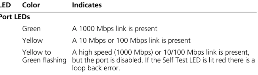
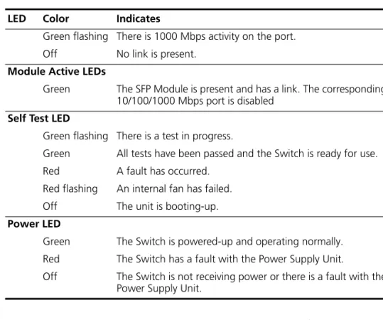
LEDs Table 4 lists LEDs visible on the front of the Switch, and how to read their status according to color. For information on using the LEDs for problem solving, see “Solving Problems Indicated by LEDs” on page 46.
Table 4 LED behavior
LED Color Indicates
Port LEDs
Green A 1000 Mbps link is present
Yellow A 10 Mbps or 100 Mbps link is present Yellow to
Green flashing
A high speed (1000 Mbps) or 10/100 Mbps link is present, but the port is disabled. If the Self Test LED is lit red there is a loop back error.
Switch — Rear View Detail 17
Console Port The console port allows you to connect a terminal and perform remote or local out-of-band management. The console port uses a standard null modem cable and is set to auto-baud, 8 data bits, no parity and 1 stop bit.
Switch — Rear
View Detail
Figure 3 Switch — rear view
Power Socket The Switch automatically adjusts its power setting to any supply voltage in the range 100-240 VAC.
Green flashing There is 1000 Mbps activity on the port.
Off No link is present.
Module Active LEDs
Green The SFP Module is present and has a link. The corresponding 10/100/1000 Mbps port is disabled
Self Test LED
Green flashing There is a test in progress.
Green All tests have been passed and the Switch is ready for use.
Red A fault has occurred.
Red flashing An internal fan has failed.
Off The unit is booting-up.
Power LED
Green The Switch is powered-up and operating normally. Red The Switch has a fault with the Power Supply Unit.
Off The Switch is not receiving power or there is a fault with the Power Supply Unit.
LED Color Indicates
18 CHAPTER 1: INTRODUCINGTHE SWITCH3812 AND SWITCH3824
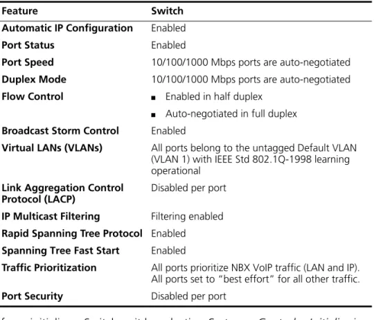
Default Settings
Table 5 shows the default settings for the Switch:Table 5 Default Settings
If you initialize a Switch unit by selecting System > Control > Initialize in the Web interface or by entering system control initialize in the Command Line Interface, the following settings are retained to allow you to connect to and manage the Switch:
■ IP Address ■ Subnet Mask ■ Default Router
Feature Switch
Automatic IP Configuration Enabled
Port Status Enabled
Port Speed 10/100/1000 Mbps ports are auto-negotiated Duplex Mode 10/100/1000 Mbps ports are auto-negotiated Flow Control ■ Enabled in half duplex
■ Auto-negotiated in full duplex Broadcast Storm Control Enabled
Virtual LANs (VLANs) All ports belong to the untagged Default VLAN (VLAN 1) with IEEE Std 802.1Q-1998 learning operational
Link Aggregation Control Protocol (LACP)
Disabled per port IP Multicast Filtering Filtering enabled Rapid Spanning Tree Protocol Enabled Spanning Tree Fast Start Enabled
Traffic Prioritization All ports prioritize NBX VoIP traffic (LAN and IP). All ports set to “best effort” for all other traffic.
2
I
NSTALLING
THE
S
WITCH
This chapter contains the information you need to install and set up the Switch. It covers the following topics:
■ Package Contents ■ Choosing a Suitable Site ■ Rack-mounting
■ Placing Units On Top of Each Other ■ The Power-up Sequence
WARNING: Safety Information. Before installing or removing any components from the Switch or carrying out any maintenance
procedures, you must read the safety information provided in Appendix A
of this guide.
AVERTISSEMENT:Consignes de sécurité. Avant d'installer ou d'enlever tout composant du Switch ou d'entamer une procédure de maintenance, lisez les informations relatives à la sécurité qui se trouvent dans
l'Appendice A de ce guide.
VORSICHT: Sicherheitsinformationen. Bevor Sie Komponenten aus dem Switch entfernen oder dem Switch hinzufuegen oder
Instandhaltungsarbeiten verrichten, lesen Sie die Sicherheitsanweisungen, die in Appendix A (Anhang A) in diesem Handbuch aufgefuehrt sind.
20 CHAPTER 2: INSTALLINGTHE SWITCH
Package Contents
■ Switch unit■ CD-ROM
■ Getting Started Guide (this guide) ■ Management Quick Reference Guide ■ Release Notes
■ Unit Information Labels ■ Warranty Information ■ Power Cord
■ 2 x Mounting brackets ■ 4 x Screws
■ 4 x Rubber feet
Choosing a Suitable
Site
The Switch is suited for use on a desktop, either free standing or
mounted in a standard 19-inch equipment rack. Alternatively, the Switch can be mounted in a wiring closet or equipment room, as an aggregator for other Hubs and Switches. A rack-mounting kit containing two mounting brackets is supplied with the Switch.
CAUTION: Ensure that the ventilation holes are not obstructed.
When deciding where to position the Switch, ensure that: ■ Cabling is located away from:
■ sources of electrical noise such as radios, transmitters and
broadband amplifiers.
■ power lines and fluorescent lighting fixtures
■ The Switch is accessible and cables can be connected easily. ■ Water or moisture cannot enter the case of the Switch.
■ Air flow is not restricted around the Switch or through the vents in the side of the Switch. 3Com recommends that you provide a minimum of 25mm (1in.) clearance.
■ Air temperature around the Switch does not exceed 40 °C (104 °F).
If the Switch is installed in a 19-inch rack or closed assembly its local air temperature may be greater than room ambient temperature.
Rack-mounting 21
■ The air is as free from dust as possible.
■ The unit is installed in a clean, air conditioned environment.
■ No more than eight Switch units are placed on top of one another, if the units are free-standing.
■ The Switch is situated away from sources of conductive (electrical) dust, for example laser printers.
■ The AC supply used by the Switch is separate to that used by units that generate high levels of AC noise, for example air conditioning units and laser printers.
Rack-mounting
The Switch is 1U high and will fit in most standard 19-inch racks.CAUTION:Disconnect all cables from the Switch before continuing. Remove all self adhesive pads from the underside of the Switch if they have been fitted.
To rack-mount your Switch:
1 Place the Switch the right way up on a hard flat surface, with the front facing towards you.
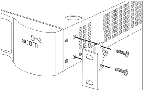
2 Locate a mounting bracket over the mounting holes on one side of the Switch, as shown in Figure 4.
22 CHAPTER 2: INSTALLINGTHE SWITCH
Figure 4 Fitting a bracket for rack-mounting
3 Insert the two screws and tighten with a suitable screwdriver.
You must use the screws supplied with the mounting brackets. Damage caused to the unit by using incorrect screws invalidates your warranty.
4 Repeat steps 2 and 3 for the other side of the Switch.
5 Insert the Switch into the 19-inch rack and secure with suitable screws (not provided). Ensure that ventilation holes are not obstructed.
6 Connect network cabling.
7 Finally place a unit information label on the unit in an easily accessible position. The unit information label shows the following:
■ The 3Com product name of the Switch ■ The 3Com 3C number of the Switch
■ The unique MAC address (Ethernet address) of the Switch ■ The serial number of the Switch
Placing Units On Top of Each Other 23
Placing Units On
Top of Each Other
If the Switch units are free-standing, up to eight units can be placed one on top of the other. If you are mixing a variety of 3Com Switch and Hub units, the smaller units must be positioned at the top.
If you are placing Switch units one on top of the other, you must use the self-adhesive rubber pads supplied. Apply the pads to the underside of each Switch, sticking one in the marked area at each corner. Place the Switch units on top of each other, ensuring that the pads of the upper unit line up with the recesses of the lower unit.
The Power-up
Sequence
The following sections describe how to get your Switch powered-up and ready for operation.
Powering-up the Switch
Use the following sequence of steps to power-up the Switch.
1 Plug the power cord into the power socket at the rear of the Switch. 2 Plug the other end of the power cord into your power outlet. 3 The Power LED lights green and the Self Test LED will flash green for
approximately 30 seconds.
4 The Self Test LED will go off for 45 seconds.
5 When the unit is ready, the Self Test LED lights green.
The Switch powers-up and runs through its Power On Self Test (POST), which takes approximately 60 seconds.
Checking for Correct Operation of LEDs
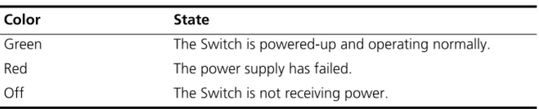
During the Power On Self Test, all ports on the Switch are disabled. When the POST has completed, check the Power and Self Test LEDs to make sure that your Switch is operating correctly. Table 6 shows possible colors for the LED.
Table 6 Power LED colors
Color State
Green The Switch is powered-up and operating normally.
Red The power supply has failed.
24 CHAPTER 2: INSTALLINGTHE SWITCH
Table 7 Self Test LED colors
If there is evidence of a problem, see “Solving Problems Indicated by LEDs” on page 46.
CAUTIONThe Switch has no ON/OFF switch; the only method of connecting or disconnecting mains power is by connecting or disconnecting the power cord.
Choosing the Correct Cables
All of the 10/100/1000 Mbps ports on the Switch are Auto-MDIX, that is they have a cross-over capability. The port can automatically detect whether it needs to operate in MDI or MDIX mode. Therefore you can make a connection to a port with a straight-through (MDI) or a cross-over cable (MDIX).
The Auto-MDIX feature only operates when auto-negotiation is enabled.
If auto-negotiation is disabled, all the Switch ports are configured as MDIX (cross-over). If you want to make a connection to another MDIX port, you need a cross-over cable. Many ports on workstations and servers are configured as MDI (straight-through). If you want to make a connection to an MDI port, you need to use a standard straight-through
cable. See Table 8.
3Com recommends that you use Category 5 twisted pair cable — the maximum segment length for this type of cable is 100 m (328 ft).
Color State
Green The Switch is powered-up and operating normally.
Red POST Test has failed
Red Flashing A fan has failed
Green Flashing There is a test in progress.
SFP Operation 25
Table 8 Cables required to connect the Switch to other devices if
auto-negotiation is disabled
CAUTION:If you want to install the Switch using a Category 5E or Category 6 cable, 3Com recommends that you briefly connect the cable to a grounded port before connecting network equipment. If you do not, the cable’s Electrostatic Discharge (ESD) may damage the Switch’s port. You can create a grounded port by connecting all wires at one end of a UTP cable to an earth ground point, and the other end to a female RJ-45 connector located, for example, on a Switch rack or patch panel. The RJ-45 connector is now a grounded port.
SFP Operation
The following sections describes how to insert an SFP transceiver into anSFP port.
SFP transceivers are hot-insertable and hot-swappable. You can remove them from and insert them into any SFP port without having to power down the Switch.
Approved SFP Transceivers
The following list of approved SFP transceivers is correct at the time of publication.
■ 3CSFP91 SFP (SX) ■ 3CSFP92 SFP (LX)
To access the latest list of approved SFP transceivers for the Switch on the 3Com Corporation World Wide Web site, enter this URL into your internet browser:
http://www.3com.com
Cross-over Cable Straight-through Cable Switch to Switch
(MDIX to MDIX)
✓
✕
Switch to Hub
(MDIX to MDIX)
✓
✕
Switch to PC (NIC)
26 CHAPTER 2: INSTALLINGTHE SWITCH
Inserting an SFP Transceiver
To be recognised as valid, the SFP transceiver must have the following characteristics:
■ 1000BASE-SX or 1000BASE-LX media type:
■ 1000BASE-SX SFP transceiver
Use this transceiver to connect the Switch directly to a multimode fiber-optic cable.
■ 1000BASE-LX SFP transceiver
Use this transceiver to connect the Switch directly to a single-mode fiber-optic cable or to multimode fiber using a conditioned launch cable.
■ Fiber LC connector
If the SFP transceiver is faulty, it will not operate within the Switch. See “Solving Hardware Problems” on page 47.
Use of non-3Com SFPs is not recommended. If the SFP transceiver is invalid it will not be recognised by the Switch.
Use the following sequence of steps to activate the SFP ports:
1 Hold the transceiver so that the fiber connector is toward you and the product label is visible, as shown in Figure 5. Ensure the wire release lever is closed (in the upright position).
2 Gently slide the transceiver into the SFP port until it clicks into place.
CAUTION: SFP transceivers are keyed and can be properly inserted only one way. If the transceiver does not click when you insert it, remove it, turn it over, and reinsert it.
3 Remove the plastic protective cover if fitted. 4 Connect the fiber cable.
SFP Operation 27
Figure 5 Inserting a SFP Transceiver
5 The transceiver connects to the network using a duplex SC connector. Attach a male duplex SC connector on the network cable into the duplex SC connector on the transceiver.
6 Connect the other end of the cable to a device fitted with an appropriate Gigabit Ethernet connection.
7 Check the Module Active LEDs on the front of the Switch to ensure that it is operating correctly. Refer to “LEDs” on page 16 for more information. Removing an SFP
Transceiver
If you wish to remove the transceiver (it is not necessary to power-down your Switch):
1 Disconnect the cable from the transceiver.
2 Move the wire release lever downwards until it is pointing toward you. 3 Pull the wire release lever toward you to release the catch mechanism;
the transceiver will then easily slide out.
21
22
23
24
Product label
Suitable port on host Switch
3
S
ETTING
U
P
FOR
M
ANAGEMENT
Your Switch can operate in its default state, that is, you can install it and it will work straight away (plug-and-play). However, to make full use of the features offered by the Switch, and to change and monitor the way it works, you have to access the management software that resides on the Switch. This is known as managing the Switch.Managing the Switch can help you to improve the efficiency of the Switch and therefore the overall performance of your network. This chapter explains the initial set up of the Switch and the different methods of accessing the management software to manage a Switch. It covers the following topics:
■ Setting Up Overview
■ Manually Configuring IP Information
■ Viewing Automatically Configured IP Information ■ Methods of Managing a Switch
■ Setting Up Command Line Interface Management ■ Setting Up Web Interface Management
■ Setting Up SNMP Management ■ Default Users and Passwords
30 CHAPTER 3: SETTING UPFOR MANAGEMENT
Setting Up
Overview
This section gives an overview of what you need to do to get your Switch set up and ready for management when it is in its default state. The whole setup process is summarized in Figure 6. Detailed procedural steps are contained in the sections that follow. In brief, you need to:
■ Configure IP information manually for your Switch or view the automatically configured IP information
■ Prepare for your chosen method of management
Figure 6 Initial Switch Setup and Management Flow diagram
Plug and Play
Set up In it ia l IP In fo rm a ti o n S e tu p Featur e Management
Power Up the Switch.
IP Information is automatically configured. See page 31
Do you want to manually configure the IP information?
Connect to a front network port and use the
Web Interface or Command Line Interface.
See page 33
How do you want to manage your Switch? See
SNMP See
Command Line Interface
Connect via the console port.
See
Web Interface
Connect over the network via Telnet.
See page 41
Connect over the network.
See
How do you want to view the automatically configured IP information? How do you want to connect to the Switch?
Connect to the console port and use the
Command Line Interface. See page 33
Use 3Com Network Supervisor (3NS).
See page 36
Connect to the console port and use the
Command Line Interface. See page 36
Setting Up Overview 31
CAUTION:To protect your Switch from unauthorized access, you must change all default passwords as soon as possible, even if you do not intend to actively manage your Switch. For more information on default users and changing default passwords, see “Default Users and
Passwords” on page 43.
IP Configuration You can use one of the following methods to allocate IP information to your Switch (essential if you wish to manage your Switch across the network).
Manual IP Configuration
You can choose to configure the IP information yourself. The Switch remembers the information that you enter until you change it again or set the configuration method to Automatic.
You should use the Manual IP configuration method if: ■ you do not have a DHCP server on your network, or
■ you want to remove the risk of the IP address ever changing, or ■ your DHCP server does not allow you to allocate static IP addresses.
(Static IP addresses are necessary to ensure that the Switch is always allocated the same IP information.)
For most installations, 3Com recommends that you configure the Switch IP information manually. This makes management simpler and more reliable as it is not dependent on a DHCP server, and eliminates the risk of the IP address changing.
If you wish to manually enter IP information for your Switch, work through the “Manually Configuring IP Information” section on page 33. Automatic IP Configuration
By default the Switch tries to configure itself with IP information without requesting user intervention. It tries to obtain an IP address from a DHCP server on the network.
When using automatic IP configuration it is important that the IP address of the Switch is static, otherwise you will not know what the IP address is and it will be difficult to manage. Most DHCP servers allow static IP addresses to be configured so that you know what IP address will be allocated to the Switch. Refer to the documentation that accompanies your DHCP server.
32 CHAPTER 3: SETTING UPFOR MANAGEMENT
For a detailed description of how automatic IP configuration operates, please refer to the Implementation Guide on the CD-ROM that accompanies your Switch or on the 3Com Web site.
You should use the automatic IP configuration method if: ■ your network uses DHCP to allocate IP information, or
■ flexibility is needed. If the Switch is re-deployed onto a different subnet, it will automatically reconfigure itself with an appropriate IP address, instead of you having to manually reconfigure the Switch. If you use the automatic IP configuration method, you need to discover the automatically allocated IP information before you can begin
management. Work through the “Viewing Automatically Configured IP Information” section on page 36.
Preparing for Management
Once your Switch’s initial set up is complete you can set up your chosen management method as described in “Methods of Managing a Switch” on page 39.
For detailed information about the specific web interface operations and command line interface commands and problem solving, refer to the “Switch Management Interface Reference Guide” on the CD-ROM that is supplied with the Switch or on the 3Com Web site.
Manually Configuring IP Information 33
Manually
Configuring IP
Information
You can manually configure the Switch IP information in the following way:
■ Connecting to the console port — Connect a workstation using a console cable to the console port of the Switch. You can then manually enter IP information using the command line interface (CLI). Connecting to the
Console Port
To set up your Switch manually you can make a connection to the console port (this example describes a local connection to the console port, rather than a remote one via a modem). You can do this whilst the Switch is offline, that is, before you connect the Switch to a network, or whilst the Switch is online, that is, connected to a network.
Pre-requisites
■ A workstation with terminal emulation software installed, such as Microsoft Hyperterminal. This software allows you to communicate with the Switch via the console port directly.
■ Documentation supplied with the terminal emulation software. ■ A suitable cable:
■ A standard null modem cable — if you are connecting directly to
the console port, or
You can find pin-out diagrams for both cables in Appendix B on page 57.
■ You need to have the following so that you can manually set up the Switch with IP information:
■ IP address ■ subnet mask ■ default gateway
34 CHAPTER 3: SETTING UPFOR MANAGEMENT
Connecting the Workstation to the Switch
1 Connect the workstation to the console port using a standard null modem cable as shown in Figure 7.
Figure 7 Connecting a workstation to the Switch via the console port
To connect the cable:
a Attach the female connector on the cable to the male connector on the console port of the Switch.
b Tighten the retaining screws on the cable to prevent it from being loosened.
c Connect the other end of the cable to one of the serial ports (also known as a COM port) on your workstation.
2 Open your terminal emulation software and configure the COM port settings to which you have connected the cable. The settings should be set to match the default settings for the Switch, which are:
■ 19,200 baud ■ 8 data bits ■ no parity ■ 1 stop bit
■ no hardware flow control
Refer to the documentation that accompanies the terminal emulation software for more information.
Setting Up the Switch with IP Information
You are now ready to manually set up the Switch with IP information using the command line interface.
1 The command line interface login sequence begins as soon as the Switch detects a connection to its console port.
If the login prompt does not begin immediately, press Return a few times until it starts.
Console Port Connection Standard Null Modem Cable
Workstation (with terminal emulation
software installed)
Manually Configuring IP Information 35
2 At the login and password prompts, enter admin as your user name and press Return at the password prompt. If you have logged on correctly, the top-level menu of the command line interface is displayed as shown in the example in Figure 8.
Figure 8 Example top-level command line interface menu
3 At the Select menu option prompt you can either:
■ enter the protocol ip basicConfig command. At the Enter
configuration method prompt enter manual. The screen
prompts you to enter IP information. or
■ enter the gettingStarted command. At the Enter
configuration method prompt enter manual. The screen
prompts you to enter IP information.
4 Enter the IP address, subnet mask, and gateway IP address for the Switch. The screen displays a summary of the information entered.
If using the gettingStarted command you will then be prompted to enter system information, change passwords, and then given the option to carry out advanced configuration.
The initial set up of your Switch is now complete and the Switch is ready for you to set up your chosen management method. See “Methods of Managing a Switch” on page 39.
If you do not intend to use the command line interface via the console port to manage the Switch, you can disconnect the serial cable and close the terminal emulator software.
36 CHAPTER 3: SETTING UPFOR MANAGEMENT
Viewing
Automatically
Configured IP
Information
If you allow the Switch to automatically configure its own IP information you need to discover and view the IP information before you can begin to manage the Switch. You can discover the IP information in two ways: ■ Using 3Com Network Supervisor — This application will auto-discover
the Switch and display the automatically allocated IP information assigned to the Switch.
■ Connecting to the Console Port — Connect a workstation using a console cable to the console port of the Switch. You can then view the IP information automatically assigned to the Switch using the
command line interface (CLI). Using 3Com Network
Supervisor
You can use the 3Com Network Supervisor applicationprovided on the CD-ROM that accompanies your Switch to discover the automatically allocated IP information.
1 Connect your Switch to the network.
2 Power-up the Switch and wait for two minutes.
3 Launch 3Com Network Supervisor and run the Auto-discovery wizard. 3Com Network Supervisor will auto-discover the new Switch and display the IP information that has been automatically allocated to the Switch.
Most DHCP servers allow static IP addresses to be configured so that you know what IP address the Switch will be given. Refer to the
documentation that accompanies your DHCP server.
Connecting to the Console Port
Alternatively, you can view the automatically configured IP information via the command line interface (CLI) through a connection to the console port. (This example describes a local connection to the console port, rather than a remote one via a modem.)
Pre-requisites
■ A workstation with terminal emulation software installed, such as Microsoft Hyperterminal. This software allows you to communicate with the Switch via the console port directly, or through a modem. ■ Documentation supplied with the terminal emulation software. ■ A suitable cable:
■ A standard null modem cable — if you are connecting directly to
Viewing Automatically Configured IP Information 37
You can find pin-out diagrams for the cable in Appendix B on page 57.
■ A Category 5 twisted pair Ethernet cable with RJ-45 connectors to connect your Switch to the network.
Connecting the Workstation to the Switch
1 Connect the workstation to the console port using a standard null modem cable as shown in Figure 9.
Figure 9 Connecting a workstation to the Switch via the console port
To connect the cable:
a Attach the female connector on the cable to the male connector on the console port of the Switch.
b Tighten the retaining screws on the cable to prevent it from being loosened.
c Connect the other end of the cable to one of the serial ports (also known as a COM port) on your workstation.
2 Open your terminal emulation software and configure the COM port settings to which you have connected the cable. The settings should be set to match the default settings for the Switch, which are:
■ 19,200 baud ■ 8 data bits ■ no parity ■ 1 stop bit
■ no hardware flow control
Refer to the documentation that accompanies the terminal emulation software for more information.
Console Port Connection Standard Null Modem Cable
Workstation (with terminal emulation
software installed)
38 CHAPTER 3: SETTING UPFOR MANAGEMENT
Viewing IP Information via the Console Port
You are now ready to view the automatically allocated IP information using the command line interface.
1 Connect your Switch to the network using an Ethernet cable. As soon as a network connection is made the Switch begins the automatic IP configuration process.
The automatic IP configuration process usually completes within one minute.
2 The command line interface login sequence begins as soon as the Switch detects a connection to its console port.
If the login prompt does not begin immediately, press Return a few times until it starts.
3 At the login and password prompts, enter admin as your user name and press Return at the password prompt. If you have logged on correctly, the top-level menu of the command line interface is displayed as shown in the example in Figure 10.
Figure 10 Example top-level command line interface menu
4 At the Select menu option prompt enter the protocol ip interface summary command. A summary of the automatically allocated IP information is displayed. Make a note of the Network IP Address.
The initial set up of your Switch is now complete and the Switch is ready for you to set up your chosen management method. See “Methods of Managing a Switch” on page 39.
If you do not intend to use the command line interface via the console port to manage the Switch, you can logout, disconnect the serial cable and close the terminal emulator software.
Methods of Managing a Switch 39
Methods of
Managing a Switch
Once you have completed the initial set up of your Switch, you can decide how you wish to manage the Switch. You can use one of the following methods:
■ Command line interface management ■ Web interface management
■ SNMP management
Command Line Interface Management
Each Switch has a limited command line interface (CLI) that allows you to manage the Switch from a workstation, either locally via a console port connection (see Figure 11), or remotely over the network (see Figure 12).
Figure 11 CLI management via the console port
Figure 12 CLI management over the network
Refer to “Setting Up Command Line Interface Management” on page 40.
Web Interface Management
Each Switch has an internal set of web pages that allow you to manage the Switch using a Web browser remotely over an IP network (see Figure 13).
Console Port Connection Standard Null Modem Cable
Workstation (with terminal emulation
software installed)
40 CHAPTER 3: SETTING UPFOR MANAGEMENT
Figure 13 Web interface management over the network
Refer to “Setting Up Web Interface Management” on page 42.
SNMP Management You can manage a Switch using any network management workstation running the Simple Network Management Protocol (SNMP) as shown in Figure 14. For example, you can use the 3Com Network Supervisor software that is provided on the CD-ROM that accompanies your Switch.
Figure 14 SNMP management over the network
Refer to “Setting Up SNMP Management” on page 43.
Setting Up
Command Line
Interface
Management
This section describes how you can set up command line interface management using a local console port connection or over the network.
CLI Management via the Console Port
To manage a Switch using the command line interface via the local console port connection:
1 Ensure you have connected your workstation to the console port correctly as described in “Connecting to the Console Port” on page 33.
2 Your Switch is now ready to continue being managed and/or configured through the CLI via its console port.
Setting Up Command Line Interface Management 41
CLI Management over the Network
To manage a Switch using the command line interface over a network using Telnet:
1 Ensure you have already set up the Switch with IP information as described in “Setting Up Overview” on page 30.
2 Check that you have the IP protocol correctly installed on your
management workstation. You can check this by trying to browse the World Wide Web. If you can browse, the IP protocol is installed. 3 Check you can communicate with the Switch by entering a ping
command at the DOS prompt in the following format: c:\ ping xxx.xxx.xxx.xxx
(where xxx.xxx.xxx.xxx is the IP address of the Switch)
If you get an error message, check that your IP information has been entered correctly and the Switch is powered up.
4 To open a Telnet session via the DOS prompt, enter the IP address of the Switch that you wish to manage in the following format:
>telnet xxx.xxx.xxx.xxx
(where xxx.xxx.xxx.xxx is the IP address of the Switch)
If opening a Telnet session via third party software you will need to enter the IP address in the format suitable for that software.
5 At the login and password prompts, enter admin as your user name and press Return at the password prompt (or the password of your choice if you have already modified the default passwords).
If the login prompt does not display immediately, press Return a few times until it starts.
6 If you have logged on correctly, the top-level menu of the command line interface for the Switch you wish to manage is displayed as shown in Figure 8 on page 35.
42 CHAPTER 3: SETTING UPFOR MANAGEMENT
Setting Up Web
Interface
Management
This section describes how you can set up web interface management over the network.
Pre-requisites ■ Ensure you have already set up the Switch with IP information as described in “Setting Up Overview” on page 30.
■ Ensure that the Switch is connected to the network using a Category 5 twisted pair Ethernet cable with RJ-45 connectors.
■ A suitable Web browser. Choosing a Browser
To display the web interface correctly, use one of the following Web browser and platform combinations:
Table 9 Supported Web Browsers and Platforms
For the browser to operate the web interface correctly, JavaScript™ and Cascading Style Sheets must be enabled on your browser. These features are enabled on a browser by default. You will only need to enable them if you have changed your browser settings.
Web Management Over the Network
To manage a Switch using the web interface over an IP network: 1 Check that you have the IP protocol correctly installed on your
management workstation. You can check this by trying to browse the World Wide Web. If you can browse, the IP protocol is installed. 2 Check you can communicate with the Switch by entering a ping
command at the DOS prompt in the following format: c:\ ping xxx.xxx.xxx.xxx
(where xxx.xxx.xxx.xxx is the IP address of the Switch)
If you get an error message, check that your IP information has been entered correctly and the Switch is powered up.
Windows 98
Windows NT 4
Windows
2000 Windows XP
Solaris 2.6
Netscape 7
✓
✓
✓
✓
✕
Internet Explorer 5.5
Setting Up SNMP Management 43
3 Open your web browser and enter the IP address of the Switch that you wish to manage in the URL locator, for example, in the following format: http://xxx.xxx.xxx.xxx
4 At the login and password prompts, enter admin as your user name and press Return at the password prompt (or the password of your choice if you have already modified the default passwords).
5 Click on the Device View button to display the web management options.
Setting Up SNMP
Management
Any network management application running the Simple Network Management Protocol (SNMP) can manage a Switch if:
■ The correct Management Information Bases (MIBs) are installed on the management workstation.
■ The management workstation is connected to the Switch using a port in VLAN 1 (the Default VLAN). By default, all ports on the Switch are in VLAN 1.
You can use the 3Com Network Supervisor application that is provided on the CD-ROM that accompanies your Switch to provide SNMP
management for your Switch. If you use 3Com Network Supervisor it automatically loads the correct MIBs and necessary files onto your workstation.
Pre-requisites ■ Documentation supplied with the SNMP network management application software.
To manage your Switch using an SNMP network management
application, you need to specify SNMP community strings for the users defined on the Switch. You can do this using the web management interface — refer to the command line interface section of the “Switch Management Interface Reference Guide” for more information.
Default Users and
Passwords
If you intend to manage the Switch using the web interface or the command line interface, or to change the default passwords, you need to log in with a valid user name and password. The Switch has two default user names, and each user name has a different password and level of access. These default users are listed in Table 10.
44 CHAPTER 3: SETTING UPFOR MANAGEMENT
CAUTION:To protect your Switch from unauthorized access, you must change the two default passwords as soon as possible, even if you do not intend to actively manage your Switch
Table 10 Default Users
Use the admin default user name (no password) to login and carry out initial Switch setup.
Changing Default Passwords
You can change the default passwords using either: ■ The gettingStarted command on the CLI, or
■ The Security > Device > User > Modify operation on the web interface.
For more information about default users and passwords, refer to the “Switch Management Interface Reference Guide” on the Switch CD-ROM.
User Name
Default
Password Access Level
monitor monitor monitor — the user can view all manageable parameters, but cannot change any manageable parameters
admin (no
password)
security — the user can access and change all manageable parameters
4
P
ROBLEM
S
OLVING
This chapter helps you to diagnose and solve problems you may have with the operation of your Switch. There is also an explanation of IP addressing.
The topics covered are:
■ Solving Problems Indicated by LEDs ■ Solving Hardware Problems
■ Solving Communication Problems ■ Solving Software Upgrade Problems
If you experience a problem that is not listed here, it may be included in the Support section of the Switch Management Interface Reference Guide on the CD-ROM that accompanies your Switch.
46 CHAPTER 4: PROBLEM SOLVING
Solving Problems
Indicated by LEDs
If the LEDs on the Switch indicate a problem, refer to the list of suggested solutions below.
The Power LED does not light
Check that the power cable is firmly connected to the Switch and to the supply outlet. If the connection is secure and there is still no power, you may have a faulty power cord or an internal fault. Check the power cord by:
■ testing it in another device
■ connecting a working power cord to the ‘problem’ device Then contact your supplier for advice.
On powering-up, the self test LED remains off for 45 seconds.
On powering-up, the Self Test LED lights red Either:
■ The Switch unit has failed its Power On Self Test (POST) because of an internal problem. Contact your supplier for advice.
or
■ A port has failed and has been automatically disabled. You can verify this by checking that the Port Status LED is flashing Green/Yellow. This could be due to loop back failure. If a port fails the Switch passes its Power On Self Test and continues to operate normally.
On powering-up, the self test LED remains off for 45 seconds.
The Self Test LED is flashing red An internal fan has malfunctioned: 1 Power off the unit
2 Check that all air vents are not obstructed
3 If the air vents are not obstructed please contact your reseller. A Port Status LED is flashing green/yellow
The port has failed and has been automatically disabled. The Switch passes its Power On Self Test and continues to operate normally, even if one or more ports are disabled.
Solving Hardware Problems 47
A link is connected and yet the Status LED for the port does not light
Check that:
■ The Switch and the device at the other end of the link (or cable) are connected securely.
■ The devices at both ends of the link are powered-up. ■ The quality of cable is satisfactory.
■ Auto-negotiation settings are the same at both ends.
Auto-negotiation problems will occur with 10BASE-T, 100BASE-TX or 1000BASE-T where auto-negotiation is disabled and incorrect cables are being used (cross-over or straight).
Auto-negotiation problems will occur with fiber if:
■ The Receiver (RX) and Transceiver (TX) cable connectors are
swapped.
■ Fibers are broken.
■ Auto-negotiation differs at either end (a link appears at the ‘fixed’
end and not at the auto-negotiation end).
Solving Hardware
Problems
In the rare event of your Switch unit experiencing a hardware failure, refer to the list of suggested solutions below.
A fan failure warning message is received
Your Switch has a fan monitoring system that will generate fan failure warning messages. Fan failure could potentially reduce the lifetime of the Switch. The monitoring system polls the fan status at periodic intervals while the unit is powered up.
If one fan has failed in the Switch, a warning message will be generated in the following way:
■ RMON Trap — If configured, an RMON trap is generated and sent to the management workstation.
For further information about RMON, refer to “Chapter 7: Status Monitoring and Statistics” in the Switch Implementation Guide supplied in PDF format on the CD-ROM that accompanies the Switch.
48 CHAPTER 4: PROBLEM SOLVING
If more than one fan has failed in the Switch, a warning message will generate a RMON Trap.
If a fan failure warning message is generated: 1 Power off the unit.
2 Check that the air vents are not obstructed.
3 Power cycle the unit. To do this, remove and reconnect the AC mains supply.
4 If another fan failure warning message is generated via the RMON trap, return the unit.
Solving
Communication
Problems
If you experience communication problems with the Switch, ensure that: ■ The Switch IP address has been configured as described in Chapter 3. ■ If the Switch is separated from your management application by a
router, ensure that the default gateway IP address within the Switch is the same as the IP address of the router.
■ The Switch’s IP address has been entered correctly in your network management application (such as 3Com Network Supervisor). The following is a brief overview of IP addressing, and how to obtain a registered IP address.
IP Addressing
To be managed correctly, each device on your network (for example a Switch or Hub) must have a unique IP address. IP addresses have the format n.n.n.n where n is a decimal number between 0 and 255. An example IP address is 192.168.100.8.
The IP address is split into two parts:
■ The first part (‘192.168.100’ in the example) identifies the network on which the device resides
■ The second part (‘.8’ in the example) identifies the device within the network
Solving Software Upgrade Problems 49
If your network has a connection to the external IP network, that is, you access the Internet, you must apply for a registered IP address.
How do you obtain a registered IP Address?
The IP registration system ensures that every IP address used is unique; if you do not have a registered IP address, you may be using an identical address to someone else and your network will not operate correctly. InterNIC Registration Services is the organization responsible for supplying registered IP addresses. The following contact information is correct at time of publication:
World Wide Web site: http://www.internic.net
If your IP network is internal to your organization only, that is, you do not access the Internet, you may use any arbitrary IP address as long as it is not being used by another device on your network. 3Com suggests you use addresses in the range 192.168.0.0 to 192.168.255.255 with a subnet mask of 255.255.255.0.
These suggested IP addresses are part of a group of IP addresses that have been set aside specially for use ‘in house’ only.
Solving Software
Upgrade Problems
You can upgrade the management software of the Switch by using the
System > Control > Software Upgrade operation in the Web Interface, or the system control softwareUpgrade command in the
command line interface. For details on these options, refer to the Management Interface Reference Guide supplied in HTML format on the CD-ROM that accompanies your Switch.
If you have problems with your software upgrade, refer to the Problem Solving section in the Management Interface Reference Guide.
A
S
AFETY
I
NFORMATION
You must read the following safety information before carrying out any installation or removal of components, or any maintenance procedures on the Switch.
WARNING: Warnings contain directions that you must follow for your personal safety. Follow all directions carefully.
You must read the following safety information carefully before you install or remove the unit.
AVERTISSEMENT: Les avertissements présentent des consignes que vous devez respecter pour garantir votre sécurité personnelle. Vous devez respecter attentivement toutes les consignes.
Nous vous demandons de lire attentivement les consignes suivantes de sécurité avant d’installer ou de retirer l’appareil.
VORSICHT: Warnhinweise enthalten Anweisungen, die Sie zu Ihrer eigenen Sicherheit befolgen müssen. Alle Anweisungen sind sorgfältig zu befolgen.
Sie müssen die folgenden Sicherheitsinformationen’ sorgfältig durchlesen, bevor Sie das Gerät installieren oder ausbauen.