Satellite Communications
Broadband channel simulator for robust
satellite link designs
Impairments in broadband satellite communications signals occur, but by
simulating these impairments in a real-time environment, a broadband
communications system design can be proven and optimized prior to
production.
By Jack Anderson
n the real estate market, there are three
I
priorities: location, location and location. In the broadband satellite communications arena, the top three priorities would be data, data and data. In mainstream, down-to-earth communications systems such as DSL, cable modems, WiFi and even cellular, high-speed access to information is fast becoming a must-have and is highly addictive. Anyone who has worked from a dial-up modem connection after getting accustomed to broadband knows what this means.Data rates in satellites are an element of the overall capacity of the satellite. Multiple transponders, transponder bandwidths, car-rier frequency, transponder receive sensitiv-ity, transponder transmit power, communi-cation signaling schemes, and communicommuni-cation data structures all contribute to the capacity equation. A recent industry study indicates that from 1990 to 2002, the average number of equivalent 36 MHz transponders on geo-synchronous satellites increased from 26 to 48 transponders per satellite launched. This same study showed that the average power levels for these satellites increased by 350%, the design life increased from 10 years to almost 14 years, and the satellite size and complexity increased by factors of 2 to 5 times1. Shin Satellites’ iPSTAR, a new
gen-eration of Internet Protocol (IP) satellites, boasts a total capacity of 40 Gbps, which they claim is a 40 times increase over current satellite capability.2 Hughes Network
Sys-tems’ SPACEWAY has a 800 Mbps down-link data rate per spot beam3 and includes
sophisticated on-board processing, dynami-cally switched spot beams, bandwidth-on-demand allocation and TDMA formatting. SPACEWAY will set the bar for fielded com-mercial satellite technology when launched this summer.
The advanced broadband communications satellites being developed today are costly to design, manufacture and deploy. Most will be placed in geosynchronous (GEO) orbits. They require a significant initial capital out-lay years before they are placed into service
and start to see revenue returns. To this extent, the satellite designers try to maximize payload capacity, so that once in service, the satellite operator will achieve the greatest revenue stream. It is part of the fundamental return-on-investment (ROI) business
calcu-lation—the more capacity, the more poten-tial sales.
In an ideal world, all design parameters would be maximized to obtain the highest possible capacity and performance. In the real world, real trade offs in these parameters
Figure 1. Notional diagram of satellite communication link.
18 www.rfdesign.com April 2004
must be carefully considered and modeled to ensure design goals are achieved. For ex-ample, as the carrier frequencies go up, the available bandwidth increases, but available technology to generate the downlink power decreases. And while higher bandwidths will support faster data rates, the lower power decreases the signal-to-noise ratio (SNR) at the receiver, which will limit the effective data rate achievable through the system. The trend in downlinks moving from L band (2.4 GHz) and C band (6 GHz) to Ku band (14 GHz) and Ka band
(30 GHz) also bring with it the challenges of increased atmo-spheric attenuation, pronounced rain fade and scintillation.
In addition to the move to Ku and Ka bands, other trends in the industry include:
■Increased transponder bandwidths from standard 36 MHz to 72 MHz and beyond.
■Changes in signal modulations from standard BPSK and QPSK to 8PSK, QAM, concentric PSK or Star QAM, and even OFDM4.
■Frequency-hopped carriers.
■More robust coding, including turbocodes.
So what does this mean to the
satellite design engineer?
As advanced communications satellite de-signs push the envelope to maximize data rates and capacities, they can leave little mar-gin for error. Any parameter or real-world effect not analyzed or accounted for could offer surprises that lead to degraded perfor-mance and corresponding loss of revenue. The converse is that the system may be over-designed, putting too much margin in each parameter due to unknowns or worst-case estimates, adding unnecessary cost in price, components, weight, and complexity. Many parameters and variables need to be consid-ered, and the entire communications channel must be analyzed—both satellite and ground terminals. Figure 1 is a notional diagram of a complete satellite link for a traditional “bent pipe” configuration, showing the major com-ponents. The satellite portion shows only one transponder slice. In reality, from 30 to 50 transponders could be on the satellite.
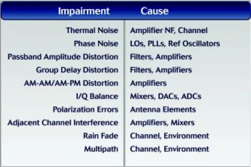
Each component has its non-ideal perfor-mance, which can lead to an overall degrada-tion in the system. A representative list of degradations, also called impairments, along with the component causing the impairment is shown in Table 1. The first and most basic impairment is thermal noise. With the carrier power it sets the carrier-to-noise ratio (CNR) or SNR in a channel. When SNR and band-width are specified, Shannon’s law defines the maximum channel capacity in bits per second, a limit that is never achieved. Many papers have been written on this subject, and exhaustive theoretical studies have been per-formed to predict the raw bit error rate (BER) of the communications system as a function of modulation, coding and SNR.
Not as well understood but important to
the overall system performance and capacity are the other impairments listed in Table 1. As the broadband system designs extend the bandwidths up to hundreds of megahertz, move to higher-order modulations, and apply powerful error correction schemes, they push the performance close to the digital boundary between low error rates and unacceptably high error rates, making it critical to accu-rately simulate all impairments realistically in the channel to ensure an optimal design.
Design simulation and test tools
Several approaches are available to the satellite system designers to aid in the design process. Computer modeling and simulation tools provide the designers insights into over-all performance, with models that take into account a number of channel impairments. These are used to develop the basic designs and to estimate performance. This software runs on desktop computers and advanced workstations. Accurate results may require hours of computing time, even on the fastest processors, leading to a limitation in the num-ber of cases simulated and the combination of impairments tried. There is also the chance that the models do not accurately reflect the real world.
At the other extreme, experimental satel-lites have been built and launched to test new communications technology and concepts in
the real world using real hardware and soft-ware. These satellites include ACT, Artemis, Kopernikus, N-Star, Superbird, and Italsat F1. Satellites are costly to produce, but have been valuable test beds in refining technology and defining techniques for the broadband satellites designs of today. While satellites are the pinnacles of real-world test beds, their performance is fixed by design, leaving little flexibility to change any specification on demand. As such, impairments cannot easily be modified to test the effects on overall system performance.
Satellite channel simulators combine the best of both worlds in test and simulation, offering the advantages of accuracy and real time. One example is the Celerity CS80000 Broadband Channel Simulator (BCS) family
from Aeroflex, shown in Figure 2. These simulators are laboratory instruments that cre-ate real-world channels with impairments in a controlled, accurate and repeatable manner. Because these are real-time systems with broadband RF inputs and outputs, actual hard-ware terminals can be used during testing. This real-time testing allows a much larger number of test cases to be run than with the software models, so that more exhaustive testing is achieved. The features are:
■ Stable, repeatable simulation with de-fined controllable impairments.
■ Real-time and full-bandwidth channels that support real hardware and fast test times.
■ Worst-case scenario simulations with any combination of impairments.
■ Lab instrument that minimizes costly drive testing or real satellite test times.
Other development test tools include Broadband Signal Generators (BSG) and Broadband Signal Analyzers (BSA). While not channel simulators, these instruments gen-erate realistic satellite signals and environ-ments with impairenviron-ments as well as record and analyze signal channel performance.
Broadband channel simulators:
The basics
Figure 3 shows the major functions of an ideal broadband channel simulator. These functions closely emulate the actual channel
Figure 2. Celerity CS80072 broadband channel simulator.
Figure 3. Major functions of an ideal broadband channel simulator.
Accurate results may require hours of computing
time, even on the fastest processors, leading to a
limitation in the number of cases simulated and
the combination of impairments tried.
and impairments, plus offer the speed, accu-racy, and flexibility to quickly try many com-binations of settings.
Channel simulators must have sufficient
bandwidth and dynamic range to meet the
channel requirement. Without intentionally added impairments, they should faithfully pass the signals with minimum degradation. For many satellite systems, the minimum dynamic range for the simulator would be about 40 dB. For satellite communications systems that use advanced modulations, higher dy-namic ranges may be required. Testing with Aeroflex channel simulators have shown that
modulations up to 64 QAM can be success-fully used with 40 dB dynamic ranges with minimal degradation.
Channel delay is also important. Long
delays are a key part of the satellite channel.
For geosynchronous satellites, the 22,300-mile average distance between the earth ter-minal and the satellite causes a 120-millisec-ond delay in uplink or downlink signals. If one hop (up and back) or two hop links are to be modeled, delays up to 600 milliseconds are needed. This is important when testing IP schemes to ensure that they work with the long satellite delays, especially in bent pipe
configurations. Standard terrestrial IPs that use carrier sense multiple-access/collision detection (CSMA/CD) will not work if the delays are too long to resolve collisions, and must be modified and tested for GEO satellite use.
Dynamic delay and dynamic Doppler are
required to simulate satellite or ground mo-tion. Geosynchronous satellites are not sta-tionary but are positioned with a slight offset from the equatorial plane (inclination), so their relative motion as viewed from the earth is a long figure eight moving mostly north and south over a 24-hour period. This mo-tion causes delay and Doppler shifts in the signal. The delay change can be as much as 1 millisecond for a 28 inclination. The Dop-pler frequency shift depends on the carrier frequency, but is approximately 1 kHz with a Ku-band carrier for a 28 inclination. Low earth orbit (LEO) and medium earth orbit (MEO) satellites exhibit far greater dynamic delay and Doppler, as they move across the sky from horizon to horizon with each pass. Iridium LEO satellites operate at alti-tudes of about 485 miles, orbiting the earth every 100 minutes. Delay changes of 2 milliseconds to more than 5 milliseconds occur when in view, with corresponding high Dop-pler frequency shifts. Dynamic delay is important in a channel simulator because the delay change actually shifts the symbol timing of digital sig-nals, forcing the terrestrial terminal’s receiver-demodulator to buffer signals in memory to operate with a fixed bit rate out-put network. Too much delay change can cause these buffers to overflow or under-flow, with a resultant dropping of data. A key requirement in a channel simulator is the ability to change delay dynamically without glitching the phase of the signal. Tools for creating and controlling the delay and
Figure 4. Constellation of 16 QAM signal with 50 dB SNR and with 20 dB SNR.
Figure 5. Phase noise effects. Figure 6. Passband amplitude and phase variation effects on 16QAM signal (without equalization).
Testing with Aeroflex channel simulators have
shown that modulations up to 64 QAM can be
successfully used with 40 dB dynamic ranges
22 www.rfdesign.com April 2004
Doppler scenario files over a 24-hour period are also important.
Two synchronous channels should be
avail-able in the channel simulator, with indepen-dent dynamic delay and Doppler controls. Many communications links operate in duplex mode, where the two terminals are interacting. Two simulator channels allow the flow of data in both directions to support this mode.
Broadband channel simulators:
Advanced capabilities with
realistic impairments
Now that the simulator basics are cov-ered, the number of impairments available and the realism and control of the impair-ments prove the simulator’s real value to the developer. The ideal simulator should simu-late as many of the impairments shown in
Table 1 as possible. Thermal noise is a good starting point, as its effects on system perfor-mance are well understood. But other factors such as I/Q imbalance, phase noise, phase and amplitude distortion, gain linearity, chan-nel loading, multipath, and interference fur-ther degrade the real-world system perfor-mance, and must be considered to optimize designs and avoid performance pitfalls.
Thermal noise has already been discussed
as to the impact it has in a communications channel. Simulators need to have statistically accurate additive white Gaussian noise (AWGN) generators that cover the channel bandwidth with precise control of noise power densities. This is summed into the channel, and allows accurate SNRs to be created and BERs to be measured. Figure 4 shows a constellation plot for an ideal 16 QAM signal
Figure 7. Realistic channel loading and interference simulation using CS25040 BSG.
operating at 50 Msymbols per second and 50 dB SNR, plus a constellation with the same signal with a 20 dB SNR. The noise causes the tight cluster of points designating a symbol to spread out, increasing the prob-ability that a decision error will be made.
Phase noise, like thermal noise, is
un-avoidable in communications systems and occurs whenever frequency devices are used. Phase noise is seen as sidebands around a carrier and is often measured in 1 Hz to 1 MHz offsets. The higher RF carriers, faster time bases, and wider loop bandwidths used for the broadband systems generate higher phase noise with continuous and spurious phase noise distributions. Figure 5 shows the constellation plot of the16 QAM with phase noise starting at -40 dBc/Hz 100 Hz from carrier and tailing off to -90 dBc/Hz 1 MHz from carrier. Simulators, such as the CS80072, with precision control of phase noise distributions allow communications links to have the communication channel’s phase noise specification tested and validated.
With broadband RF components, it is dif-ficult to maintain pass-band amplitude flatness and phase linearity over the signal bandwidth.
Deviations in flatness and phase linearity
(also represented as group delay distortion) will degrade the com-plex broadband signals. Equalization is almost always applied as part of the demodulation process to minimize these effects. The equal-izer designs of broadband systems can be con-firmed using the channel simulator. Figure 6 shows the effects of 2 dB of passband ripple on the constellation of the 16 QAM signal, and the effects of 108 of passband phase deviation on the constellation.
Broadband satellites support multiple broadband signals in the channel, separated either in time (TDM), frequency (FDM), or both. Gain transfer distortions that include AM/AM and AM/PM distortion can degrade the system performance by causing multiple-carrier intermodulation and signal distortion. Traveling wave tube amplifiers (TWTA), a common choice for the high-power downlink transmit amplifier in satellites, can have sig-nificant gain transfer distortion even with linearizers. This distortion is the main reason why traditional satellite modulations are lim-ited to QPSK or OQPSK. Channel simula-tors that simulate AM/AM and AM/PM would allow development and testing of new modu-lation techniques in advanced communica-tions channels.
Simulators that inject broadband channel
loading and interference, such as that shown
in Figure 7, can uncover intermodulation problems as well as test for receiver selectiv-ity and adjacent channel interference.
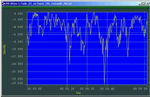
Figure 8. Received power over 60 seconds with a Ricean simulator module.
Simulators need to have statistically accurate additive white
Gaussian noise (AWGN) generators that cover the channel
Simulators can also add co-channel interfer-ence that falls on top of the signal of interest to simulate cross polarization leakage. The multiple signal environment used for channel loading shown in Figure 7 was created using Aeroflex’s CS25040 Broadband Signal and Environment Generator, which can generate up to 160 MHz bandwidth environments.
Ricean multipath effects result when the
direct signal path and a number of reflected paths, with the proper simulated signal im-pairments, are combined at the receiver. This causes fluctuations in the received signal power (and phase and passband flatness de-pending on the severity). Higher frequency bands and directional antennas tend to limit these effects in most non-mobile broadband systems, but some multipath must be antici-pated depending on the earth terminal place-ment. Simulators with accurate Ricean distri-butions and controls for the amount of reflected signal power (K) and fluctuation rate are useful in evaluating the effects of Ricean fading on system performance. In ad-dition to the Ricean modules, high-speed, glitch-free attenuators can simulate rain fade and 1/R2 loss accurately over long scenarios.
Figure 8 is the plot of received signal power over a 60-second period from a Ricean simu-lator module with a K = 5 setting.
Finally, I/Q imbalance needs to be consid-ered in broadband communications systems design. Broadband modulators and demodu-lators are commonly designed with baseband I and Q paths. As signal bandwidths increase in broadband systems, it becomes increas-ingly difficult to maintain I/Q balance across the entire signal bandwidth, resulting in I/Q gain, I/Q phase, and I/Q DC offset imbal-ances. I/Q modulators and demodulators are part of the terrestrial terminals and regenera-tive satellite payloads. If severe enough, I/Q imbalance results in errors in the demodu-lated data and a higher BER. While simula-tors are useful for simulating these effects, other tools like broadband signal and envi-ronment generators can generate complex signals with adjustable precision I/Q imbal-ance for testing.
Conclusion
The effects of thermal noise, I/Q imbal-ance, phase noise, phase and amplitude dis-tortion, gain linearity, channel loading, multipath, and interference must all be con-sidered to optimize the system-wide design and avoid performance pitfalls. Challenges abound, but with the proper simulation and
real-time real-world test tools and careful attention to these impairments, designs can be proven, performance optimized, and prob-lems minimized prior to system production.
RFD
References
1. How Many Satellites Are Enough? A
Forecast of Demand for Satellites, 2004– 2012; February 26, 200; Futron Corporation.
2. iPSTAR Broadband Satellite Project;
Asia-Pacific Satellite Communications Coun-cil Quarterly Newsletter; Summer 2003.
3. Hughes Spaceway, a Unique Satellite
Peer-to-Peer Enabling Technology;
Richard Smallcomb, Hughes Network Sys-tems; The O’Reilly Peer-to-Peer and Web Services Conference, Washington, D.C.— Nov. 5-8, 2001.
4. Burst Timing Synchronization for OFDM–Based LEO and MEO Wideband Mobile Satellite Systems, N. Sagias et. al.
ABOUT THE AUTHOR
Jack Anderson is chief engineer, sys-tems products at Aeroflex Test Solutions based in Cupertino, Calif. He can be reached at [email protected].