NIS-Elements AR
(Advanced Research)
User’s Guide
(Ver. 4.50)
Thank you very much for choosing Nikon.
This manual explains installation and use of the NIS-Elements Advanced Research. For trouble-free operation, read this manual before using the program.
No part of this manual may be reproduced and transmitted without Nikon’s permission. The content of this manual is subject to change without notice.
Nikon has carefully prepared this manual. However, we make no expressed or implied warranty of any kind and assume no responsibility for such errors or omissions.
Be sure to read the instruction manuals for the microscope and PC you plan to use with the NIS-Elements Advanced Research.
Trademarks:
Microsoft® and Windows® are either registered trademarks or trademarks of Microsoft Corporation in the United States or other countries.
Products and brand names are trademarks or registered trademarks of their respective companies.
The “TM” and ®marks are not used to identify registered trademarks and trademarks in this manual.
To run NIS-Elements Advanced Research optimally, the following specifications are required. Minimum PC Specification:
CPU: Intel Core 2 Duo or higher RAM for 32bit OS: 2GB or higher RAM for 64bit OS: 4GB or higher
Operating system: Windows 7 Professional SP1 64bit (English) HDD: 2GB or more of available hard disk space for installation Display: 1280x1024 pixel (True Color mode)
User rights: Administrators for installation
* Operation cannot be guaranteed on all computer models. For further information, contact your nearest Nikon representatives.
Table of Contents
1. Command Line Startup Options ... 1
2. Installation and Settings ... 5
2.1. Installation and Updates ... 5
2.2. Additional Modules Available in NIS-Elements AR ... 12
2.3. User Rights ... 14
2.4. NIS-Elements Preferences ... 21
2.5. NIS-Elements ER Package ... 23
3. User Interface ... 25
3.1. Main Window Components ... 25
3.2. Image Window ... 28
3.3. Arranging User Interface ... 31
3.4. Layouts ... 32
3.5. Layout Manager ... 33
3.6. Modifying Toolbars ... 34
3.7. Modifying Menus ... 36
3.8. Running a Macro Upon Layout Change ... 37
3.9. Appearance Options ... 37
4. Cameras & Devices ... 41
4.1. Basic Workflows ... 41
5. Image Acquisition ... 63
5.1. Introduction to Image Acquisition ... 63
5.2. Shading Correction ... 64 5.3. Camera ROI ... 65 5.4. About ND Acquisition ... 67 5.5. Time-lapse Acquisition ... 69 5.6. Multi-point Acquisition ... 73 5.7. Z-series Acquisition ... 77 5.8. Multi-channel Acquisition ... 79 5.9. Large-image Acquisition ... 81 5.10. Inputs/Outputs Control ... 82 5.11. Combined ND Acquisition ... 83
5.12. Capturing to Ring Buffer ... 87
6. Displaying Images ... 89
6.1. Open, Save, Close Images ... 89
6.2. Image Layers ... 95
6.3. ND Dimensions ... 100
6.4. Large Images ... 123
6.5. LUTs - Non-destructive Image Enhancement ... 125
6.6. Organizer ... 134
7. Image Analysis ... 139
7.1. Preparation ... 139
7.2. Image Segmentation ... 143
7.3. Binary Layers ... 149
7.4. Regions of Interest - ROIs ... 157
8.1. Basic Workflows ... 163 8.2. Manual Measurement ... 179 8.3. Automated Measurement ... 184 8.4. Time Measurement ... 186 8.5. Measurement Features ... 191 9. Creating Reports ... 213 9.1. Report Generator ... 213 9.2. Report Objects ... 214 9.3. Report Templates ... 215 10. Macros ... 217 10.1. Creating Macros ... 217 10.2. Running a Macro ... 219
10.3. Macro Language Syntax ... 219
10.4. Controlling Cameras by Macro ... 227
10.5. Macro Preferences ... 227
11. Movies ... 229
11.1. Capturing AVI Movie ... 229
11.2. Save ND2 as AVI ... 229
11.3. Creating a Movie ... 230
11.4. About Video Compression ... 231
1. Command Line Startup Options
See also 2.1.3. Command Line Installation Options.
When startingNIS-Elementsfrom the command line (or when editing the desktop shortcut properties), you may append some switches with parameters to the main command and thereby modify the startup behavior.
Note
Some switches do not have parameters.
Example 1.1. Command line switches syntax
“NIS-Elementsexecutable”switch#1 parameter#1 switch#2 parameter#2etc.
For example, to runNIS-Elements ARand open thestarting_image.jp2at straight away, run.:
"c:\Program Files\NIS-Elements\nis_ar.exe" -f "C:\Images\starting_im-age.jp2"
Startup Switches
-?Displays a help screen with the description of switches (basically this page).
-c “Command” The application runs the specified macroCommand.
-cam “Camera Name” The specified Camera will be used. When using this option you must also specify theGrabber Nameand theHW Unit Name. To find the camera name, search the application log file for “Camera Name”. It is also possible to use only a part of the Camera Name, but the part of the name must be unique among all the available cameras.
-cw “Command Wait”The application runs the specified macro command and waits until it is completed
-f “Filename” The application tries to open the image pointed to by theFilenameparameter.
-g “Grabber Name” The image grabber (driver) of the specifiedGrabber Namewill be used and no camera-selection window will show at startup. Set the parameter value to “last” and the most recently used grabber/camera will be loaded. As the grabber name, you must use internal name of the grabber, not the one you see in the startup dialog window.
Either use one of the following names or search the application log file for the phrase “Grabber Name” (see Fixed Grabber Startup).
-gnNo grabber (camera) driver will be loaded. Image acquisition will not be possible.
-h “HW Unit Name” The specified HW Unit will be used. When using this option you must also specify the Grabber Name. Two HW Units (e.g. two DS-U2 cameras) can be run by one grabber/driver. The available HW Units are listed in the Acquire > Select *camera name* window. Set the parameter value to “select” and the selection box will be shown. When using this option you must also use the-g
switch. To find the HW Unit Name, please search through the application log file for “HW Unit Name”.
-i “Config Name” A user can specify the configuration to be used byNIS-Elements. The default config-uration is saved in the “C:\ProgramData\Laboratory Imaging\Platform” folder. If you want to create a
custom configuration, use the-iswitch, e.g.:nis_ar.exe -i "My_Configuration". The config-uration of this instance will be saved to the"C:\ProgramData\Laboratory Imaging\My_Con-figuration"folder.
This is useful when using two cameras on one microscope for example. You can create a separate pro-gram shortcut which uses the -i switch to load a different configuration.
-l “Language” The application will run in the specified language (if available). Use three-letter language codes according to the ISO 639 [http://en.wikipedia.org/wiki/List_of_ISO_639-2_codes] standard.
-m “Macro File” The application will execute the macro file (*.mac) pointed to by theMacro File para-meter.
-mw “Macro File” The application will execute the macro file (*.mac) pointed to by theMacro File
parameter and wait until it is completed.
-p “Command” [“Param”]The application window will be placed according to theCommand. Possible values are:
•left,right,top,bottom- the window is placed on the corresponding monitor screen.
•monitor N- the window is placed on the Nth monitor.
•rectangle (x0,y0,x1,y1)- the window is placed in the specified rectangle (in workspace coordinates). The coordinates must be in parenthesis without any spaces.
-passiveThe application will not connect to any device on startup (NIS-Elements ARwill start with blank Device Manager). Camera selection is not affected by this option.
-qA new instance of the application will run. By default, only one instance ofNIS-Elementsis allowed to run.
-s “Settings File” The application will use the specifiedSettings Fileto load and save its settings. The settings file can be created from MS Windows Start menu by theNIS Settings Utility.
-var, -vbr, -vd, -vfFor testing purposes, you can switch the application to run as if you have a different version (AR/BR/D/Freeware) installed. However, you have to have the corresponding licence written in your key (Even if you normally run NIS-AR, the-vdswitch will not work to run NIS-D unless you have also the NIS-D licence).
Note
Mind that the set of functions you will get once the software is run depends on the setup file used for installation (for example, some functions of NIS-D are not included in the NIS-AR setup so these will not appear in the software run by:nis_ar.exe -vd
Fixed Grabber Startup
Each timeNIS-Elements ARis run or the grabber / camera / HW unit is changed, four parameter values are written to the application log file (C:\ProgramData\Laboratory Imaging\Platform\Logfiles).: • Grabber Name
• HW Unit Connection String • Camera Name
Let's say we want to set the last used configuration for everyNIS-Elements ARstart:
1. Lookup the parameters in the most recent log file. E.g.:
Grabber NameCLxGrabberDriverSim
HW Unit NameSimGrabber
HW Unit Connection String(empty)
Camera NameSim_Camera_Color 2. Modify the shortcut, E.g.:
"c:\Program Files\NIS-Elements\nis_ar.exe" -g CLxGrabberDriverSim -h SimGrabber -cam Sim_Camera_Color
2. Installation and Settings
2.1. Installation and Updates
2.1.1. The Installation DVD-ROM Content
•NIS-Elementssoftware setup file
• Drivers and utilities for the HASP Key • Drivers for selected cameras
• User's Guide in the PDF file format • Sample image database
• Sample ND2 image sequences
2.1.2. NIS-Elements Installation Steps
Caution
You have to possess the administrator rights to your computer to be able to install NIS-Elements AR successfully.
Quick Guide
• Insert the installation DVD in the DVD-ROM drive. A window automatically appears. • Install the selectedNIS-Elementssoftware version, additional modules and device drivers.
• Plug the provided HASP key into the USB port of your PC. • RunNIS-Elements.
Step by Step
1) When the installation DVD is inserted, a selection window appears automatically.
Select the software package to be installed. Select the one you have got the license for and which is properly coded in your HASP key. The installation wizard welcome-window appears. Click
Nextto continue.
2) Install Local Options
Figure 2.2. Local Options installation
Select whether to installLocal Optionor not. Define the folder whereNIS-Elements ARshould be installed. We recommend to use the predefined directory. If you want to change the directory anyway, press theBrowsebutton and select a new one. Otherwise clickNext.
Note
The Local Option installation provides some advanced features which did not pass the quality assurance procedure yet. We recommend to wait until they are released officially.
3)
Now, select the cameras which will be used withNIS-Elements AR.
4)
If your licence contains some additional modules besides theNIS-Elements ARcore software, please select them in this window.
Note
Any module selected will be installed along with NIS-Elements AR automatically. However, you might not be licensed to use it. The module will run after you get the corresponding code registered in your HASP key.
5)
Select the devices which will be used withNIS-Elements AR. Finish the installation by clicking theInstallbutton.
Note
NIS-Elements may not be connected to devices after installation depending on the PC status at installation. If so, execute the Modify installation command of the Windows Start menu (see the next step) to perform Repair that corrects the previously installed status.
Warning
For Windows7 users: Some devices do not work correctly after recovery from Sleep mode. Please turn off the Windows 7 Sleep Mode to prevent possible problems:
1. Run the Start > Control Panel command on the main Windows toolbar.
2. Make sure the control panel is displayed in the Category mode (View by in the top-right corner).
3. Click Hardware and Sound
4. In the Power Options section, click Change when the computer sleeps
5. Set the Put the computer to sleep option to Never
6)
The setup creates a new program group in theStartmenu containing the following items: NIS-Elements ARapplication shortcut, the HASP key information shortcut, theModify Installation
shortcut (for adding hardware drivers, modules, etc.), theUninstallprocedure, and the Send Info Tool. A shortcut toNIS-Elements ARis created on the desktop too. These changes affect all user profiles of your local Windows operating system.
Figure 2.7. Start menu
Note
Clicking the Uninstall command deletes all installed files from disk, and removes the NIS-Elements AR program group from the Start menu as well as it removes the desktop icon.
2.1.3. Command Line Installation Options
See 1.Command Line Startup Optionsfor details about how to use command line switches. The following switches are to be used with theNIS-Elementsinstallation file to modify behavior of the installation wizard.
-allThis parameter unhides options in the setup which are hidden by default. It concerns mainly drivers of devices which were formerly supported but are no longer available.
-newIf this command line parameter is appended, the setup checks if any other setup has already been installed. If so, the setup restarts and runs in an independent mode. The update mode is disabled. This enables to install two or more builds together on one operating system.
-xpThis parameter enables the user to installNIS-Elementson Windows XP even though this operating system is NOT supported officially.
2.1.4. Additional Module/Device Installation
You may need to install a device or an additional module after theNIS-Elements ARmain system install-ation.
• Go to [Start menu > Programs >NIS-Elements AR] program group.
• Select theModify Installationcommand.
• Follow the installation wizard instructions. Select the check-boxes by the items you would like to add. • Finish the installation.
2.1.5. Sample Database Installation
If you chose to install the Sample Database, a new subdirectory “Databases” is created inside the NIS-Elements ARinstallation directory (e.g. C:\Program files\NIS-Elements AR\Databases\...). The “Sample_Database.mdb” file is copied to there along with database images (stored in subdirectories). An administrator username/password to access this database is set to:
• Username: “sa” • Password: “sa”
2.1.6. Software Copy Protection
TheNIS-Elements ARsoftware is delivered with a hardware key (also called HL = hardware licence).
Figure 2.8. Hardware key
The key contains information about the software licence and allows users to run the corresponding software. A warning message is displayed when user starts NIS-Elements with incorrect HASP. Please connect the USB HASP after theNIS-Elements ARinstallation is finished. The utility called HASPinfo is
installed to theNIS-Elements ARdirectory. It enables the user to view information about the software licence and is accessible via the Hasp Info menu command.
2.1.7. Device Updates
The main goal of the Device Updates setup is to add new devices/cameras or to fix problems that are localized in the drivers only and do not affect any otherNIS-Elementsfunctionality.
Device Update setup requires installation of the correspondingNIS-Elementsversion. The setup contains only .dll files supporting a new device or some corrections and upgrades of already existing drivers. This update form keepsNIS-Elementsstable and the update file size small.
Device Update numbering is consecutive and appropriate to itsNIS-Elementsversion until a new full setup ofNIS-Elementsis released (Major version, Service Pack or HotFix) - then the numbering starts from the beginning.
Device Updates are cumulative and contain all the changes from the previous updates. Also full NIS-Elementssetups (Major versions, Service Packs and HotFixes) will contain all the changes from the previously released Device Updates.
2.1.8. Fixes
Fixes represent driver changes which serve for testing purposes or for correcting problems occurring only under special conditions. Fixes are packed into a zip file containing modified driver files. Fixes are usually user requested, therefore they are not considered as Device Update candidates.
2.1.9. Installing the Database Module on 64-bit Systems
TheNIS-Elementsinstallation file contains 64bit MDB drivers which improve the speed of the database module on 64bit systems. However, 32bit version of MS Office 2010 cannot be used along with these 64bit drivers. You can install these drivers, if:
• you run 64bit version of MS Office 2010
• you use other version of MS Office such as Office 2013 • you do not use MS Office at all
Find the drivers in theNIS-Elementsfolder, typically: “C:\Program Files\NIS-Elements \Drivers\Data-base_MDB\”
2.2. Additional Modules Available in NIS-Elements AR
2.2.1. Acquisition and Analysis Modules
3D MeasurementIf you have this module enabled in HASP, some extra commands and features for analysis of multiple binary layers over Z become available in theBinarymenu.
6DThis module enables users to combine all 6 dimensions (X, Y, Z, time, wavelength, large image) within a single ND acquisition experiment.
Advanced 2D TrackingThis module extends the basicObject Trackingmodule by the ability to track binary objects and by other features.
Bio Analysis (requires: 64bit NIS-Elements)This module enables to perform bio-analytical tasks. The Bio Analysis module measures and analyses time-lapse and multipoint ND images (Z-stack data sets are not supported).
CA FRETWith this module, you can capture/create FRET images, measure Calcium ion concentration or make automatic FRET calibrations.
Extended Depth of FocusThe EDF module allows you to combine an existing Z-stack of images into one focused image by picking the focused regions from each frame and the pieces together.
HC TemplateIt is a simple-to-use acquisition and high content analysis module. Using a pre-defined template, you can acquire image data-sets, perform high content analysis and browse the resulting data.
High Dynamic RangeThis module brings the functionality of capturing and creating HDR images within
NIS-Elements AR.
Illumination SequenceThis module provides an easy graphical user interface for setting and running advanced real-time (triggered) acquisition experiments.
JOBS EditorJOBS is an environment aiming at complex acquisition and data analysis with easy to use and comprehensive user interface. JOBS is a “visual programming” tool enabling non-programmers to design their own automated acquisition / analysis experiments. This module allows user to create, edit and run JOBs.
JOBS Remote DatabaseWith this module, you can easily share the JOBS database. Typically, it is used on multi-workstation systems where one PC is used for data acquisition and another for performing analyses.
JOBS ViewerThis module enables user to browse the data acquired viaJOBs.
ND Advanced Acquisition (requires: Local Option)This module enables users to perform complex timelapse/multipoint ND acquisitions and also adds some other features. Please ask your local dealer ofNIS-Elementsfor details.
Object ClassifierProvides the ability to classify binary objects.
Object TrackingMotion characteristics of objects such as living cells can be measured automatically or manually using theTrackingmodule. Tracking is based on ROIs.
RT AcquisitionThis module user to perform fast hardware-driven (triggered) acquisition experiments.
Signature (requires: Local Option)With this module, you can measure multiple features in the image consecutively.
Single Particle TrackingSingle Particle Tracking (SPT) is used to track single molecules and for analysing parameters of these tracks.
Time MeasurementThe time measurement tool enables to record average pixel intensities within Regions Of Interest (ROIs) during a time interval. Please see 8.4. Time Measurement.
2.2.2. Deconvolution Modules
2D DeconvolutionImage deconvolution module suitable for standard 2D images. Apart from the 2D deconvolution, it provides aFast DeconvolutionandLive De-Blur(applicable on live image).
3D DeconvolutionImage deconvolution module suitable for image sequences containing a Z dimension.
Blind DeconvolutionAutoQuant blind deconvolution module.
LIM Deconvolution (Legacy)A simplified predecessor of the new2D/3D Deconvolutionmodules.
RT DeconvolutionAutoQuant deconvolution module aimed at real-time deconvolution.
2.2.3. Industrial Modules
Filters Particle Analysis (requires: 64bit NIS-Elements)This industrial module is aimed at analysis of filters according to the ISO 16232 standard.
Metalo - Cast Iron AnalysisAfter the module installation, a new item calledMetallographyappears in theApplicationsmenu. Select theCast Ironcommand to display the cast iron measurement layout.
Metalo - Grain Size AnalysisAfter the module installation, a new item calledMetallographyappears in theApplicationsmenu. Select theGrain Sizecommand to display the grain size measurement layout.
2.2.4. Device Modules
Slide LoaderThis module enablesNIS-Elements ARconnect and control a slide loader
StageThis module enables to connect and control motorized XY stages.
Stage IncubatorThis module enables to connect and control gas and temperature-controlling chambers.
TTL/Analog IOThis module enablesNIS-Elements ARto send and receive TTL and analog signals via a DAQ board.
Wavelength SwitcherThis module enablesNIS-Elements ARconnect and control wavelength switchers.
Z DriveThis module enables connect and control motorized Z drives. See also 4.1.4. Connecting a Device to NIS-Elements .
2.2.5. Other
64bit NIS-ElementsSome functions and applications run only under the 64bit version ofNIS-Elements. Unlike with 32bit applications, the size of memory available to a single application is not restricted on 64bit.
Database (DBASE)If the database module was installed, the system can create and control image databases. A database can help you to efficiently organize your image archives and manage additional information related to the images.
Local OptionWhen Local Option is installed (see Step 2),NIS-Elements ARwill provide some advanced features which did not pass the quality assurance procedure yet. We recommend to wait until they are released officially.
2.3. User Rights
User management is very useful when a single workstation is shared by number of users. Some user accounts may have administrator rights toNIS-Elementswhile other's privileges are quite restricted. A per-person system may be established or user accounts may be shared. The following principles are utilized withinNIS-Elements AR:
MS Windows accounts support NIS-Elements ARcan assign privileges to MS Windows accounts. Whoever is logged in the operating system and runsNIS-Elementsobtains a default set of privileges. System administrator can then further restrict or extend the user's rights.
NIS-Elements AR password protectionIt may be not comfortable enough to log the current user off from MS Windows when a user change is required inNIS-Elements. For such case a completely inde-pendent list of user accounts, which is not connected with MS Windows users, can be created. Then just restart ofNIS-Elementsis needed to switch the user.
Private vs. Shared storageEvery user-created item (setting) important in the work-flow can be protected from unwanted change in two levels. First, the creator of the item (optical configuration, layout, objective, etc.) can save it asprivate. Unless its status is changed toshared, no other user will even see this item within the lists throughout the application. The second level of protection concerning allshareditems is provided by assigning users toGroupsandPrivilegesgroups.
GroupsEvery user is a member of a group. The group enumerates shared items (optical configurations, objectives, etc.) which will be visible for its members.NIS-Elementsadministrators can create any number of groups and select the items to be visible.
PrivilegesThere are basic groups of privileges which allows users or restrict them to perform certain actions. This concerns for example modifying macros, reports, selecting cameras, etc. There are four levels of privileges by default, but further can be created by an administrator:
• Admin • Common • Guest • Default
2.3.1. NIS-Elements authentication
If you have chosen “NIS-Elements(Password protected)” user authentication method, a login dialog window appears at every start-up ofNIS-Elements. Enter a user name and a password for existing user account. If the optionAllow to Create a New User at Start-upis enabled, you can create a new user ac-count without needing an administrator. This acac-count is assigned to theDefaultgroup of users and
Defaultgroup of privileges automatically.
2.3.2. Creating a Shared Layout
Please read the following example on user management. Step by step, we describe the creation of a shared layout which can not be modified by members of the CommonandGuestgroups.
1) Run the View > Layout Manager command. Set at least one of the defined layouts asShared. (see 3.3. Arranging User Interface)
2) In the left column of the window, selectUser Rights.
3) Make sure you are logged as a user with thePrivilegetoModify user rights. If not, use the Log As... button to log in under a different account which has the privilege.
4) Set layout visibility
Select theGroupstab. Here you can see at least one group of items calledDefault. Either select one a group or create a new one by theNewbutton and chooseLayoutwithin the list of items. All layouts set assharedwill be listed on the right side within theAccessible itemsfield. Make sure the check boxes next to the layouts which you allow to be used by the group are selected.
5) Disable layout modification
Select thePrivilegestab. Select the group of privileges which should have not the permission to modify the selected shared layouts. In thePrivilegesfield on the right, make sure you de-select theModify Shared Layoutsoption.
6) Apply the new policies
Select theUserstab. In the list of users, select the ones which you would like to apply the policy to (users can be selected one by one or by multi-selection with the Shift or Ctrl key
pressed). Then, assign the appropriateGroupandPrivilegesby selecting them from a pull-down menu on the right side of the window.
7) Confirm the changes by the Apply button.
2.3.3. Closing Another Instance of NIS-Elements
When more users want to work withNIS-Elementson the same computer and one of them did not close hisNIS-Elementsrunning copy, other users cannot use the program, because only oneNIS-Elements
copy can be running at a time. The possibility to close the running program started by a different user during a newNIS-Elementslaunch is available in the following dialog window. This applies only if there are no experiments running.
Figure 2.9. Another instance running
2.3.4. User Rights Options
User AuthenticationTheWindowsauthentication utilizes Windows accounts to automatically log in to
NIS-Elements AR.
TheNIS-Elements AR (Password protected)authentication utilizes application user accounts and passwords at the start-up ofNIS-Elements AR. Check theAllow to Create a New User at Start-upoption to enable creating of a new user in theLogindialog window.
Current userDisplays currently logged in user.
Log AsOpens theLogin Asdialog which enables you to login as a different user e.g. an administrator with more user rights for the purpose of changingUser rightssettings.
Figure 2.10. Login As
Select the user name you want to log-in as from the drop-down menu. Enter a valid password and press
OK. The new user identity is available only while the User manager is opened.
StatisticsEdit path and file name of a database file for saving statistics.
Export/Import user rightsThese buttons enable anyone to save/load complete settings of user accounts and their privileges to/from an external XML file. StandardOpenandSave Aswindows appear. Having the data exported may be useful when copying the settings to other computers.
2.3.5. Users Tab Options
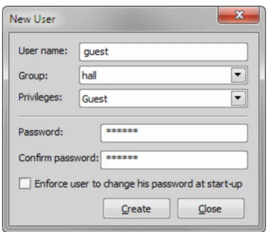
NewEnables to create newNIS-Elements ARuser account. You have to posses the privilege Modify User Rights.
Enter a new user name, assign him to one of the existing Groups and group of Privileges and set the password. Check theEnforce user to change his password at start-upoption to make the user change his password at his first login into theNIS-Elements AR.
User name and password properties
Length of the user name and password is limited to 50 characters. You can use any combination of characters, symbols or numbers (except the Windows ones: :, *, ?, ", \, /, <, >, |).
RemoveRemoves selected user account. You can select multiple accounts and delete them at once.
Copy ToChoose a user from the pull down menu whose group and group of privileges will be changed according to settings of a selected user.
DuplicateYou can easily create a new user by duplicating the existing. This preserves all account settings under a different name. If you have selected to duplicate more then one user, enter a name prefix, which is added in front of the original name for all selected duplicated accounts. User which was created as a duplicate has an empty password and is forced to change his password at next application startup.
User Accounts ListThis table displays all existing user accounts. You can sort them according to any of four columns. The first column displays type of the account. The second one shows user names. The third one displays assigned group of users. The fourth one displays assigned group of privileges. Select one or more users whose settings needs modification.
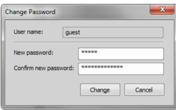
Set passwordTo change password of a selectedNIS-Elements ARuser account, press theSet password
button. You have to posses the Privilege Modify User Rights. Otherwise you can change only password of the current user. Following window appears:
Figure 2.12. Reset of password
Name of the user is displayed. Enter and confirm new password. When done, press theChangebutton.
Enforce user to change his password at start-upCheck this option to make the user change his password at his first login into theNIS-Elements AR.
Enumerate All Windows UsersThis button starts copying MS Windows accounts toNIS-Elements AR. The accounts are assigned to user groups (admin, common, guest) according to their Windows permission settings.
2.3.6. Groups Tab Options
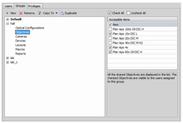
Figure 2.13. Groups tab
NewEnables to create new group of users. You have to posses the privilege Modify User Rights. Enter a name of new group.
RemoveRemoves selected groups. You can select multiple groups and delete them at once.
Copy ToChoose a group from the pull down menu which settings will be changed according to selected group.
DuplicateYou can easily create a new group of users by duplicating the existing. This preserves all group settings under a different name.
List of GroupsAll defined groups are listed in this window. Each group contains subsets. If you click on a subset, its items appear in theAccessible itemslist.
Accessible itemsThis list shows items of a selected subset. Every item has its own check box. If the check box is checked, all users assigned to the corresponding group will see the item. Otherwise they will not see the item.
Optical ConfigurationDisplays all shared optical configurations.
CamerasDisplays all installed cameras. From the pull down menu below select a camera which is used as default for users without the privilege Select Camera.
DevicesDisplays all installed devices.
LayoutsDisplays all shared layouts.
MacrosDisplays all shared macro commands. Check a macro to make the content of it visible to this Group.
ReportsDisplays all shared reports and report templates.
2.3.7. Privileges Tab Options
Figure 2.14. Privileges tab
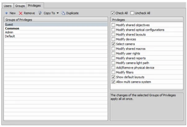
NewEnables to create new group of privileges. You have to posses the privilege Modify User Rights. Enter a name of new group.
RemoveRemoves selected groups. You can select multiple groups and delete them at once.
Copy ToChoose a group from the pull down menu which settings will be changed according to selected group.
DuplicateYou can easily create a new group of privileges by duplicating the existing. This preserves all group settings under a different name. If you have selected to duplicate more then one group of privileges, enter a name prefix, which is added in front of the original name for all selected duplicated accounts.
Groups of PrivilegesA list of all groups of privileges is displayed.
PrivilegesA list of privileges is displayed. Every item has its own check box. If the check box is checked, it grants all users assigned to the corresponding group relevant privilege to access, change, modify, etc.
Note
Users that do not have the privilege “Modify Shared Optical Configuration” can temporarily change the brightness settings (e.g. exposure time, gain, etc.) in a shared optical configuration and use such adjusted optical configuration for example in Multichannel acquisition. But all such modific-ations will not be stored and they will disappear when the application is restarted.
2.4. NIS-Elements Preferences
2.4.1. Adjusting Program Preferences
1) Run the Edit > General Options command. TheOptionsdialog window appears.
2) Select a tab which contains requested options. Options are sorted into several groups:
GeneralOptions concerning basic image operations. See 2.4.2. General.
AppearanceOptions concerning the graphical user interface. See 3.9. Appearance Options.
Open NextOptions concerning the File > Open/Save Next > Open Next menu command. See 6.1.1.3. Options for the Open Next Command.
Save NextSee 6.1.2.4. Save Next Options for more information.
MacroConfigures key shortcuts to macros and sets macros to run automatically on startup See 10.5. Macro Preferences.
MeasurementSee 8.1.4. Measurement Options for more information.
Data exportSee Data Export Options for more information.
User rightsSee 2.3. User Rights for more information.
Layout ManagerSee 3.5. Layout Manager for more information.
3) Make any changes you need in preferences and use the following buttons to manage them:
OKConfirms and saves changes made to the preferences. The dialog window is closed afterwards.
CancelCancels all changes made to the preferences. The dialog window is closed afterwards.
ApplyApplies changes made in preferences but keeps theOptionsdialog window open. You can apply changes individually on each tab.
HelpDisplays relevant help page.
2.4.2. General
Documents and History
(requires: Local Option)
Use fix path for imagesThe defined directory is always used when using the File > Open or
File > Save As command.
Limit number of opened documentsWhen this options is checked, the user is limited to a single opened image at one time.
Capture always creates a new documentIf checked, every acquisition creates a new image.
Use last LUTs on image openWhen a new image is opened, this option turns the look up tables automatically on, and copies the settings from the current or the last opened image. Some image formats (jp2, ND2) can contain the LUTs settings. If such image is opened, the saved LUTs are loaded instead of the most recently used.
Use AutoLUTs on image open for images without LUTs informationThis option keeps the AutoLUTs feature of the File > Open window always ON, and it applies AutoLUTs to the image after opening. This option isignoredif LUTs settings are saved in the image, or if theUse last LUTs on image openoption is applied.
Show mapping dialog in organizer after drag and dropDisplays theMappingwindow every time an image is inserted to a database table. It enables you to check/modify mapping of the image info values to the database table fields.
Enable saving ND experiment to TIFF seriesDisplays theSave As TIFF Seriesoption within the
ND Acquisitioncontrol panel. It enables you to save single frames of the ND experiment as tiff im-ages. You can modify the order of the dimensions and the images format (mono, color, merged). Also you choose to convert multichannel images to RGB, or to convert images to 16 bit.
Open new ND views to new windowDisplays each newly generated ND view in a separate window.
Show image info window on saveDisplays the File > Image Properties window every time an image is saved via theSave Ascommand.
Detect sequence on image openWhen you select to open an image that is a part of image sequence such as 001.jp2, 002.jp2..., it is recognized automatically and you are offered to convert it to an ND2 file.
Use zero based time scale for ND documentsSelect this option to ensure that the first frame of a time sequence will always start at 0.0s.
State of saturation indicator after startSelect what to do with the saturation indicator settings ( ) afterNIS-Elements ARis restarted. Turn it ON, OFF, or remember the last setting.
Rotation Flips and Shifts
Apply to overlaid binary layerIf checked, in overlay mode both binary and color images are rotated, shifted and flipped.
Optical Configuration
Save all camera settings to optical configuration automaticallyIf the currently selected optical configuration contains Camera Settings and this option is checked, any change of the settings is written to the optical configuration immediately.
Save brightness to optical configuration automaticallyIf the currently selected optical configur-ation contains Camera Settings, the Brightness setting is being updated continuously according to the current state. Also functionality of saving confocal brightness setting(laser power, detector gain and scan frame rate) is contained in this option.
Select corresponding optical configuration when filter changed... (requires: Local Option)Enabled if “Unselect” in the option below is chosen. AllowsNIS-Elementsto automatically change the optical configuration based on the filter selected on the microscope.
When Optical Configuration setting changed
Keep SelectedThe Opt. configuration name is marked by the “*” sign and the change is offered to be saved.
UnselectEvery change of Optical configuration setting results in its deselecting and switching to user settings.
Save all changesAll changes regarding the Opt. configuration settings are updated automat-ically according to the current state.
Temp NIS-Elements ARuses the Temp directory for storing temporary data when there is not enough RAM available. You can redirect the system to use a directory on another harddisk, which may speed up the whole system.
Defaults for this PageRestores the default setting for General Options.
2.5. NIS-Elements ER Package
Requires new HASP licenseEnhanced Resolution.NIS-ElementsER package consists ofNIS-ElementsC Package and Deconvolution package (2D, 3D and automatic deconvolution).
2.5.1. Automatic Deconvolution
Automatic deconvolution button displayed in the image toolbar can be used to easily and quickly decon-volve the currently opened image. By default, each time you execute automatic deconvolution, the de-convolution dialog window is shown. This behaviour can be enabled/disabled in the drop-down menu next to the icon of the function (Show deconvolution GUI).
1) Open the image file to be processed.
2) Click Automatic Deconvolutionon the top of the image toolbar to perform automatic
decon-volution on the current image.
Note
If the source image does not contain any deconvolution metadata, the deconvolution dialog window is opened enabling to specify the metadata and run the deconvolution process.
3. User Interface
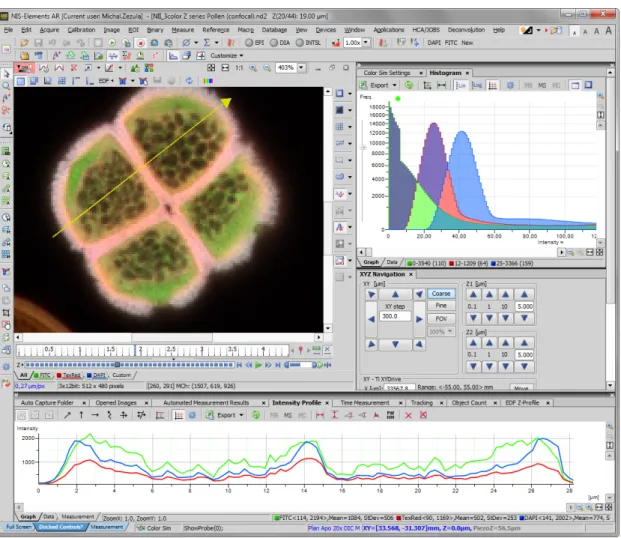
Figure 3.1. The NIS-Elements Main Window
3.1. Main Window Components
3.1.1. Main Menu
All basicNIS-Elementsfunctions are accessible from the main menu at the top of the screen. Menu commands are grouped according to their purpose.
3.1.2. Toolbars
There is a default set of toolbars, each toolbar containing number of buttons. There is also one fully customizable toolbar - the main left toolbar - to which any button can be added. Every button or whole toolbar can be hidden by user. Please see 3.3. Arranging User Interface for further details.
3.1.3. Status Bar
The status bar at the bottom of the screen displays the following information:
Figure 3.2. The application status bar
1. This part of the status bar displays available layouts.
Note
The layout Tabs may be hidden when the Show Layout Tabs option in the 3.3. Arranging User Interface window is deselected.
2. This status bar section displays the type of the currently selected camera.
3. Here you can get information about the most recently performed command. The FPS / Exposure / Focus info is shown in case of live image. The black bar indicates the focus rate. Longer black bar represents more of the image in focus.
4. This section show the name of the current objective.
5. Current coordinates of XY (Z) stage are shown in this part of the status bar.
3.1.4. Docking Panes
Docking panes are square spaces inside the application window, where you can place (dock) any of the control panels. There is one docking pane available at the Right, Bottom, and Left side of the application screen.
To Display a Docking Pane
Note
The Docking Panes sub-menu can be also displayed by right-clicking into the empty application screen.
2. The docking pane appears, either empty or with some window(s) docked inside. 3. Repeat this procedure to display more docking panes.
Handling Control Panels
Various control panels can be displayed docked within the docking panes or they can be floating. See the following picture:
Figure 3.4. The Docked Control Panel Caption
To handle the control panels (CPs), you can:
Open recently closed CPLocate the button on the main left toolbar. When you click it, the list of re-cently closed CPs appears. Pick one to display it again.
Add CP to a docking paneRight click inside a docking pane (3) to display the context menu. Select the control panel to be displayed. If the window is already opened somewhere else (in another docking pane or floating), it closes and moves to the new destination.
Close CPClick thecrossbutton (2) in the right top corner of the tab.
Drag CPDrag any CP by the tab and drop it somewhere. If you drop it by the edge of a docking pane, it will create another column of this pane. If you drop it over the caption of another CP, it will be docked in the same pane as a new tab. If dropped somewhere else, the CP will be floating.
A color frame appears when you place the mouse cursor dragging a CP over the edge of a docking pane or a caption of another CP. It indicates that if you drop it, its placement will be handled automatically.
Minimize the docking paneClick the arrows in the top left corner. The pane minimizes to a stripe by the edge of the screen. It can be restored to its original position by double clicking this stripe or by clicking the arrows again.
Close the docking paneClick thecrossbutton (4) in the docking pane caption. Or you can right click the pane and unselect theDocking Viewoption.
Display CPAnother way to display a CP is to go to theViewmenu and select the desired control panel. After that, the CP appears on the screen - floating or docked. Positions of the windows are being saved by the system so that each control panel appears in the same position as it was before it being hidden. The controls are sorted to several groups.
Shrink/Expand dockersHaving more docking panes opened, a situation where there is not enough room for the control panels can occur. In such case, theShrinkandExpandcommands shall be used.
1. Right click the pane you would like to shrink/expand. A context menu appears.
2. Select theExpand/Shrinkcommand. When one of the panes shrinks, the neighbouring pane expands to the emptied corner and vice-versa.
3.2. Image Window
Tools affecting the appearance of the current image are gathered within the image window toolbars (the top image toolbar and the right image toolbar) . There are the following buttons by default:
Figure 3.7. Image Window
Enable LUTs Applies LUTs to the image. See 6.5. LUTs - Non-destructive Image Enhancement.
Keep Auto Scale LUTsApplies the AutoScale command to the image continuously.
Auto Scale Performs automatic setting of LUTs.
Reset LUTs Discards the LUTs settings.
Show LUTs windowOpens the window with LUTs.
Pixel Saturation Indication Turns on / off pixel saturation indication without setting on / off LUTs. Select the highlighting color from the nearby pull-down menu forOversaturatedand/orUndersaturated
pixels. See 6.2.3. Channel Coloring.
Open AttachmentOpens a file previously attached and saved with the ND2 file. To attach any file to an image, right-click inside the image, selectAdd Attachmentand choose a file to be attached. Maximum size of the attached file is 64 MB. Context menu over the image also enables toOpen Attach-ment...(same functionality as the button),Save Attachment As...(saves the attached file separately) orRemove Attachment(attachment is removed from the ND2 file).
Split ComponentsTurns ON a special view, where color channels of the image are displayed separately (tiled). This mode is also supported in 6.3.3. Volume Viewer.
Fit to screen Adjusts zoom to view the whole image within theNIS-Elements ARscreen.
Best FitAdjusts zoom to fit the image window in one direction and fill the available area with the image.
1:1 ZoomAdjust zoom so that one pixel of the image matches one pixel of monitor.
Zoom In Increases magnification of the image.
Zoom OutDecreases magnification of the image.
Show ProbeThis button activates the probe. The probe affects histograms, auto exposure and auto white balance functions.
Show Background ProbeActivates the background probe. Some commands use the BG probe data as reference.
Show GridDisplays the grid for rough measurements.
Show Scale Displays the image scale.
Show FrameDisplays and applies the measurement frame.
Turn ROI On/OffDisplays the Measurement Region Of Interest.
Show ProfileDisplays the Measure > Intensity Profile control panel. It allows you to specify a linear section in the image of which the pixel intensities graph will be created.
View LUT IntensityDisplays the scale of intensities used inside the image. It works on monochro-matic images or a single image channel.
Show AnnotationsDisplays the vector layer which typically consists of annotation objects (text labels, arrows) and measurement objects.
View Binary Displays the binary layer of the image.
View ColorDisplays the color layer of the image.
View OverlayDisplays the color layer and the binary layer in overlay.
Tip
Channel Tabs
Figure 3.8. Channel tabs of an RGB image
Channel tabs at the bottom left corner of the image window enable switching between image channels. You can also edit their properties using commands available via a context-menu. See also 6.2. Image Layers.
Status Bar
The status bar at the bottom of the image window displays the following information:
Figure 3.9. Status bar of the image window
1. The first field of the image window status bar Image displays the calibration. See also 8.1.1. Calibration , 8.1.1.3. Units.
2. Image bit depth (8bit, 12bit, 16bit, etc.) followed by Image size. You can change the displayed units from the context menu.
3. Pixel coordinates of the mouse cursor along with channel intensities, Binary layer value (0 or 1) and the Color mode (RGB, Monochromatic, etc.).
3.3. Arranging User Interface
Having a well organized application layout can help you make the work withNIS-Elements ARvery ef-fective. There are the following options on customizing the appearance ofNIS-Elements AR:
Custom window placementAll control panels (Camera Settings, Measurement, Histogram, LUTs, etc.) can be arranged inside or outside of the main application window.
Compact window or multiple windowsThe control panels as well as toolbars can be floating or docked on sides of the application screen.
Multiple monitor supportTheNIS-Elements ARwindow can be stretched to occupy two monitors. When you switch from different application,NIS-Elements ARwill be activated on both monitors.
Customized toolbarsToolbar buttons may be added and removed from toolbars. See 3.6. Modifying Toolbars.
• The channel tabs and the layout tabs may be hidden to save some screen-space. Display the 3.9. Appearance Options window and de-select theShow Channel Tabsand theShow Layout Tabsoptions.
• Image controls and the image status bar may be hidden. Use theAuto hide bottom toolbaroption of the 3.9. Appearance Options window.
• When an image is displayed in great magnification, scroll bars automatically appear by the sides of the image window. You can hide them by de-selecting theShow Scrollbarscontext menu option.
3.4. Layouts
A layout in the context ofNIS-Elements ARis a set of options describing the arrangement of control panels, toolbars, and menu items. Blue tabs representing active layouts appear in the application status bar. The following layouts are placed there by default:
•Full Screen
•Docked Controls
•Measurement
Other layouts can be added and managed via the Layout Manager. To hide/show the layout tabs within the status bar, go for View > Layout Manager and (de)select theShow Layout Tabsoption.
To Create a New Layout
Figure 3.10. Layout tabs
1. Modify the current layout so that it suits your concept of work.
2. An asterisk*appears next to the layout name (to indicate it has been modified).
3. Right click the layout tab and select theSave Current Layout AsorSave As Defaultcommand. If you do not need to create a new layout but would like to save the changes made, just right click the current (asterisk-marked) tab and select theSavecommand from the menu.
4. Write the new layout name and confirm it by OK .
5. A new tab appears and the layout is saved to the list of layouts.
To Reload Previous Layout Settings
You may want to undo the changes made to the layout. Mostly, it can be done by theReloadcommand. Or by selecting theLoad Defaultcommand.
• Right click the asterisk-marked (recently modified but not saved) tab and choose theReloadcommand. The application restores the last saved state of the layout.
• Right click the asterisk-marked tab and choose theLoad Defaultcommand. The application loads the previously saved default layout.
3.5. Layout Manager
Run View > Layout Manager to display the Layout Manager. The list of currently available layouts is placed on the left side of the layout manager. Each layout may contain information about controls, toolbars, menu, and commands to be performed when switching between layouts.
Figure 3.11. List of Layouts
Modifying the Layout Settings
1. Select items within theGlobal Layoutlist which you want to be shared by all layouts.
2. The check marks on the left of the layout names indicate the layout visibility. Select the ones you want to display in the application status bar.
3. If an item within some particular layout is not selected, it means you do not want to customize it and the global settings - if selected within theGlobal Layout- will be used. If the item is not selected within the Global Layout either, the settings of the most recently active layout will be used. 4. Set whether the layout isPrivateorShared. If setPrivate, it will not be visible for other users. See
2.3. User Rights.
5. Customize each item according to your needs (see below).
Layout Manager Tools
NewAdds a new layout to the list of layouts.
ActivateMakes the selected layout active.
Load DefaultLoads original settings of the selected pre-defined layout (Full Screen,Docked Controls,
Measurement) so that it looks just like after the program installation.
Lock LayoutSelect a layout component and click this button to lock these elements so that they cannot be moved or closed. To unlock these components, click the button again or right-click the locked layout tab at the bottom and clickUnlock Layout.
Apply to All Ensures that the executed changes will be applied to all layouts.
ImportEnables to load a previously saved set of layouts from an XML file. When you try to import a layout with already existing name, you will be prompted to choose whether: the imported layout replaces the existing colliding layout, or is not imported, or is imported and renamed.
Export LayoutsThe settings of layouts can be saved to an external XML file. Use thisExportbutton. In the windows that appears, define the destination file name and check which layouts will be included in the exported xml file.
3.6. Modifying Toolbars
Hiding Toolbar Buttons
1. Display Layout Manager by the View > Layout Manager command.
2. Select theToolbarsitem within the list of layouts. The right-side part of the window changes.
3. Choose one of the toolbars which you would like to modify from theToolbarpull-down menu.
4. If selected, de-select theUse Defaultoption on the right.
5. Any button of the toolbar may be hidden by de-selecting it. No buttons can be added to any of the toolbars except theMain Left Toolbar.
6. The whole toolbar can be hidden by de-selecting theShow Toolbarcheck box.
7. There are two sizes of buttons available. Select theLarge Buttonsoption to use the larger one. This setting is shared by all toolbars.
Adding Buttons to the Left Toolbar
Custom user buttons can be added to the main left toolbar. You can define your own buttons which run single macro functions or execute macros . Select theMain Left Toolbarfrom the pull-down menu.
Let's say that we very often use the Image > Contrastcommand. It is useful to add a shortcut button to the toolbar.
1. Press theAddbutton, and chooseCommandfrom the pull-down menu:
2. A new command -Command0- is added to the list.
3. Now, assign a macro command: Open the pull-down menu on the right side of theCommandedit box and clickCommand List.
4. A list of commands appears. Choose_Contrast().
5. Confirm the selection byOK.
Note
It is possible to assign a sequence of commands to a single button by repeating this procedure.
If you are not satisfied with the default icon, you can change it by pressing the Change... button. A window for selecting the icon appears. You can select the image from theNIS-Elements ARicon set or load some other from any file containing icons (ico, dll). You can define another icon for the command in a disabled state, too.
It is handy to define a tool-tip (a text that appears when the mouse cursor is placed over the icon) for your command. Simply write the text into theTooltipbox. You can change the position of the command in the toolbar using the arrow buttons. The Default button discards your changes and inserts the default set of commands to the toolbar.
3.7. Modifying Menus
TheMain Menuand some of theContext Menuswithin the application window may be modified. Items of the context menus can be hidden by de-selecting them similarly to the toolbars. The main menu can be modified as follows:
Modifying the Main Menu
1. Display Layout Manager by the View > Layout Manager command.
2. Select theMain Menuin the topmost pull-down menu.
3. Any item may be added to the main menu - aSeparator, aMenu Command, a sub-menu (Menu Popup), and even a new menu (Main Menu Popup) - by theAddbutton.
4. Select the existing menu item under which you would like to place the new item. 5. Click theAddbutton and select the item to be added from the pull-down menu.
TextThis is the text which appears in the pulldown menu. You may add “&” before any letter -such letter will be considered a keyboard shortcut when browsing the menu.
Hot keyOne or more hot key shortcuts may be assigned to the command. Just press theAdd
button and press the key combination. PressRemoveto remove the selected hot key.
Enabled/Disabled bitmap, CommandThese fields serve for assigning a bitmap image and a macro function to the menu command. It works the same way as when modifying the Main Left Toolbar (described above).
Note
The Default button discards all changes and loads the main menu original configuration. The Remove button deletes the selected item. The arrow buttons move the selected item up/down. The Use Default check box, when selected, applies the default settings to the menu.
3.8. Running a Macro Upon Layout Change
A macro command or a macro can be run upon layout change.1. Display the layout manager by the View > Layout Manager command.
2. Select the layout by displaying of which the macro function will run and select theCommandscheck box.
3. The following box appears on the right side:
4. Select the timing. The “before” option will run the command when you click on the layout tab, but before actually changing the layout. The “after” option runs the command right after the layout is changed.
5. When the field is enabled, type the command or insert it via the pull-down menu.
3.9. Appearance Options
General appearance adjustments can be made in theOptionswindow. Run the Edit > General Options
command and switch to theAppearancetab.
Color schemeThere are the following color schemes predefined within the application: Light scheme, Dark scheme, Black scheme.
LanguageSelect the language to be used in GUI. The language pack is a part of the Local Option feature set.
Prompts on Image Save dialogActual words used on buttons of the window which appears if an image has been modified and is about to be closed.
The Z value displayed in statusbarHaving two Z devices, select whether to display Z1, Z2 or both on the main status bar.
Close ND Acquisition window after RunThe View > Acquisition Controls > Capture Timelapse window will be closed automatically upon acquisition start.
Enable Z intensity controlThis option enables the View > Acquisition Controls > Z Intensity Correction
withinNIS-Elementsuser interface.
Image window toolbarsYou can decide whether the top and side image toolbar is integrated into the main toolbar (Common for all Images) or whether each image has its own set of toolbars (Visible for each image). The most space-saving option is to use shared toolbars and hide the image status bar and the ND2 control bar (6.3.1.1. Control Bar) automatically (Common for all images, auto hide bottom toolbar). It will show up only when the mouse cursor rolls over the bottom part of the image.
In theRight Toolbarsection you can select the appearance of buttons having more sub-options. See 3.2. Image Window.
Auto hide bottom toolbarThis option hides the image status bar and the ND2 control bar (6.3.1.1. Control Bar) automatically. It is displayed only when the mouse cursor rolls over the bottom part of the image picture.
Show channel tabsShow channel names and colors in the image window status bar.
Show Layout tabsShow layout tabs in the main status bar.
Show Task BarIf unselected, the Windows taskbar will be hidden.
Default vertical docker on the (requires: Local Option)
Select the preferred side for the default vertical docking pane.
Keep text size while zoomingWhen selected, text annotations will not be zoomed with the image. See
View > Analysis Controls > Annotations and Measurements.
Allow zoom factors lower than best fitWhen selected, the image can be resized to be smaller than displayed using the View > Zoom > Fit to Screen command.
Lock camera magnificationIf you are used to switch between two camera modes (resolutions), this option ensures that the scene observed does not change its size or position.
Keep picture window aspectIf checked, the image window respects the image size while zooming.
Initial ZoomYou can select the zoom factor of the newly opened images. The options are Best Fit, 200, 100, 50, 25%.
Initial zoom 100% for Live and CaptureWhenever a new Live or Captured window is opened, the zoom will be automatically set to 100%.
Default Volume View Rendering EngineSwitch between the Old/New engine used in the Volume Viewer.
4. Cameras & Devices
4.1. Basic Workflows
4.1.1. Camera Selection on Startup
Let's assume the camera works properly, is connected to the PC with proper system drivers installed and running (if required by the camera).
Setting Up the Camera
1)
Select Camera Driver
You will be asked to select the camera driver every time you launchNIS-Elements AR. You can change the driver later using the Acquire > Select Driver command. Choose the driver that matches your camera:
Multiple Cameras
Two cameras can be connected to one system. If this is your case and you intend to use both cameras, check theEnable Multi Cameraoption and select theSecond driverfrom the list.
The following set of buttons appears in the top toolbar when multiple cameras are used:
2)
Selecting a Camera
Color cameras can be used in a monochromatic mode. The actual camera type (color/mono) can be selected by the Acquire > Select *camera name* command.
Note
The emulated monochromatic mode is optimized for use with fluorescence specimen where often only a single-color signal is being captured. The following formula is used to compute intensity of the emulated mono image:
I = (Ir * Wr) + (Ig * Wg) + (Ib *Wb)
Where: W is channel weight calculated from the channel histogram and I is channel intensity. W ensures, that channels containing some signal are accentuated while channels without signal are suppressed. As a result, depending on conditions, the brightness of a monochrome image might not change even if the lamp light intensity is changed.
3)
Adjust the Camera Settings
Exposure time, camera resolution, and other camera-specific features are adjustable from the
Camera Settingswindow. To invoke it, use the Acquire > Camera Settings command.
4.1.2. Optical Configurations
4.1.2.1. Introduction to Optical Configurations
Typically, a laboratory computer image analysis system consists of a computer, a camera, and a micro-scope equipped with certain accessories (objectives, filters, shutters, illumination, rotary changers, etc). Most of the mentioned microscopic hardware can be motorized and therefore can be controlled via NIS-Elements AR. In addition, it is possible to integrate single settings of all these devices into one compact set calledOptical Configuration. It is recommended to create several optical configurations containing particular devices settings. Then a single click can completely change the current hardware configuration.
4.1.2.2. Creating New Optical Configuration
1) Please check that all the devices (microscopes, cameras, etc.) which you want to associate with the new optical configuration are properly attached to the system and working.
2) Choose the Calibration > New Optical Configuration command. In the window which appears,
adjust the settings of the devices to match the intended state which will be saved to the optical configuration.
3) Type the name of the new optical configuration to theNamefield. Use a short descriptive name, the name is used on the button in the main toolbar when you select theShow on toolbaroption.
4) In the left column, select which device settings to associate with the Optical configuration.
Camera settingA list of the current camera properties appears on the right. It is being updated dynamically.
If you want to use stored ROIs for Camera ROI setting (turn ROI on/off and use the stored ROI value), tick “Use Stored ROI” checkbox in the Camera features box.
Channel setupThese settings determine how channels of newly captured images will be named and what color will be assigned to them. The available properties depends on the current camera setup (color/mono, triggered acquisition engaged or not, dual view engaged or not, etc.). In the mono camera mode, you can either assign the name, the emission length and color to the channelManually, or leave this task toNIS-Elements AR(theAutomaticallyoption). In such case, information of the light path (emission wavelength) will be used to determine the channel name and color.
Microscope settingIf there is more than one shutter available and you would like to associate a shutter with the optical configuration, select which one is theActive Shutterfrom the pull-down menu. Select which parts of the microscope shall be included in the configuration by checking them in theUsed devicesdialog box.
Note
Active shutters remember their aperture setting and display it in the Microscope setting section.
ObjectiveAn objective mounted to a motorized nosepiece can be included in the configuration. Select the objective from the pull-down menu. Objectives which are currently assigned to any position of the nosepiece are listed. See 4.1.3. Objectives.
Note
The objective must be assigned to a nosepiece position via the microscope control pad or the nosepiece control panel beforehand.
5) If some of the device settings still need to be adjusted, click the Camera & Devices Controls button and select the appropriate control panel from the pull-down menu. Adjust the settings within the control panel, the optical configuration will be updated automatically.
6) ClickFinishto save the new optical configuration and to close the window.
7) You can create more optical configurations by repeating the procedure. The optical configurations are saved to registry immediately. A backup of optical configurations can be made by running the Calibration > Optical Configurations command and clicking theExportbutton.
4.1.2.3. Managing Optical Configurations
To display the optical configurations manager window, run the Calibration > Optical Configurations
command. You can make the following actions from the window:
• Create, duplicate, rename, delete, copy settings and switch between optical configurations. • Modify optical configuration properties.
• Import and export optical configurations to/from an XML file.
4.1.2.4. Operations with Optical Configurations
Once created, the configuration appears in the list and can be shared with other users by changing the
Privateoption toShared(see 2.3. User Rights). The following operations can be performed on the selected configuration:
• It can be deleted by pressing theRemovebutton. A confirmation dialog box appears.
• Its name can be changed by theRenamebutton. A button with the configuration name appears in the toolbar (if theShow on toolbaroption is selected).
• The configuration settings may be transferred to another optical configuration by the Copy to button. Press the button and select the optical configuration to be overwritten with the current one.
• A copy of the configuration can be made via theDuplicatebutton.
• The configuration can be applied to by theSet As Activebutton.
• The settings of all optical configurations can be exported to an external XML file using theExport
button.
• The previously exported optical configurations settings can be loaded from the XML file via theImport
button.
• The list of optical configurations can be ordered manually using the arrow-up and arrow-down buttons. • Each configuration can be arbitrarily modified within the right-side portion of the window.