6
Controlling Access
Through the Firewall
A firewall’s main function is to provide effective security between pairs of its interfaces. To do this, all of the traffic destined to pass through it must undergo a variety of operations, inspections, translations, filters, and special handling. You must configure each aspect of these actions in order to thoroughly enforce the security policies that apply to your network.
All of the features related to controlling user access through the firewall have been collected in this chapter. The size of the chapter is a testament to the broad range of security policy tools available to you, as a firewall administrator.
6-1: Routed and Transparent Firewall Modes
Traditionally, Cisco firewalls have operated by performing Layer 3 (IP address) operations. Naturally, the stateful inspection process can look at higher layers within the IP packets being examined. But the firewall itself has maintained its own interface IP addresses and acted as a router or gateway to the networks that connect to it. As well, all of the traffic inspection and forwarding decisions are based on Layer 3 (IP address) parameters. This is known as the routed firewall mode. Each firewall interface must be connected to a different IP subnet, and be assigned an IP address on that subnet. When a routed firewall is installed or inserted into a network for the first time, the network must become segmented across the firewall’s interfaces. For example, where a single IP subnet used to be, the inside and outside interfaces now form the boundary of two separate subnets. This can make the installation difficult, as some readdressing must take place. The easiest approach is to keep the original IP addressing on the firewall’s inside interface, where the majority of protected hosts reside. The outside interface can take on an address from a new subnet that is shared between the firewall and the next-hop router. In other words, the outside of the firewall usually has a lesser number of directly connected hosts to readdress to a new subnet.
Routed firewalls can also participate in IP routing by using a dynamic routing protocol such as RIP or OSPF. The firewall can coexist with other routers in the network and maintain a dynamic routing table.
By default, the Adaptive Security Appliance (ASA) and Firewall Services Module (FWSM) platforms are configured for routed mode. You can configure IP addresses on the firewall interfaces, IP routing, and other Layer 3 features by following the guidelines found in Chapter 3, “Building Connectivity.”
TIP You can see the current firewall mode by using the following command:
Firewall# show firewall
The result is either “Firewall mode: Router” or “Firewall mode: Transparent”. If you need to configure a firewall back to routed mode, use the following command:
Firewall(config)# firewall router
A Cisco firewall can also be configured to operate in transparent firewall mode. The firewall appears to operate as a Layer 2 device, without becoming a router hop or a gateway to the connected networks. This is also known as a Layer 2 firewall or a stealth firewall, because its interfaces have no IP addresses and cannot be detected or manipulated. Only a single management address can be configured on the firewall.
As a Layer 2 device, a transparent mode firewall can be dropped or wedged into an existing network, separating the inside and outside without changing any existing IP addresses. This is commonly calledbump-in-the-wire because the firewall does not break or segment the IP subnet along a wire— it more or less becomes part of the wire. This makes a new installation very straightforward.
TIP Cisco firewalls running PIX release 6.3 or earlier operate solely in the routed firewall mode. Beginning with FWSM 2.2(1) and PIX 7.0, you can configure a firewall to operate in either the routed or transparent firewall mode, but not both.
You can think of a transparent mode firewall as a type of transparent bridge, where packets are bridged from one interface to another based only on their MAC addresses. The firewall maintains a MAC address table from received packets, containing the source MAC address and the source interface. The firewall is able to forward a packet by knowing the location or the egress interface of the destination MAC address.
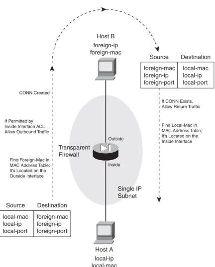
Figure 6-1 illustrates the transparent firewall process. Host A sends a packet to Host B. Notice that Hosts A and B are located on the same IP subnet. Their local-ip and foreign-ip addresses only designate that “local” is on the inside of the firewall and “foreign” is on the outside. When the firewall builds a conn table entry, the host addresses are shown in this fashion.
TIP In transparent mode, a firewall can support only two interfaces—the inside and the outside. If your firewall supports more than two interfaces from a physical and licensing standpoint, you can assign the inside and outside to two interfaces arbitrarily. As soon as those interfaces are configured, the firewall does not permit a third interface to be configured.
Some platforms also support a dedicated management interface, which can be used for all firewall management traffic. However, the management interface cannot be involved in accepting or inspecting user traffic.
In multiple context mode, each context also has two interfaces (inside and outside). However, each context must use a pair of interfaces that is different than any other context. In other words, contexts cannot share inside and outside interfaces because of the bridging operation.
Figure 6-1 Transparent Firewall Operation
Transparent Firewall Single IP Subnet Outside Host B foreign-ip foreign-mac Find Local-Mac in MAC Address Table; It’s Located on the Inside Interface If CONN Exists, Allow Return Traffic CONN Created
Find Foreign-Mac in MAC Address Table; It’s Located on the Outside Interface If Permitted by Inside Interface ACL Allow Outbound Traffic
Host A local-ip local-mac Inside foreign-mac foreign-ip foreign-port Source Destination local-mac local-ip local-port local-mac local-ip local-port Source Destination foreign-mac foreign-ip foreign-port Section 6-1
When a firewall enters transparent mode, it no longer supports or has a need for address translation. After all, that is a function based on having different IP subnets on different firewall interfaces. In transparent mode, both interfaces must share the same IP subnet. However, IP packets are still inspected without the Layer 2 limitation. Full extended access lists (IP protocol and port numbers) are used to evaluate traffic policies, and the firewall’s application inspection engines are able to interpret IP activity at any layer.
If a transparent firewall acts as a Layer 2 device, is it limited to only IP traffic? From a traffic inspection standpoint, it is; only IP traffic can be inspected and policies enforced. However, from a bridging perspective, the firewall can transparently bridge non-IP packets from one interface to another. This is done by configuring the permitted EtherTypes explicitly in a special interface access list.
A transparent firewall can also maintain an Address Resolution Protocol (ARP) table, where Media Access Control (MAC) and Internet Protocol (IP) addresses are associated as a pair. These are learned from ARP replies that are overheard on an interface. Normally, the ARP table is used only for management traffic to and from the transparent firewall, when the firewall itself needs to send packets to a destination.
You can configure the firewall to support ARP inspection, which can detect and prevent ARP spoofing. ARP requests and replies are forwarded through the firewall by default, as if the two firewall interfaces were bridged. This creates the potential for a malicious host to send spoofed ARP replies with its own MAC address. By doing so, the malicious host can advertise itself as a router’s IP address, causing other hosts to send their traffic to it instead of the router.
ARP inspection uses static ARP entries as the basis for its inspection process. The firewall examines each ARP reply packet it overhears and compares the source IP and MAC addresses, as well as the source interface, to known static entries in its own ARP table. If the ARP reply matches an existing entry, it is allowed to pass through the firewall. If any of its information conflicts with an existing entry, the firewall assumes the ARP reply contains spoofed addresses and drops the packet. If an existing ARP entry cannot be found, the firewall can be configured to transmit or drop the ARP reply packet.
Configuring a Transparent Firewall
Use the following steps to configure a firewall for transparent mode. 1. Enter transparent firewall mode:
Firewall(config)# firewall transparent
By default, a firewall operates in the routed mode. You can use this command to initiate the transparent firewall mode. Transparent mode begins immediately and does not require a firewall reload.
Because transparent and routed modes use different approaches to network security, the running configuration is cleared as soon as transparent mode begins. The idea is to enter transparent mode and build an appropriate configuration from scratch.
For that reason, you should save the routed mode running configuration to Flash memory or to an external server. That way, you have a copy in case you need to revert back to routed mode or you need to refer to some portion of that configuration.
You can always display the current firewall mode with the show firewall command. As an example, a firewall is configured for transparent mode in the following command sequence:
Firewall# show firewall
Firewall mode: Router Firewall# configure terminal
Firewall(config)# firewall transparent
Switched to transparent mode Firewall(config)# exit
Firewall#
Firewall# show firewall
Firewall mode: Transparent Firewall#
2. Configure an interface
In transparent mode, none of the firewall interfaces can support an IP address. You still have to configure the necessary interface media parameters (speed and duplex), any virtual LAN (VLAN) information, a logical name, and a security level. These parameters are configured in the following steps:
a. Define a physical interface.
The interface is referenced by its hardware-id, such as GigabitEthernet0 or Ethernet0. (The actual name is not case sensitive when you enter it.)
You can set the interface speed with one of the auto(negotiate the speed; the default), 10 (10 Mbps only), 100(100 Mbps only), or nonegotiate(fiber optic interfaces only) key-words. The duplex mode can be set using one of the following keywords: auto (auto-negotiate; the default), full (full-duplex only), or half(half-duplex only).
By default, interfaces are administratively shut down with the shutdown command. You can enable an interface by using the no shutdown interface configuration command.
b. Define a VLAN interface.
FWSM N/A
ASA Firewall(config)# interface hardware-id
Firewall(config-if)# speed {auto | 10 | 100 | nonegotiate} Firewall(config-if)# duplex {auto | full | half}
Firewall(config-if)# [no] shutdown
FWSM Firewall(config)# interface vlan vlan_id
ASA Firewall(config)# interface hardware_id[.subinterface]
Firewall(config-subif)# vlan vlan_id
On a FWSM platform, VLAN interfaces are inherent, as it has no physical interfaces at all. Only the VLAN number vlan_id needs to be provided.
On an ASA, logical VLAN interfaces must be carried over a physical trunk interface, iden-tified as hardware-id (GigabitEthernet0, for example). A subinterfacenumber is added to the physical interface name to create the logical interface. This is an arbitrary number that must be unique for each logical interface. The VLAN number is specified as vlan-idin a separatevlansubinterface configuration command.
Packets being sent out a logical VLAN interface are tagged with the VLAN number as they enter the physical trunk link. The VLAN number tag is stripped off at the far end of the trunk, and the packets are placed onto the corresponding VLAN. The same process occurs when packets are sent toward the firewall on a VLAN.
The trunk encapsulation used is always IEEE 802.1Q, and the tagging encapsulation and unencapsulation are automatically handled at each end of the trunk. Make sure the far end switch is configured to trunk unconditionally.
c. Name the interface and assign a security level.
On a FWSM platform, the interface is identified by its vlan-id(vlan5 for example; the
wordvlan is always present). If multiple security context mode is being used, the vlan-id
could be an arbitrary name that has been mapped to the context by the allocate-interface command in the system execution space.
The interface is given the arbitrary name if_name(1 to 48 characters) that other firewall commands can use to refer to it. For example, you could name an interface as “inside”, “outside”, or something completely different.
A security level is also assigned to the interface as a level (a number 0 to 100, from lowest to highest). On a FWSM, the level must be given immediately following the security key-word, as in securitylevel. Security levels 0 and 100 are reserved for the “outside” and “inside” interfaces, respectively. Other perimeter interfaces should have levels between 1 and 99.
As an example, the outside interface could be configured as follows:
FWSM Firewall(config)# nameif vlan-id if_name securitylevel
ASA Firewall(config-if)# nameif if_name
Firewall(config-if)# security-level level
FWSM Firewall(config)# nameif vlan10 outside security0 ASA Firewall(config)# interface gigabitethernet0
Firewall(config-if)# nameif outside
TIP Security levels are only used to determine how the firewall inspects and handles traffic. For example, traffic passing from a higher security interface toward a lower one is assumed to be going toward a less secure area. Therefore, it is forwarded with less stringent policies and traffic coming in toward a higher security area.
In addition, firewall interfaces must have different security levels, unless the same-security-traffic permit inter-interface global configuration command has been used.
3. Configure a management address:
Firewall(config)# ip address ip_address subnet_mask
The firewall can support only a single IP address for management purposes. The address is not bound to an interface, as in routed mode. Rather, it is assigned to the firewall itself, accessible from either of the bridged interfaces.
The management address is used for all types of firewall management traffic, such as Telnet, SSH, HTTP, SNMP, Syslog, TFTP, FTP, and so on.
TIP A transparent firewall can also support multiple security contexts. In that case, interface IP addresses must be configured from the respective context. The system execution space uses the admin context interfaces and IP addresses for its management traffic.
4. (Optional) Configure routing information for management purposes:
Firewall(config)# route if_name foreign_network foreign_mask gateway [metric]
You can configure a static route to allow the firewall to send management traffic to addresses that are not on the local IP subnet. Dynamic routing protocols are not supported in the transparent firewall mode.
The remote network can be found on the firewall interface named if_name(outside, for example), and has network address foreign_network and subnet mask foreign_mask. The next-hop router address is given as gateway. You can also specify a distance metric, which is the number of router hops until the gateway is reached. If you omit the metric, it defaults to one hop. You can repeat this command to define other stable, static routes.
You do not have to configure a static route for the subnet directly connected to the firewall interfaces. However, you should define one static route as a default route toward the outside public network. For that, use 0 for the foreign_network andforeign_mask values. If you have
other IP subnets active on the inside of the firewall, you need to define static routes for each of them.
As an example, a firewall is located on the network 10.1.0.0 255.255.0.0. Its next-hop router on the outside interface is 10.1.1.1. A router exists at 10.1.1.2 on the inside of the firewall, where subnets 192.168.1.0/24 and 192.168.100.0/24 can be found. The following commands can be used to configure this routing information on a transparent firewall:
Firewall(config)# route outside 0 0 10.1.1.1 1
Firewall(config)# route inside 192.168.1.0 255.255.255.0 10.1.1.2 1
Firewall(config)# route inside 192.168.100.0 255.255.255.0 10.1.1.2 1
5. (Optional) Manipulate the MAC address learning process:
By default, a firewall learns MAC addresses as they are received on any interface. You can use the following commands to display the current MAC address learning state and the current MAC address table entries, respectively:
Firewall# show mac-learn
Firewall# show mac-address-table [count] [static] [if_name]
You can specify a single interface as if_name on an ASA or as interfaceif_name on a FWSM platform.
As an example, the following output indicates that MAC address learning is enabled on both firewall interfaces, and the MAC address table has been populated with a few entries:
Firewall# show mac-learn
interface mac learn outside enabled inside enabled Firewall#
Firewall# show mac-address-table
interface mac address type Age(min)
---outside 00a0.c900.0201 dynamic 5
inside 0050.e2c6.f680 dynamic 4
outside 0008.20f7.fbfc dynamic 4
Firewall#
You can use any of the following steps to modify the MAC address learning process:
a. (Optional) Set the MAC address table aging time:
Firewall(config)# mac-address-table aging-time minutes
As new addresses are learned, they are placed in the MAC address table. If no traffic is seen to include a MAC address that is already in the table, that entry is aged out and removed after minutes (5 to 720 minutes, default 5).
b. (Optional) Define a static MAC address table entry:
Firewall(config)# mac-address-table static if_name mac_address
You might define a static entry for a MAC address that can never be learned. This might occur if a host or server always listens to traffic using one MAC address and transmits using another. In that case, the transmit address can be learned, while the receiver address cannot.
After a static entry is configured, the firewall always expects that MAC address to be found on the specified interface. If the same MAC address appears on a different firewall interface, the firewall drops those packets.
As an example, the following commands configure two static entries in the MAC address table:
Firewall(config)# mac-address-table static inside 0006.5b02.a841
Firewall(config)# mac-address-table static outside 0040.9646.6cf6
c. (Optional) Disable MAC address learning on an interface:
Firewall(config)# mac-learn if_name disable
By default, MAC address learning is enabled on every firewall interface. You can disable it on a firewall interface named if_name (outside, for example) so that only static MAC address table entries are used during a packet forwarding operation.
This might be handy in a scenario where you want to keep tight control over the MAC addresses that can be learned dynamically. However, static entries would need to be added for each new host, increasing the amount of firewall administration needed.
6. (Optional) Use ARP inspection
a. Add a static ARP entry:
Firewall(config)# arp if_name ip_address mac_address
The IP address will be associated with the MAC address (dotted triplet nnnn.nnnn.nnnn format). These are expected to be found on the firewall interface named if_name (outside, for example).
Static ARP entries never age out. To clear a static ARP entry, repeat the command by beginning with the nokeyword.
TIP Thearp command syntax also includes an optional alias keyword. In routed firewall
mode, this makes the firewall use proxy ARP when it gets an ARP request for that address, rather than forward the request on through to the actual target.
In transparent mode, this keyword has no effect. The firewall will not interact with other hosts using Layer 3 mechanisms, so proxy ARP is not possible.
As an example, the following commands configure static ARP entries in preparation for ARP inspection:
Firewall(config)# arp inside 192.168.198.199 0006.5b02.a841
Firewall(config)# arp outside 172.21.4.9 0040.9646.6cf6
b. Enable ARP inspection on an interface:
Firewall(config)# arp-inspection if_name enable [flood | no-flood]
By default, ARP inspection is disabled on all firewall interfaces. When enabled, ARP replies received on the interface named if_name (outside for example) are inspected and matched against known static ARP entries. One of the following actions is taken: — If the MAC address and the IP address are both found in the ARP table in a single
entry, the ARP reply must be valid and is allowed to pass through the firewall. — If either the MAC address or the IP address is found in the ARP table, but not both
in a single entry, the ARP reply contains invalid or spoofed information. Therefore, it is dropped and not forwarded through the firewall.
— If neither MAC nor IP address is found in the ARP table, you can select the action as one of: flood(forward or flood the ARP packet out the other firewall interface so it can reach its destination) or no-flood (drop the ARP packet without forwarding it). By default, the flood action is assumed.
TIP ARP inspection is only effective in handling ARP packets that need to traverse the firewall. In other words, the ARP requester and responder are located on different firewall interfaces. If both hosts are located on the same firewall interface, the ARP reply can be answered directly without having to pass through the firewall.
You can display the ARP inspection status on each interface with the following command:
Firewall# show arp-inspection
For example, the firewall in the following output has ARP inspection enabled on both interfaces, but only the inside interface is configured to flood unknown ARP replies:
Firewall# show arp-inspection
interface arp-inspection miss ---outside enabled no-flood inside enabled flood Firewall#
TIP If you are having trouble getting ARP inspection to work properly, make sure that all of the addresses involved in ARP requests and replies are configured as static ARP entries. If the firewall receives an ARP packet and finds a corresponding entry in its ARP table that was learned dynamically, the ARP packet is dropped. Only static ARP entries are used with ARP inspection.
For example, ARP inspection has been enabled on the outside interface of a firewall. The firewall has already learned the MAC and IP addresses for a router on the outside, and has created a dynamic ARP entry for it. When the router sends an ARP reply toward the outside firewall interface, ARP inspection rejects it. The following syslog output is generated when this happens:
%ASA-3-322002: ARP inspection check failed for arp response received from host 0008.20f7.fbfc on interface outside. This host is advertising MAC Address 0008.20f7.fbfc for IP Address 192.168.93.129, which is dynamically bound to MAC Address 0008.20f7.fbfc
Firewall# show arp
outside 192.168.93.129 0008.20f7.fbfc outside 192.168.93.130 0008.20f7.fb00 inside 192.168.93.134 0050.e2c6.f680 Firewall#
Although it looks like everything matches up with the outside host’s addresses, the problem is that the ARP entry was dynamically learned and created.
7. Configure interface access lists.
Before traffic can be forwarded through the firewall, make sure to configure the appropriate security policies by applying an access list to each interface. Access lists are covered in detail in Section 6-3, “Controlling Access with Access Lists.”
8. Configure a forwarding policy for non-IP protocols.
a. Define an access list:
By default, only IP packets are allowed to pass through a firewall (providing the packets are permitted by the various inspection processes). You can create an access list that defines a policy on whether non-IP protocols can be forwarded through the firewall. This command defines an Access Control Entry (ACE) for the access list named acl_id. You can permit or deny the EtherType that is specified. There is always an implicit deny
FWSM Firewall(config)# access-list acl_id ethertype {permit | deny} {unicast | multicast | broadcast | ethertype}
ASA Firewall(config)# access-list acl_id ethertype {permit | deny} {any
| bpdu | ipx | mpls-unicast | mpls-multicast | ethertype}
allACE at the end of every access list. Therefore, all non-IP EtherTypes are dropped unless they are explicitly permitted in an access list.
The EtherType value can be one of the following: any (any non-IP packet), bpdu (bridge protocol data units, used for Spanning Tree Protocol operation), ipx(Novell IPX, 0x8137 and 0x8138), mpls-unicast (MPLS unicast, 0x8847), or mpls-multicast(MPLS
multicast, 0x8848). You can also specify a numeric ethertype value, which is a 16-bit hex number greater than 0x600.
TIP Well-known EtherType values are assigned and maintained by the IEEE. You can search or download the most current list of values at standards.ieee.org/regauth/ ethertype/index.shtml. Many other values are not publicly registered, and are not shown in that listing.
You can repeat the access-listacl_idethertypecommand to add more EtherTypes to be permitted or denied.
b. Apply the EtherType access list to an interface:
Firewall(config)# access-group acl_id {in | out} interface if_name
The EtherType access list named acl_idis applied to the firewall interface named if_name (outside, for example). Generally this should be done in the in(inbound) direction, as the EtherType should be evaluated as packets are received, before being inspected.
You can apply one EtherType access list and one extended IP access list to the same interface.
TIP A Cisco firewall can inspect only IP packets; no inspection is possible for non-IP EtherTypes. This means you have to explicitly permit those EtherTypes in an access list and apply the list to both the inbound and outbound interfaces in the inbound direction.
For example, the following commands configure a firewall to permit IEEE 802.1d Spanning Tree BPDU and Novell IPX traffic, while denying all other non-IP packets. The access list is applied to the inbound direction on both sides of the firewall, allowing bidirectional forwarding.
Firewall(config)# access-list MyEthertypes ethertype permit bpdu
Firewall(config)# access-list MyEthertypes ethertype permit ipx
Firewall(config)# access-group MyEthertypes interface in outside
6-2: Address Translation
Cisco firewalls provide security policies and traffic inspection using two basic principles:
•
Address translation—When a host on one firewall interface initiates a connection to a host ona different interface, the firewall must provide a way to translate the IP addresses across itself appropriately. Even if the IP addresses should appear identically on both sides of the firewall, a translation must still occur.
One exception to this is when the same-security-trafficcommand is used to allow traffic to pass between interfaces with an identical security level. In that case, address translation can still be configured if it is needed, but it is not required. The other exception is when the no nat-controlcommand is used. This is the default beginning with ASA 7.0 and FWSM 3.1(1), which allows hosts to initiate connections through the firewall without requiring address translation.
•
Access control—After an address translation is established, traffic is inspected and allowedonly if the appropriate interface access lists permit it.
This section covers the address translation process, which forms the basis for the routed firewall mode, as relationships between inside and outside IP addresses are built as needed.
TIP Address translation is inherent when a firewall is configured for routed mode. Beginning with ASA 8.0, address translation can be used in transparent mode as well.
Defining Access Directions
A firewall differentiates its interfaces by providing more security to some and less security to others. Therefore, it is important to understand how the interfaces relate to each other and how access is provided as traffic moves through a firewall.
TIP By default, all firewall interfaces must be assigned a unique security level value, causing some interfaces to have more security while others have less. Beginning with ASA 7.2(1) and FWSM 2.2(1), you can use the same-security-traffic permit inter-interface to configure a firewall such that its interfaces have the same relative level of security. This command is discussed in the “Same-Security Access” section in this chapter.
Outbound Access
Outbound access is defined as connections that are initiated from a higher security interface toward a lower security interface. In other words, users on a more secure network want to connect to something on a less secure network.
Examples of outbound access are connections from the inside (higher security) to the outside (lower security).
The firewall can limit the number of simultaneous connections that are used by an address translation, as well as how many embryonic (not fully initialized) connections can be formed. You must configure two firewall mechanisms to allow outbound connections:
•
Address translation—Local (more secure) addresses must be mapped to global (less secure)addresses across two firewall interfaces.
•
Outbound access—The firewall only builds outbound connections that meet security policyrequirements configured as an access list. (ASA and PIX platforms allow outbound connections to be initiated without an access list, by default. The FWSM requires an access list to permit outbound connections.)
Inbound Access
Inbound access is defined as connections that are initiated from a lower security interface toward a higher security interface. In other words, users on a less secure network want to connect to something on a more secure network.
Examples of inbound access are connections from the outside to the inside.
The firewall can limit the number of simultaneous connections that are used by an address translation, as well as how many embryonic (not fully initialized) connections can be formed. You must configure two firewall mechanisms to allow inbound connections:
•
Address translation—Local (more secure) addresses must be mapped to global (less secure)addresses across two firewall interfaces.
•
Inbound access—The firewall allows only inbound connections that meet security policyrequirements configured as an access list. You must apply an access list to the lower security interface to permit only the specific inbound connections that are to be allowed.
Same-Security Access
ASA 7.0 and FWSM 2.2(1) introduced the capability to configure multiple interfaces with the same level of security. In this case, it is not easy to classify the traffic passing between same-security interfaces as inbound or outbound.
Why would you ever want to define two or more interfaces as having the same level of security? Perhaps the interfaces support groups of users or resources that should be allowed to freely exchange information. In other words, the user communities are equally trusted and are under the same administrative control.
In addition, Cisco firewalls have a finite number of unique security levels that you can assign to interfaces. Security levels 0 to 100 can be used, representing the lowest to the highest security, respectively. On some firewall platforms, you can arbitrarily define logical firewall interfaces. If your environment needs to support more than 100 different firewall interfaces, you will not be able to assign more than 100 unique security levels. Some of the interfaces will have to be configured with identical security levels.
Same-security access has the following characteristics:
•
Address translation—You can choose to use or not use address translation betweensame-security interfaces.
•
Access—Where many of the firewall inspection features normally limit, filter, or inspect trafficin one direction (inbound or outbound), the same operations can occur in both directions between same-security interfaces.
As well, traffic between same-security interfaces is inherently permitted without any requirement for access lists. To enable traffic to pass between interfaces that have the same security level, use the following global configuration command:
Firewall(config)# same-security-traffic permit inter-interface
Sometimes you might want to allow traffic to enter and exit the same firewall interface. This can be handy for VPN peers that have tunnels built to the firewall, but need traffic to pass back out to other VPN peers or other networks connected to the same interface.
Firewalls do not normally allow traffic to “hairpin” or come back out the same interface. Beginning with ASA 7.2(1) and FWSM 2.3(1), you can use the following global configuration command to permit hairpin traffic:
Firewall(config)# same-security-traffic permit intra-interface
In this case, the interface itself is considered to have the same security level in both directions, hence
theintra-interfacekeyword.
Types of Address Translation
A firewall can translate the IP addresses of hosts on one interface to identical or different addresses on another interface. This translation does not have to occur in the same fashion for all hosts on all interfaces. In fact, the firewall can be very flexible with address translation, depending on the needs of the hosts, their applications, or the security policies required.
As the firewall builds address translations, it maintains entries in a translation database. These are known as xlate entries, and can be displayed by the show xlate command. (This command is more fully explained in Chapter 11, Section “11-3: Verifying Firewall Connectivity.”) An xlate entry must exist before inbound connections will be permitted to reach an inside host through an outside address.
For example, in the following output, the firewall is performing two different types of address translation. In the two lines that begin with Global, static NAT is being used. The local or inside address is always translated to the same global or outside address, regardless of what protocol or port number is being used.
In the lines that begin with PAT, Port Address Translation (PAT) is being used to allow multiple local or inside hosts to be translated to one or more global or outside addresses. The translation is performed dynamically, on a per-connection basis. Each local address and port number used in a connection is translated to the global address, but with a unique global port number. The port numbers are shown in parentheses.
Firewall# show xlate
22499 in use, 24492 most used Global 10.1.1.17 Local 192.168.1.11 Global 10.1.1.16 Local 192.168.1.10
PAT Global 10.1.2.1(10476) Local 192.168.40.251(4705) PAT Global 10.1.2.1(10382) Local 192.168.48.11(3134) PAT Global 10.1.2.1(10372) Local 192.168.236.69(1716) [output omitted]
Fully initialized connections are also kept in a connection database. These are known as connentries, shown by the show conn command. Before two hosts can communicate through a firewall, an xlate entry must be created, a connection must be permitted by an access list (if one is required on an interface), and a conn entry must be created.
To continue the previous example, the following output from the show conncommand displays any active connections currently being inspected by the firewall. (This command is more fully explained in Chapter 11, Section “11-3: Verifying Firewall Connectivity.”)
Firewall# show conn
UDP out 195.242.2.2:53 in 192.168.48.11:3134 idle 0:00:10 flags d
TCP out 207.46.245.60:80 in 192.168.236.69:1716 idle 0:06:18 Bytes 937 flags UIO [output omitted]
Theinaddresses shown in these two lines correspond to the Localaddresses of the last two lines in the xlate table of the previous example. Inside host 192.168.48.11 is using its UDP port 3134 to open a DNS request with outside host 195.242.2.2 on UDP port 53.
In the second line, inside host 192.168.236.69 has opened a connection to TCP port 80 on outside host 207.46.245.60. Notice that each entry in the conn table also has an idle timer and connection flags. The TCP conn entry also has a byte count, showing the total amount of data that has been sent or received over that connection.
Table 6-1 lists the types of address translation supported by Cisco firewalls, along with the respective configuration commands that can be used. Each translation type inherently allows
connections to be initiated in the inbound, outbound, or both directions, as shown in the rightmost column.
Thestaticcommand creates a persistent translation between a real and a mapped address. This sets
the stage to allow both outbound and inbound connections to be initiated. The actual xlate entries are created when the static command is entered.
In each of the natcommand forms shown, the translation is used for outbound connections only, initiated by an inside host. Inbound traffic is then permitted only if it is return traffic from an outbound connection or if it is explicitly permitted by an inbound access list applied to the outside interface. One exception is NAT exemption, which allows connections to be initiated in the outbound and inbound directions.
Sometimes you might need to use a form of the natcommand to translate the source addresses of outside hosts that are allowed to initiate connections. You can apply each of the nattranslation processes in reverse, by adding the outside keyword.
TIP In all forms of inside address translation (without the outsidekeyword), only the pertinent addresses on the higher security interface are subject to translation. In other Table 6-1 Address Translation Types Supported by Cisco Firewalls
Translation Type Application Basic Command
Direction
Connections Can Be Initiated Static NAT Real source addresses (and ports) are
translated to mapped addresses (and ports)
static Inbound or outbound
Policy NAT Conditionally translates real source address (and port) to a mapped address
static access-list Inbound or outbound
Identity NAT No translation of real source addresses
nat 0 Outbound only
NAT Exemption No translation of real source addresses matched by access list
nat 0 access-list Inbound or outbound
Dynamic NAT Translates real source addresses to a pool of mapped addresses
natid
globalid address-range
Outbound only
PAT Translates real source addresses to a
single mapped address with dynamic port numbers
natid
globalid address
Outbound only
words, the inside source address is translated in the outbound direction, while the inside destination address is translated in the inbound direction.
Theoutsidekeyword reverses this—only the addresses on the lower security interface
are subject to translation. This is often called Outside NAT or Bidirectional NAT. You can also configure a firewall to allow two or more firewall interfaces to have an equal security level. In this case, no higher or lower security boundary exists between the two interfaces. Therefore, address translation does not apply between them.
If you configure several address translation operations, you might have some overlap between them. For example, the same local address might appear in more than one NAT definition. To resolve any ambiguity, the firewall evaluates the various types of NAT in the following order before creating an xlate entry:
1. NAT exemptions (nat 0 access-list commands)
2. Policy NAT (static access-list commands)
3. Static NAT (staticcommands without port numbers)
4. Static PAT (staticcommands with port numbers)
5. Policy NAT (natnat_idaccess-listcommands) 6. Dynamic NAT and PAT (natnat_id commands)
If multiple commands of the same translation type are configured, they are evaluated in sequential order until the first match occurs.
Each type of address translation is described in more detail in the sections that follow.
TIP Be aware that the interface names, address, and port designations have changed in the firewall command syntax related to address translation. In legacy PIX 6.x commands, the terms local and global are relative to inside and outside interfaces, respectively. Beginning with FWSM 2.2 and ASA 7.0, address translation is configured using the termsreal and mapped, referring to parameters before and after translation,
respectively. Although realandmapped are shown in this chapter, they can be used interchangeably with localandglobal.
Handling Connections Through an Address Translation
Once an address translation is set up across two firewall interfaces, hosts have the potential to open connections through the firewall. Hopefully, hosts that are permitted to traverse the firewall will be
on their good behavior and attempt to open only the legitimate connections they need. But if one connection can be initiated, multitudes more might follow, especially if some malicious intent is involved. Fortunately, Cisco firewalls have the capability to enforce connection limits on hosts passing through.
Both the staticandnatcommands have parameters that can be configured to define connection limits. You can use the following parameter syntax, which can be found in each form of the static andnatcommands presented in this chapter:
UDP and TCP Connection Limits
By default, a firewall allows an unlimited number of outbound connections to be opened across an address translation. If this situation is abused, it is possible to open so many connections that cause firewall resources and destination host resources to become exhausted.
On all firewall platforms, you can limit this to max_conns (1 to 65535 simultaneous connections, default 0 or unlimited). This becomes the combined total of UDP and TCP connections that are initiated from the inside hosts using the address translation.
You can also define separate UDP and TCP connection limits for each host using the address translation. You can specify the maximum number of TCP connections with the tcpkeyword followed by max_conns (1 to 65535 simultaneous connections, 0 for unlimited). The maximum number of UDP “connections” can be set with the udpkeyword followed by udp_max_conns(1 to 65535, 0 for unlimited). Because UDP is a connectionless protocol, the firewall views each unique pair of host addresses and unique UDP port numbers as a separate connection that is using a conn table entry.
TIP As soon as the connection limit is reached for a host, any subsequent connection attempt is dropped. However, any connections that have already been built are subject to a connection idle timeout. If the firewall does not see any data passing over a connection for a specified time period, that connection is automatically closed. Separate idle timers are maintained for UDP and TCP connections. You can display the idle timer thresholds with the show running-config timeout command, as in the following example. The TCP idle timer is shown as conn, while the UDP idle timer isudp:
Firewall# show running-config timeout
timeout xlate 0:06:00
timeout conn 1:00:00 half-closed 0:10:00 udp 0:02:00 icmp 0:00:02 sunrpc 0:10:00 h323
0:05:00 h225 1:00:00 mgcp 0:05:00 mgcp-pat 0:05:00 sip 0:30:00 sip_media 0:02:00
timeout uauth 0:05:00 absolute Firewall#
ASA, FWSM ... [norandomseq] [[tcp] max_conns [emb_limit]] [udp udp_max_conns]
You can set the idle timers with the following global configuration command:
Firewall(config)# timeout [conn hh:mm:ss] [udp hh:mm:ss]
You can set the TCP conntimer from 00:05:00 (5 minutes) to 1192:59:59, or 0:00:00 for an unlimited time. The UDP udp timer can be set from 00:01:00 (1 minute) to 1192:59:59, or 0:00:00 for an unlimited time. The TCP and UDP timers default to 1 hour and 2 minutes, respectively.
Limiting Embryonic Connections
By default, a firewall allows an unlimited number of TCP connections to be initiated to a target host across an address translation. Recall that a TCP connection has a three-way handshake (SYN-SYN/ ACK-ACK) that must be completed between two hosts before the connection can be established. If the handshake sequence is not yet completed, the connection is called an embryonic(initialized but not yet formed) connection.
An embryonic connection can result from a handshake that is delayed or lost. Therefore, under normal conditions, hosts maintain the initiated connection while they wait for the handshake completion. A malicious user can also abuse this by attempting to initiate multitudes of embryonic connections to a target host, as a denial-of-service attack. None of the SYN packets used to initiate the connections are ever answered by the malicious user; rather, the idea is to overwhelm the target with too many potential connections while it waits for the originator to answer with the handshake. A firewall can limit the number of embryonic TCP connections initiated to a host across a translated address. This only applies to inbound connections, where outside hosts are initiating TCP
connections to inside hosts.
Until this limit is reached, the firewall inspects each SYN packet, adds a new conn table entry (marked as embryonic), and forwards the SYN on to the destination host. If the inside host replies with a SYN/ACK, followed by an ACK from the outside host to complete the TCP connection handshake, then the firewall updates its conn table entry (marked as open connections) and allows the connection to form. If the three-way handshake is not completed within 30 seconds, the firewall deletes the connection entry because of the “SYN timeout”.
However, while the limit is reached or exceeded, the firewall begins to intercept each new SYN packet and answers on behalf of the target inside host. This is not added as an entry in the firewall’s conn table. Instead, an “empty” SYN/ACK packet is returned to the outside host, as if the inside host had sent it. If the originating host actually replies with an ACK, the handshake is completed between the firewall and the inside host and the connection is built.
The firewall keeps track of the initial SYN packets and the SYN/ACK replies it sends by keeping a table of SYN cookies, or unique identifiers. In this fashion, the firewall acts as a connection proxy, absorbing the effects of an excessive amount of TCP connection requests.
For address translation with the staticcommand, this applies only to inboundconnections aimed at higher security interfaces. The limit, emb_limit(0 to 65535), defaults to 0 (unlimited number of embryonic connections) and is ignored for outbound connections.
The opposite is true for the same embryonic connection limit emb_limitparameter in the nat command, which is applied to outboundconnections aimed toward lower security interfaces. Here, you can limit the potential for denial-of-service attacks initiated by inside hosts.
TCP Initial Sequence Numbers
By default, when the firewall creates new outboundTCP connections, it assigns a randomized TCP initial sequence number (ISN). This is useful to prevent outside users from being able to predict or guess the sequence number and hijack a connection.
Normally, hosts provide their own random ISNs when they initiate new TCP connections. However, the TCP/IP protocol stack in some operating systems has a weak implementation of this, allowing the ISN to be predicted. The firewall maintains the original ISN for use with the originating host and overwrites this value for use with the destination host. Therefore, neither the originating nor target host is aware that the ISN has been altered or further randomized.
Sometimes this additional ISN operation interferes with a protocol that is passing through a firewall. For example, some protocols such as BGP use a packet authentication method such as MD5 to preserve the integrity of a message. The originating host computes a hash value over the whole TCP packet, including the original ISN, and includes this within the packet payload. To authenticate the message, the receiving host should be able to recompute the hash and get the same value.
However, if the ISN has been randomized after the original hash value was computed, a different hash value will result and the packet authentication will fail. You can use the norandomseqkeyword to keep the local firewall from changing the ISN, so that only one firewall is randomizing it.
TIP You should always depend on the additional security provided by a firewall’s ISN randomization, unless you notice that it is creating problems with a protocol or application. Only then, consider using the nondefault norandomseqsetting to disable the randomization.
Static NAT
Static NAT can be used when an internal or real host needs to have the same mapped address for every outbound connection that is initiated. As well, inbound connections can also be initiated to the internal host, if they are permitted by security policies.
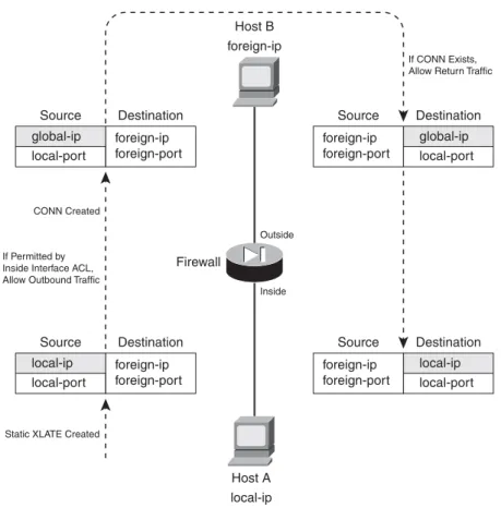
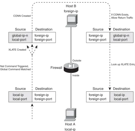
Address translation occurs on a one-to-one persistent basis. Each static translation that is configured causes a static xlate entry to be created. Figure 6-2 illustrates static NAT operation during an
outbound connection. Inside Host A is initiating a connection to outside Host B. Notice that only the real (local) IP address is being translated, as the source address in the outbound direction, and as the destination address in the inbound direction for return traffic.
Figure 6-2 Static NAT Operation Across a Firewall
You can use the following command to configure a static NAT entry:
A static NAT entry is created across the firewall interfaces named real_ifc (insidefor example) and mapped_ifc(outsidefor example). The real IP address real_ipis translated to the mapped IP address mapped_ip only when the firewall needs to forward a packet between the real_ifc and mapped_ifc interfaces. The addresses can be a single IP address (use netmask 255.255.255.255) or an entire
ASA, FWSM
Firewall(config)# static (real_ifc,mapped_ifc) {mapped_ip | interface} {real_ip [netmask mask]} [dns] [norandomseq] [[tcp] max_conns
[emb_limit]] [udp udp_max_conns]
PIX 6.3 Firewall(config)# static (real_ifc,mapped_ifc) {mapped_ip | interface} {real_ip [netmask mask]} [dns] [norandomseq] [max_conns [emb_limit]]
Firewall
Outside
If CONN Exists, Allow Return Traffic
CONN Created
Static XLATE Created If Permitted by Inside Interface ACL, Allow Outbound Traffic
Host B foreign-ip Host A local-ip Inside foreign-ip foreign-port Source Destination global-ip local-port foreign-ip foreign-port Source Destination local-ip local-port local-ip local-port Source Destination foreign-ip foreign-port global-ip local-port Source Destination foreign-ip foreign-port
IP subnet address (use netmaskwith the correct subnet mask). By default, if the netmaskkeyword is omitted, a host mask is assumed.
This command causes the address translation to be carried out regardless of the IP protocol or port number being used. If you need a static translation only for a specific UDP or TCP port number, you can define a static PAT entry with the following command:
Now the firewall translates the real_ip and real_port to the mapped_ip and mapped_port values. The firewall can inspect and alter DNS packets if the dnskeyword is added. If the real address is found in the packet, it is rewritten with the mapped address.
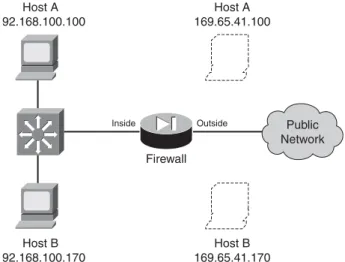
As an example, consider two hosts that reside on the inside of a firewall, using private IP addresses 192.168.100.100 and 192.168.100.170. Outbound connections from these hosts should appear as 169.65.41.100 and 169.65.41.170, respectively. Because the hosts must always receive the same mapped addresses, static NAT should be used. Figure 6-3 shows a network diagram for this scenario. Figure 6-3 Network Diagram for the Static NAT Example
The static NAT entries could be configured with the following commands:
Firewall(config)# static (inside,outside) 169.65.41.100 192.168.100.100 netmask 255.255.255.255 0 0
Firewall(config)# static (inside,outside) 169.65.41.170 192.168.100.170 netmask 255.255.255.255 0 0
ASA, FWSM
Firewall(config)# static (real_ifc,mapped_ifc) {tcp | udp} {mapped_ip |
interface} mapped_port {real_ip real_port [netmask mask]} [dns] [norandomseq] [[tcp] max_conns [emb_limit]] [udp udp_max_conns]
PIX 6.3 Firewall(config)# static (real_ifc,mapped_ifc) {tcp | udp} {mapped_ip |
interface} mapped_port {real_ip real_port [netmask mask]} [dns] [norandomseq] [max_conns [emb_limit]]
Host A 192.168.100.100 Host A 169.65.41.100 Host B 169.65.41.170 Firewall Outside Inside Host B 192.168.100.170 Public Network Section 6-2
The netmask is given as a host mask (255.255.255.255), because each translation is applied to a single host address.
To extend this example further, suppose inbound SMTP and HTTP connections to 169.65.41.100 could be sent to two separate inside hosts, each handling one of the two types of connections. Static PAT is a good solution for this scenario. With the following commands, SMTP connections are translated to inside host 192.168.100.100, while HTTP connections are translated to
192.168.100.200. An access list is also applied to the outside interface, to permit inbound SMTP and HTTP connections.
Firewall(config)# static (inside,outside) tcp 169.65.41.100 smtp 192.168.100.100 smtp
netmask 255.255.255.255 0 0
Firewall(config)# static (inside,outside) tcp 169.65.41.100 www 192.168.100.200 www
netmask 255.255.255.255 0 0
Firewall(config)# access-list acl_outside permit tcp any host 169.65.41.100 eq smtp
Firewall(config)# access-list acl_outside permit tcp any host 169.65.41.100 eq www
Firewall(config)# access-group acl_outside in interface outside
TIP Notice that the order of the two addresses is reversed from the order of the two interfaces, implying that the IP addresses should be different. If an inside host has an IP address that can appear on the outside without being translated, you can enter real_ipandmapped_ipas the same address.
However, you should do that only if you intend to permit inbound connections to that address. A static NAT defined with identical addresses creates an xlate entry that can allow hosts on the outside to access the inside host.
If no address translation is needed, a better solution is to use identity NAT (the nat 0 command) or NAT exemption (the nat 0 access-list command).
If inbound connections are not needed, you should define an identity NAT. Xlate entries are only created when connections are initiated from the inside, offering a more secure solution. If inbound and outbound connections should be allowed to initiate, NAT exemption is the better choice.
You can also configure a static NAT entry based on the mapped (global) firewall interface, even if its address is not known ahead of time. In that case, you can use the interfacekeyword to translate the address it pulled from a DHCP server. For example, the following command translates the outside interface address to the inside host address 192.168.100.100. No matter what IP address the outside interface has, the translation takes place with the correct value.
Firewall(config)# static (inside,outside) interface 192.168.100.100 netmask
Policy NAT
You can use policy NAT when real addresses need to be translated to several different mapped addresses, depending on a policy decision. An access list is used to trigger the address translation only when a match is permitted. Policy NAT can be configured in two ways:
•
A conditional staticcommand, where inside real addresses are translated to predictable mapped addresses, depending on the outcome of an access list. This form of translation can be used if inbound connections are expected and permitted to the inside hosts.•
A conditional natcommand, where inside real addresses are translated to different mapped addresses defined in globalcommands, depending on the outcome of an access list. Use this form if the inside hosts are only expected to initiate outbound connections; inbound connections to those hosts will not be allowed.You can use the following steps to configure a policy NAT: 1. Identify the translation policy:
Firewall(config)# access-list acl_name permit ip real-ip real_mask foreign_ip foreign_mask
An access list named acl_name is used to identify traffic by source (real_ip real_mask) and destination (foreign_ip foreign_mask). When an outbound packet triggers the permitstatement, a matching policy NAT staticornatcommand is also triggered. The real_ipaddress given here is the address that is ultimately translated. You can substitute the hostreal_ip keyword pair if the source is a single host.
You use foreign_ip andforeign_maskto define a destination host or a whole subnet on the public network. You can also substitute the hostforeign_ip keyword pair if the destination is a single host.
You can repeat this access-list command to define other source/destination combinations that trigger a matching static command.
2. (static Only) Define the staticcommand translation:
A conditional static NAT or policy NAT translation is defined across the firewall interfaces namedreal_ifc and mapped_ifc. Here, the mapped_ipaddress replaces the real_ip address matched in the access list named acl_name.
You can repeat this command to define multiple NAT policies. Each static command should reference a different access list.
ASA, FWSM
Firewall(config)# static (real_ifc,mapped_ifc) mapped_ip access-list
acl_name [dns] [norandomseq] [[tcp] max_conns [emb_limit]] [udp
udp_max_conns]
PIX 6.3 Firewall(config)# static (real_ifc,mapped_ifc) mapped_ip access-list
acl_name [dns] [norandomseq] [max_conns [emb_limit]]
3. (nat Only) Define the nat command translation.
a. Configure a global address:
Firewall(config)# global (mapped_ifc) nat_id {global_ip [-global_ip] [netmask
global_mask]} | interface
Global IP addresses are used as mapped or translated addresses, and are defined as a single address (global_ip) or a range of addresses (global_ip-global_ip). The global definition must be identified with a NAT ID nat_id(1 to 2,147,483,647), which is linked to nat com-mands with the same value.
The destination or mapped interface is given as mapped_ifc(outside, for example), com-plete with surrounding parentheses. Therefore, NAT occurs for traffic that matches a pol-icy and also exits this interface.
You can specify a subnet mask as global_mask, so that the firewall automatically excludes the network and broadcast addresses from the range of global addresses given. You can also use the interface keyword to use the mapped interface’s IP address as the global address. In this case, the translation is performed using PAT, as many real IP addresses could become translated to the single interface address.
b. Configure a NAT translation:
Define the NAT translation to occur at the local or real interface named real_ifc (inside, for example). The address translation will use mapped addresses defined in global com-mands using the same NAT ID nat_id as is given here.
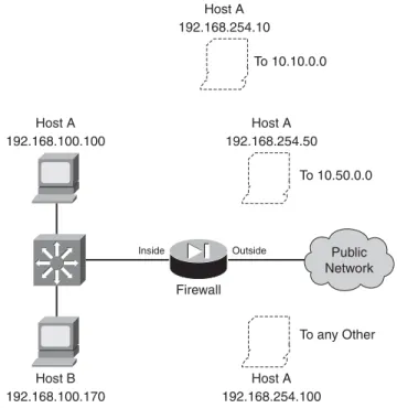
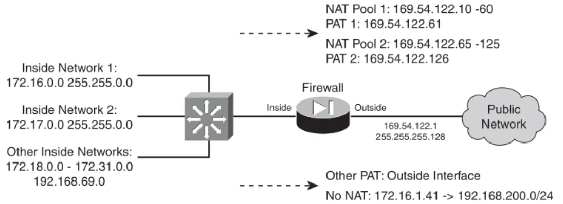
The translation only occurs if the extended access list acl_name matches a permit state-ment. You can match against source and destination addresses and port numbers. As an example, suppose two hosts reside on the inside of a firewall, using private IP addresses 192.168.100.100 and 192.168.100.170. Outbound connections from Host A should appear as different global addresses, depending on the destination of the connec-tion. The inside network interfaces with several different external business partners, each expecting Host A to reside in a different address space. This is a good application for pol-icy NAT, also called conditional NAT.
If Host A opens a connection to the 10.10.0.0/16 network, it should appear as global address 192.168.254.10. If Host A opens a connection to the 10.50.0.0/16 network, it should appear as 192.168.254.50. Lastly, if Host A opens a connection to any other desti-nation, it should appear as global address 192.168.254.100. Figure 6-4 shows a network diagram for this scenario.
ASA, FWSM
Firewall(config)# nat (real_ifc) nat_idaccess-list acl_name[dns] [outside] [[tcp]max_conns[emb_limit]] [norandomseq] [udp udp_max_conns]
PIX 6.3 Firewall(config)# nat (real_ifc)nat_idaccess-list acl_name[dns] [outside][norandomseq] [max_conns[emb_limit]]
Figure 6-4 Network Diagram for the Policy NAT Example
First, policy NAT using staticcommands is considered. The policy NAT entries could be configured with the following commands:
Firewall(config)# access-list hostApolicy10 permit ip host 192.168.100.100
10.10.0.0 255.255.0.0
Firewall(config)# static (inside,outside) 192.168.254.10 access-list
hostApolicy10 0 0
Firewall(config)# access-list hostApolicy50 permit ip host 192.168.100.100
10.50.0.0 255.255.0.0
Firewall(config)# static (inside,outside) 192.168.254.50 access-list
hostApolicy50 0 0
Firewall(config)# static (inside,outside) 192.168.254.100 192.168.100.100 netmask 255.255.255.255 0 0
If ACL hostApolicy10 matches and permits traffic, Host A is translated to
192.168.254.10. If ACL hostApolicy50 matches and permits traffic, Host A is translated to 192.168.254.50.
You might be inclined to define a third policy access list that denies the other two condi-tions, and then permits everything else. However, policy NAT will not accept an access list that contains deny statements; the idea is to permit the traffic where you need a transla-tion. Instead, you can use a regular static NAT (without an access list) to define the third condition. Now the inside address 192.168.100.100 has been defined in three different address translation commands. This works because the more specific static translations (policy NAT) are evaluated first, followed by regular static NAT.
Firewall Outside Inside Public Network Host A 192.168.100.100 Host A 192.168.254.50 Host A 192.168.254.100 To any Other To 10.50.0.0 Host A 192.168.254.10 To 10.10.0.0 Host B 192.168.100.170 Section 6-2
Finally, policy NAT with natcommands is used. You could use the following configura-tion commands:
Firewall(config)# access-list hostApolicy10 permit ip host 192.168.100.100
10.10.0.0 255.255.0.0
Firewall(config)# global (outside) 1 192.168.254.10 255.255.255.255
Firewall(config)# nat (inside) 1 access-list hostApolicy10
Firewall(config)# access-list hostApolicy50 permit ip host 192.168.100.100
10.50.0.0 255.255.0.0
Firewall(config)# global (outside) 2 192.168.254.50 255.255.255.255
Firewall(config)# nat (inside) 2 access-list hostApolicy50
Firewall(config)# access-list hostApolicy100 permit ip host 192.168.100.100 any
Firewall(config)# global (outside) 3 192.168.254.100 255.255.255.255
Firewall(config)# nat (inside) 3 access-list hostApolicy100
Traffic passing from host 192.168.100.100 to the 10.10.0.0/16 subnet, for example, matches the permit statement in access list hostApolicy10, which triggers the nat command with ID 1. This causes the inside host address to be translated to the address defined in global ID 1, 192.168.254.10.
Identity NAT
Identity NAT can be used when the real host and the mapped address are identical. In other words, the same IP subnet appears on both sides of the firewall. This is useful if you have registered IP addresses on the inside, and you have no need to translate them on the outside.
You can use the following command to configure an identity NAT:
Notice that the nat_id here is always zero. This is a special case of the translation policy, one that does not require a corresponding global command.
Recall that the static command can also set up an identity NAT, where the real address appears unchanged on the mapped side. In other words, no real NAT is taking place.
What is the difference between using staticand using nat 0, if both prevent NAT from occurring? When the static command defines an identity NAT, connections involving the real address can be initiated in both directions through the firewall (assuming the connections are permitted by access lists).
As soon as the staticcommand is entered, the firewall creates static xlateentries when the real hosts attempt outbound connections that are permitted through the firewall. Likewise, it is also possible
ASA, FWSM
Firewall(config)# nat (real_ifc)0 real_ip real_mask [dns] [norandomseq] [[tcp] max_conns [emb_limit]] [udp udp_max_conns]
PIX 6.3 Firewall(config)# nat (real_ifc)0 real_ip real_mask [dns] [norandomseq]
for outside hosts to reach the real hosts in the inbound direction, because the xlate entries will still be created.
If you define the same real host with a nat 0 command, that host can only initiate outbound connections. No inbound connections are allowed. Therefore, the nat 0command sets up a one-way path without translating the real address.
As a last note, you should avoid configuring both static and nat 0 commands for the same real addresses. It might seem logical to define both to prevent NAT from occurring, but the two methods are really mutually exclusive.
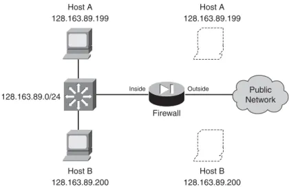
As an example, consider two hosts that reside on the inside of a firewall. The inside network uses a publicly registered IP subnet of 128.163.89.0/24. For this reason, no address translation is necessary, as the inside hosts can appear on the outside with publicly routable addresses.
An identity NAT can be used in this case. For example, Host A at 128.163.89.199 on the inside will also appear as 128.163.89.199 on the outside. In fact, the whole subnet will be defined in a similar manner. Figure 6-5 shows a network diagram for this scenario.
Figure 6-5 Network Diagram for the Static Identity NAT Example
If both outbound andinbound connections should be possible, you should consider using the nat 0
access-listcommand to define a NAT exemption. This is discussed fully in the next section “NAT
Exemption.” The NAT exemption entries for the whole subnet could be configured as follows:
Firewall(config)# access-list ExemptList permit ip 128.163.89.0 255.255.255.0 any
Firewall(config)# nat (outside) 0 access-list ExemptList
You should also configure the appropriate access lists to permit the inbound and outbound connections for this subnet.
128.163.89.0/24 Host A 128.163.89.199 Host A 128.163.89.199 Host B 128.163.89.200 Firewall Outside Inside Host B 128.163.89.200 Public Network Section 6-2
TIP Legacy PIX 6.3 platforms create xlate entries for each individual host contained in the identity NAT subnet. For large subnets, the number of static xlate entries can grow quite large. Beginning with ASA 7.0, the firewall builds a single xlate entry representing an entire subnet.
To configure the identity NAT for outbound use only, you could use the following command:
Firewall(config)# nat (inside) 0 128.163.89.0 255.255.255.0
The subnet mask, given as 255.255.255.0, defines the extent of the addresses that have identity translation entries. It also allows the firewall to prevent translations from being built for the network (128.163.89.0) and broadcast (128.163.89.255) addresses.
NAT Exemption
Sometimes you might have specific real (local) IP addresses that need to bypass NAT and appear untranslated. This might be needed only for individual IP addresses or for unique traffic flows. NAT exemption is similar to an Identity NAT, where the real and mapped IP addresses are identical. However, NAT exemption uses an access list to define a policy for bypassing translation.
Unlike identity NAT, which allows connections to be initiated only in the outbound direction, NAT exemption allows connections to be initiated in either the inbound or outbound direction.
NAT exemption is most often used in conjunction with VPN connections. Inside addresses might normally be translated for all outbound connections through a firewall. If a remote network is reachable through a VPN tunnel, the inside hosts might need to reach remote VPN hosts without being translated. NAT exemption provides the policy mechanism to conditionally prevent the address translation.
You can use the following steps to configure NAT exemption: 1. Define the policy with an access list:
Local addresses that are permitted by an entry in the access list are exempted from translation. Normally, you should only configure permitstatements as a part of the NAT exemption access list. (Although denystatements are allowed, you would really be defining conditions to deny when NAT should be denied!)
In addition, only the ipprotocol is allowed in the access list. NAT exemption is evaluated based on source and destination addresses—not on IP protocols or port numbers.
ASA, FWSM
Firewall(config)# access-list acl_name [extended] permit ip local_ip local_mask foreign_ip foreign_mask
PIX 6.3 Firewall(config)# access-list acl_name permit ip local_ip local_mask foreign_ip foreign_mask