Matthew Walker GENE – Sustainable Energy Concentration 6/15/20
Senior Project – Corrosion Prevention
Project Title: Corrosion Prevention
Project Sponsor: Pete Schwartz, Cal Poly Physics Objective:
Prevent cookers from breaking due to loss of electrical connection due to corrosion. Simplify the production process to reduce costs from labor hours and/or materials. Create a longer lasting, more durable cooker.
Description:
In Insulated Solar Electric Cooking (ISEC), heating is done by passing current through a chain of diodes directly connected to a solar panel (Gius et al, 2019). It is crucially important that the wires remain conducting, but not conduct to any metal surface that might short the heating circuit. Corrosion of any wires will cause a loosening of the mechanical (twisted) wire connection and could result in a loss of electrical connection completely, or undesired increased resistance.
Blankets for Insulation
Aluminum Heating Element Sleeve (cooker goes here)
Bucket A.K.A. “external casing”
Steam Vent
ISEC allows for low cost, low power solar panels (~ 100 W) to cook food over a long period during the day. A 100 W solar panel brings about 1 kg of water to a boil in one hour. Earlier ISEC models allowed for cooking to occur only while the sun is shining. More recent ISEC models store heat by melting a phase change material (PCM, erythritol, melting point ~ 118 C), providing two advantages:
- Increased power because the stored heat can be transmitted to food quickly with sufficient thermal conductivity.
- Ability to cook after the sun has set if the insulation is adequate to keep the PCM hot.
Between the outer and inner walls of the cooker resides the phase change material (PCM). This PCM is currently erythritol, which is electrolytic. On the heating element sleeve resides a diode-based heating element which optimally draws power from a panel.
If the diodes used (1N5408) reach a temperature near or above 270 °C they often become damaged, lowering their forward bias voltage, and otherwise causing the diode to behave like a resistor, or break completely, opening the circuit. Also, all diodes in general will last longer when kept at lower
temperatures. For these reasons it is important to thermally anchor the diodes to the heating sleeve. Having the food so close to the heat source (diodes) increases the maximum cooking temperature, which allows users to cook a wider variety of foods. Additionally, submerging the diodes directly in the PCM provides them with a heat sink, ensuring they stay well below 270 °C.
Challenges: Galvanic Corrosion, Electrolysis, Connections Galvanic Corrosion -
Galvanic corrosion (and nearly all types of corrosion) happens when two dissimilar metals are in direct physical contact or connected by a wire, and connected by an electrolyte. It is known to occur faster with heat. One metal becomes the anode, is oxidized (loses an electron and a metal ion), and the other metal becomes the cathode, and is reduced (gains an electron). The anode is the metal which will corrode the fastest. The cathode will corrode much slower. In the case of our cooker, diode lead wires are composed of single stranded tin coated copper and the lead wires are pure single stranded copper. Copper becomes the cathode and tin the anode. They are both in contact with the erythritol which is electrolytic. The metal that is more noble on the galvanic scale (A.K.A. galvanic series) always becomes the cathode. The anode (tin) will shed an electron and a tin ion. Therefore, tin will visibly disappear and deposit elsewhere, causing loosened connections. See the galvanic scale and diagram on the next page.
Galvanic corrosion is a naturally occurring phenomena and cannot be prevented but only slowed. There are three ways to slow galvanic corrosion. Below they are listed in order of effectiveness.
Sapper of the Cal Poly Chemistry department has offered us a generic clear epoxy which can be used to see corrosion without removing the epoxy. If connections with the Eric Sapper of CP Chemistry fall through, any clear epoxy which can withstand temperatures of 300 °C will work.
2. Use two metals that are as close together as possible on the galvanic scale, essentially leading to a smaller voltage to drive the current through the electrolytic solution.
3. Use two metals that are not only close together on the galvanic scale but also both as noble as possible.
Source: https://www.corrosionpedia.com/an-introduction-to-the-galvanic-series-galvanic- compatibility-and-corrosion/2/1403
Electrolysis –
Electrolysis is considered a form of corrosion and occurs when two metals connected by a wire are placed in an electrolytic solution and a voltage is applied. These two metals need not be different metals. The voltage source forces a non-spontaneous reaction to occur. The anode is whichever metal is connected to the positive lead from the power source. The anode will shed ions and electrons and deposit those ions elsewhere. If copper were the anode, it would shed copper ions. Those ions would react with other ions present in the erythritol to become more stable, and they would appear a green color. The green colored copper ions could deposit onto the same piece of metal they came from, or they could deposit elsewhere. See the diagram below. To prevent electrolysis, see steps below:
1. Remove the metals from the electrolytic solution by using a dielectric oil or coat the metals heavily with epoxy.
2. Remove or reduce the applied voltage.
As previously stated, no phase change materials are dielectric. Therefore, there is currently only one effective way for us to slow electrolysis in ISECs, which is by using epoxy.
Source: https://www.gcsescience.com/ex3.htm
Connections –
The best option we have now is a spot weld. We have attempted spot welding with a regular power source, and it has been unsuccessful, so a spot welder will be necessary for future connections.
Notes on broken cookers:
Evidence of both electrolysis and galvanic corrosion have been found in our cookers. Prior to the experiment detailed in the remainder of this paper, we had already tried the following construction methods with the following results.
- Soldered (and twisted) connections between tin coated copper diode leads and copper lead wires, as well as diode lead to diode lead connections submersed in erythritol. It is unclear if the solder melted or not, but the connection worked for a long period of time.
- Twisted connections between tin coated copper diode leads and copper lead wires, as well as diode lead to diode lead connections submersed in erythritol. These cookers usually stopped allowing current to flow within a few months of use. After being dissected, evidence of what is believed to be electrolysis was found. Figure 1 shows the notorious green color of corroded copper on the diode’s lead wire. The corrosion progressed through the tin coating and nearly to the center of the lead wire. The confusing issue is that sometimes this green color is found on the most positive lead, and sometimes on the negative lead. Generally, we would expect the green color to be found on only one lead. Another cooker constructed in this way allowed current to flow for only 1 day. Then next morning it mysteriously did not work, after working perfectly the night before.
- JB weld coated twisted connections between tin coated copper diode leads and copper lead wires, as well as diode lead to diode lead connections submersed in erythritol. These cookers held up the longest and showed little to no signs of corrosion when dissected.
- Twisted connections between tin coated copper diode leads and copper lead wires, as well as diode lead to diode lead connections immersed in concrete. These cookers broke within a month. Concrete is known to be highly corrosive.
Figure 1. Corroded diode lead of a cooker constructed by twisting all connections. Surrounding the diode is erythritol and JB weld. During construction, diode bodies were glued to the pot using JB weld, but
leads were left uncoated.
Experimental Procedures:
5 separate baths of diodes in erythritol connected in different ways were placed into a well-insulated cooler and heated until the erythritol melted for 4 hours per day, 3 days per week, for a total of 8 weeks. Eryithritol Bath 1 (see Figure 2): Applied current of 6A. Diode chain composed of single stranded copper leads connection to sanded copper diode leads on each end, then 5 tin (nonsanded) diodes for the middle of the chain. We suspected corrosion to occur here, but suspected it might not cause a loss of electrical connection.
Eryithritol Bath 2 (see Figure 3): Applied current of 6A. Single stranded copper leads, 5 diodes with sanded copper leads. We suspected no corrosion to occur here.
*Note: Between the chains in baths 2 and 3, a 150°C 10A temperature switch was connected. The negative copper lead wire of bath 2 and the positive copper lead wire of bath 3 were twisted onto the leads of the temperature switch to make the connection. This was later replaced with a 160 °C 16A switch after loss of electrical connection occurred at the switch. This is described in more detail in the experimental notes section.
Eryithritol Bath 3 (see Figure 4): Applied current of 6A. Single stranded copper leads, tin diode leads, with the whole chain coated in JBweld. We suspected no corrosion to occur here.
Eryithritol Bath 4 (see Figure 5): Appled current of 6A. Single stranded copper leads, tin diode leads, no JBweld coating. We suspected corrosion to occur quickly here.
These 4 baths were powered using a single power soure. The chains were put in series with 7A current. A “bath” consisted of a clear glass container filled with 250g of erythiritol and placed inside of a
Eryithritol Bath 5 (see Figure 6): There was no voltage or current applied. 3 items were placed in this bath: A single stranded copper wire and tin diode lead twisted directly together, a single stranded copper wire and sanded copper diode lead twisted directly together, a single stranded copper wire and tin diode lead twisted directly together and coated with JB weld. These three items never physically touched but were in the same bath of erythritol. We suspected corrosion to occur on copper and tin twisted together without JBweld.
Bath 5 was placed inside of the styrofoam cooler containing baths 1-4 and it heat at nearly the same rate. All bath temperatures were monitored by placing a thermocouple in the erythritol. They melted at nearly the same rate (all within half an hour of each other, bath 5 melting last) and reached nearly the same temperature (bath 5 about 10°C cooler than the rest). A thermal switch was glued onto a single aluminum plate that was underneath of all baths. Sand filled the bottom of the cooler to prevent fires.
Figure 4. Bath 3 before adding erythritol. Figure 5. Bath 4 before adding erythritol.
Figure 7. The cooler consisting of all baths filled with erythritol.
Experimental Notes:
- After running the above experiment for about 2 hours, the circuit opened. As shown in Figure 7, the erythritol was in powder form. When it melts for the first time it will drop to the bottom of the bath and leave a cavity of un-melted erythritol around the diodes, insulating them. A few diodes were damaged, so I rebuilt all 4 chains and refilled each bath with 250g of erythritol before restarting the experiment. When I did restart it, I agitated the erythritol by hand, so it was always in contact with the diodes.
while temperatures were near or above 150 °C. The switch only malfunctioned early in the day at low temperatures (below 120 °C), before the erythritol had melted. After disconnecting the power then reconnecting and attempting to pass only 1-2A of current through the switch, it would close the circuit again. I believe that the temperature switch was the cause of the open circuit during week 3. It is confusing to think that (after 9 weeks) corrosion caused bath 4 to open circuit when there is no sign of corrosion on the chain and it allows current to pass through normally.
- From the beginning of week 5 until the end of the experiment bath 1 experienced connectivity interruptions because of a loose connection between diode leads. The black coating was prominent. If I moved the chain around, I could usually get it to allow current to pass through temporarily while I held it in place. Twice during the remainder of the experiment, I had to remove the chain from bath 1, scrape off the black coating, and tighten the connections.
Results:
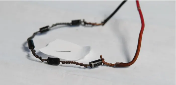
- Bath 1 (Figures 8-10): The chain with sanded copper leads on the most positive and negative connections only (not sanded, tin diode to diode connections) from bath 1 has a visible black coating which is thicker on the negative half of the chain (first 3 connections) than the positive half (last 3 connections). It allows current to pass, but as previously stated, needs to be held in a certain position from time to time, and has loose connections. It was also taken apart, cleaned with sandpaper, and put back together twice during the experiment. When preparing this chain, the tin was sanded by hand and there was still a small amount of tin near the diode body on the most positive and negative diode to lead connections (as well as tin covering each diode to diode connection). This small amount of tin near the diode body is still visible on the most negative diode to lead connection (Figure 8) but has corroded away on the most positive diode to lead connection (Figure 10). The tin is completely corroded away from the most positive diode to diode connection (Figure 10) and is completely intact on the most negative diode to diode connection (Figure 8). Both connections in between have some tin left but not all (Figure 9). This confirms our mental model of electrolysis as the anode (positive lead) has corroded away while the cathode (negative lead) has stayed intact.
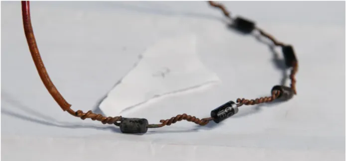
- Bath 2 (Figures 11-13): The chain with all leads sanded from bath 2 experienced a medium amount of corrosion. There is a black coating on portions of the leads between diodes. It is not a heavy layer. This black coating is assumed to be tin deposition and is attributed to the tin that is left behind when sanding by hand is not done perfectly. The connections are not loose.
- Bath 3 (Figures 14-16): The JB weld coated chain from bath 3 experienced no visible corrosion and still allows current to pass through normally.
the erythritol to remove the chains from their baths. Baths 4 and 5 were left in the oven the longest, potentially reaching 240 °C but not reaching a temperature high enough to have broken the diodes. The diode broke upon removing it from its bath with great force, because it had been taped to the bottom of the bath with gorilla tape.
- Bath 5 (Figures 19-21) the sanded and un-sanded diode (Figures 20 and 21, respectively) both have the same very small amount of black coating on portions of the leads. The JB weld coated diode (Figure 19) experienced no corrosion and looks pristine. NOTE: The broken lead in Figure 19 did not break during the experiment. After the experiment was over, all baths were placed in an oven to melt the erythritol to remove the chains from their baths. Baths 4 and 5 were left in the oven the longest, potentially reaching 240 °C but not reaching a temperature high enough to have broken the wires. The lead broke upon removing it from its bath with great force, because it had been taped to the side of the bath with gorilla tape.
- This black coating is likely deposits of tin ions that have bonded with elements within the erythritol.
- We did not see the green color we expected to see from corroded copper anywhere in this experiment.
Figure 9: Middle of chain from bath 1.
Figure 11. Negative end of chain from bath 2. This chain had all connections sanded to remove tin.
Figure 13: Positive end of chain from bath 2.
Figure 15: Middle of chain from bath 3.
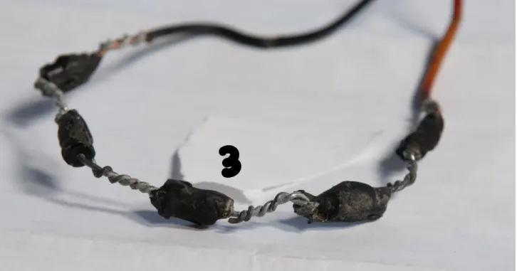
Figure 17: Negative end and middle of chain from bath 4. This chain was made with regular (not sanded) tin coated diode leads and copper lead wires.
Figure 19: JB weld coated diode from bath 5. Diode lead was broken after the experiment.
Figure 21: Diode with leads left not sanded (tin coated) from bath 5.
Interpretation:
- The lack of corrosion in bath 5, the deposits of tin on the negative lead in bath 4, and the disappearance of tin on the positive connections of bath 1 lead us to believe that the corrosion occurring in our cookers is mainly due to electrolysis. It could be that the combination of both electrolysis and galvanic corrosion in one bath accelerates corrosion more than if you added the two rates from separate baths together.
- The results seem to point to the JB weld coated chains (baths 3 and 5) as the best performer and the sanded copper diode leads only on each end of the chain (bath 1) as the worst performer.
- The corrosion of tin will cause connections to loosen over time. Tin essentially acts as a sacrifice, corroding before copper.
- Bath 4 would have likely corroded further and lost electrical connection if the experiment continued longer. It is unclear why bath 1 corroded faster than bath 4. Since corrosion in our cookers is now believed to be mainly due to electrolysis, and the speed of corrosion from electrolysis is determined by voltage (as well as conductivity of the solution) it is possible that a small difference in the forward bias voltage of the diodes could cause one bath to corrode faster than the others. In future experiments, the voltage across each diode chain should be
monitored.
the same size or get smaller. If appearing anywhere else, the green color should be a deposit of copper ions originating from the positive lead. This is the result of electrolysis.
- Electrolysis also causes tin to corrode. The color it would appear is unknown, but the pattern from above would be consistent – the positive lead should corrode and shrink in size or stay the same and the negative lead (or any other point on the chain) would increase in size or stay the same. It is possible that the black coating in the photos above is from tin deposits.
- Galvanic corrosion would cause tin to be corroded and deposited somewhere on the diode chain. The color is unknown and could be the black coating we see in several of the diodes following the experiment. This would not necessarily follow any pattern of occurring on the positive or negative lead as it occurs spontaneously (without an added power source).
Conclusion:
- Going forward I suggest we try nickel-plated lead wires and nichrome wire as the heating element for any resistive heater cookers and plated copper lead wires connected to tin-plated copper diode leads for any diode-based cookers. All connections should be spot welded together to avoid loose connections from corrosion. All connections would benefit from being coated in epoxy as opposed to being exposed to the erythritol. Fiberglass insulation surrounding any wires should do the same as epoxy, so long as there is no way for the erythritol to seep in. For example, the fiberglass insulation will be stripped from the end of the nickel-plated lead wires to allow them to be spot welded to the nichrome wires. Where the wire is stripped, epoxy should be applied to completely cover that area after spot welding. This will lead to the most durable, long lasting cooker.
- Nickel-plated lead wires and nichrome wire should work well in this corrosive environment because their potential difference on the galvanic scale is small and their position on the scale is (more towards) noble. To test their ability to withstand this corrosive environment, one could repeat the experimental procedure above with the following changes and notes:
o Run the experiment for a total of ~200 hours, counting those hours only when the erythritol is melted. As shown above, about 50 hours of time (if counting only those where the erythritol was melted) was not.
o Monitor the voltages of each bath, ensuring they stay close to each other. The voltage across the positive and negative lead wires of each bath is one of the two main driving forces of electrolysis and should be monitored. The other main driving force of
electrolysis is the conductivity of the solution, so be sure to use erythritol from the same supplier in each bath. Ensure all parts of the wire or chain in question are submerged in the erythritol for the entire experiment.
o It does not matter whether wires are single-stranded or multi-stranded. It should be consistent between baths so that all baths have the same type of wire (approximately the same number of strands). This is important because if there are 25 strands of tin-plated wire for example, the plating on each strand of wire will be much thinner than a single stranded wire.
o Bath 2: Copper lead wire to tin plated copper diode leads. Spot weld all connections. Expect to see corrosion here same as above. Tin may deposit on the negative copper lead wire.
o Bath 3: Tin-plated copper lead wire to tin plated copper diode leads. Spot weld all connections. Coat entire chain in JB weld. Wait until JB weld cures, then coat again to ensure erythritol cannot contact the chain. Expect no corrosion here.
o Bath 4: Nickel-plated fiberglass insulated lead wires to nichrome wire. Spot weld all connections. Coat any non-insulated portions of either wire with JB weld. Expect no corrosion here. This will test the effectiveness of the fiberglass insulation in slowing corrosion.
o Bath 5: Nickel-plated lead wires to nichrome wire. Spot weld all connections. Do not cover in fiberglass insulation. Coat entire length of both wires in JB weld. Expect no corrosion here. This will serve as a comparison for bath 4.
o Bath 6: Nickel-plated lead wires to nichrome wire. Spot weld all connections. Do not cover in fiberglass insulation. Do not coat in JB weld. Expect corrosion here. This will serve as a comparison for bath 4.
Acknowledgments: