VTT PUBLICATIONS 479
A Software Architecture for
Configuration and Usage of Process
Simulation Models
Software Component Technology and
XML-based Approach
Tommi Karhela
VTT Industrial Systems
Dissertation for the degree of Doctor of Technology to be presented with
due permission for public examination and debate at Helsinki University of
Technology (Espoo, Finland) in Auditorium T2 (Konemiehentie 2, Espoo)
on the 11
thof December, 2002 at 12 noon.
ISBN 951–38–6011–6 (soft back ed.) ISSN 1235–0621 (soft back ed.)
ISBN 951–38–6012–4 (URL:http://www.inf.vtt.fi/pdf/) ISSN 1455–0849 (URL:http://www.inf.vtt.fi/pdf/ )
Copyright © VTT Technical Research Centre of Finland 2002
JULKAISIJA – UTGIVARE – PUBLISHER VTT, Vuorimiehentie 5, PL 2000, 02044 VTT puh. vaihde (09) 4561, faksi (09) 456 4374 VTT, Bergsmansvägen 5, PB 2000, 02044 VTT tel. växel (09) 4561, fax (09) 456 4374
VTT Technical Research Centre of Finland, Vuorimiehentie 5, P.O.Box 2000, FIN–02044 VTT, Finland phone internat. + 358 9 4561, fax + 358 9 456 4374
VTT Tuotteet ja tuotanto, Tekniikantie 12, PL 1301, 02044 VTT puh. vaihde (09) 4561, faksi (09) 456 6752
VTT Industriella System, Teknikvägen 12, PB 1301, 02044 VTT tel. växel (09) 4561, fax (09) 456 6752
VTT Industrial Systems, Tekniikantie 12, P.O.Box 1301, FIN–02044 VTT, Finland phone internat. + 358 9 4561, fax + 358 9 456 6752
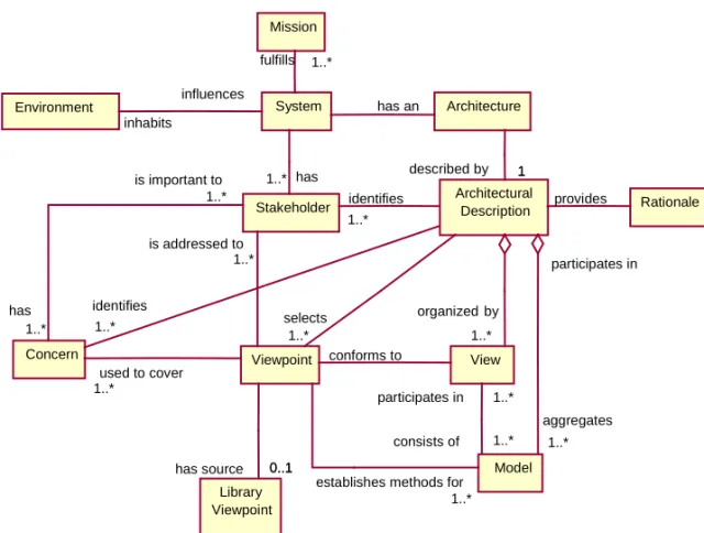
Figure 4.1 reprinted with permission from IEEE Std 1471-2000 "IEEE Recommended practice for architectural description of software-intensive systems" Copyright 2000, by IEEE. The IEEE disclaims any responsibility or liability resulting from the placement and use in the described manner.
Karhela, Tommi. A Software Architecture for Configuration and Usage of Process Simulation Models. Software Component Technology and XML-based Approach. Espoo 2002. Technical Research Centre of Finland, VTT Publications 479. 129 p. + app. 19 p.
Keywords process simulation, software architecture, XML, software component technology, model configuration
Abstract
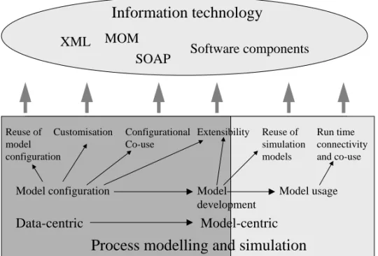
Increased use of process simulation in different phases of the process and automation life cycle makes the information management related to model configuration and usage more important. Information management increases the requirements for more efficient model customisation and reuse, improved configurational co-use between different simulators, more generic extensibility of the simulation tools and more flexible run-time connectivity between the simulators and other applications.
In this thesis, the emphasis is on large-scale dynamic process simulation of continuous processes in the power, pulp and paper industries. The main research problem is how to apply current information technologies, such as software component technology and XML, to facilitate the use of process simulation and
to enhance the benefits gained from using it. As a development task this means
developing a new software architecture that takes into account the requirements of improved information management in process simulation. As a research objective it means analysing whether it is possible to meet the new requirements in one software architecture using open specifications developed in information and automation technologies.
Process simulation is analysed from the points of view of standardisation, current process simulation systems and simulation research. A new architectural solution is designed and implemented. The degree of meeting the new requirements is experimentally verified by testing the alleged features using examples and industrial cases.
The main result of this thesis is the design, description and implementation of a new integration architecture for the configuration and usage of process simulation models. The original features of the proposed architecture are its openness, general distribution concept and distributed extensibility features.
Preface
My first contact to process simulation was when I was a summer student at the European Laboratory for Particle Physics (CERN) 1995. Later on at the beginning of 1996 I started to do my master’s thesis at VTT. At that time I was still more interested in developing simulation algorithms than focusing on the used simulation platform solutions. After graduating I had an opportunity to work in a simulation platform development project P21 (Simulation platform of 21st century) and later on this work was continued in the Gallery (Process model and parameter gallery for process integration) and Advice (Advanced Integrated Component based Simulation Environment) projects. The research and development done in these three projects form the background for the software architectural approach presented in this thesis.
I want to thank my supervisor, Professor Kari Koskinen, and my instructor, Dr. Jari Hämäläinen, for their support and tutoring during the writing process of the thesis. I am also thankful to my group leader, Mr Kaj Juslin, and to the entire system dynamics group at VTT Industrial Systems for the homely and innovative atmosphere they have provided. I want to express my gratitude to Mr Kalle Kondelin, Mr Matti Paljakka, Mr Pasi Laakso, Mr Teemu Mätäsniemi, Mr Jyrki Peltoniemi and Ms. Marja Nappa, especially, for all the discussions that have been essential when developing the ideas of the thesis. I am also grateful to Professors Seppo Kuikka and Kai Koskimies from the Tampere University of Technology for providing expert criticism and suggestions for the thesis. For the financial support, I express my gratitude to VTT, National Technology Agency and the Fortum foundation.
I also want to thank all my friends, especially Mr Sami Majaniemi for all the support, humor and relaxation they have brought to my life. Finally, my warmest thanks to my wife, to my parents and to my sister’s family for all the love and support they have given me over the years.
Espoo, October 12th 2002,
Contents
Abstract ... 3 Preface ... 4 Abbreviations... 8 Glossary ... 12 1. Introduction... 151.1 Motivation and background... 15
1.2 The objectives and hypotheses of the study ... 17
1.3 Research approaches and methods ... 19
1.4 Results and Contributions... 20
1.5 Structure of the thesis ... 21
2. Related Topics in Simulation, Process and Automation Technologies ... 23
2.1 Introduction ... 23
2.2 Related standardisation and specifications ... 24
2.2.1 CAPE-Open... 24
2.2.2 High Level Architecture (HLA) ... 27
2.2.3 Standard for the Exchange of Product Model Data (STEP).... 29
2.2.4 Product Data Markup Language (PDML)... 33
2.2.5 OLE for Process Control (OPC)... 34
2.3 Current Process simulation systems ... 37
2.3.1 Introduction ... 37
2.3.2 Apros/Apms ... 40
2.3.3 CADSIM Plus ... 42
2.3.4 Hysys... 44
2.3.5 Summary ... 46
2.4 Related research and development ... 47
3. Research and Development Problem ... 50
3.1 Introduction ... 50
3.2 Need for better model reuse and easier customisation ... 51
3.5 Need for more flexible run time connectivity ... 56
4. Proposed Architectural Solution ... 58
4.1 Introduction ... 58
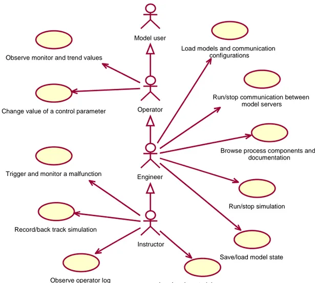
4.2 Use case analyses ... 60
4.2.1 Kernel developer ... 60 4.2.2 Provider ... 62 4.2.3 Model configurator... 63 4.2.4 Model user... 64 4.3 Viewpoints... 66 4.4 Logical view ... 68 4.4.1 Rationale ... 71 4.5 Data view... 72 4.5.1 Basic elements... 74
4.5.2 Component type description mechanism ... 75
4.5.3 Client and server extension description mechanism ... 76
4.5.4 Connection mechanism ... 77
4.5.5 Mapping mechanism ... 77
4.5.6 Documentation and history mechanisms... 79
4.5.7 Graphical descriptions... 79
4.5.8 Monitor, trend and state definitions ... 80
4.5.9 Data model of data connection... 81
4.5.10 References to other specifications... 82
4.6 Security view ... 84
4.7 Component view... 85
4.8 Process view ... 89
5. Verification ... 93
5.1 Introduction ... 93
5.2 Verification of the configurational features... 94
5.2.1 Model customisation using manufacturer data and dimensioning tools ... 94
5.2.2 Model reuse using centralised repository and parametricized construction ... 98
5.2.3 Co-use of a steady state simulator and a dynamic simulator 102 5.2.4 Empirical models in the architecture... 106
5.3.1 DCS testing ... 108
5.3.2 Training simulator support ... 111
5.3.3 Speed and scalability of the data change... 115
6. Discussion... 119
References... 123 Appendices
Appendix A: An example of EXPRESS language and late and early binding Appendix B: An example of the usage of the data model
Abbreviations
ACL Apros Communication Library
AE Alarms and Events
AIChE American Institute of Chemical Engineers
AP Application Protocol
API Application Programming Interface
CAD Computer Aided Design
CAPE Computer Aided Process Engineering
COM Component Object Model
CORBA Common Object Request Broker Architecture
DA Data Access
DCOM Distributed Component Object Model
DCS Distributed Control System
DDE Dynamic Data Exchange
DLL Dynamic Link Library
DMSO Defense Modeling and Simulation Office
DoD Department of Defence
DTD Document Type Definition
DX Data Exchange
EL Ecosim Language
FOM Federation Object Model
GML Gallery Markup Language
GQL Gallery Query Language
GTP Gallery Transfer Protocol
GUID Globally Unique Identifier (see UUID)
HDA Historical Data Access
HLA High Level Architecture
HPGL Hewlett-Packard Graphic Language
HTTP Hyper Text Transfer Protocol
HTTPS Hyper Text Transfer Protocol Secure
IDL Interface Definition Language
IEEE Institute of Electrical and Electronics Engineers
IIS Internet Information Server
ISO International Standard Organisation
I/O Input/Output
ModL Modeling Language of Extend platform
MOM Message Oriented Middleware
MSM Model Server Manager
MSTL Model Server Transport Layer
NPSHa Net Positive Suction Head Available
OLE Object Linking and Embedding
OMG Object Management Group
OMT Object Model Template
OPC OLE (Object Linking and Embedding) for Process Control
PC Personal Computer
PDML Product Data Markup Language
PDPD Phenomenon Driven Process Design
P&ID Process and Instrumentation Diagram
pdXi Process Data Exchange Institute
RPC Remote Procedure Call
RTI Run Time Infrastructure
SCADA Supervisory Control And Data Acquisition
SGML Standard Generalized Markup Language
SOAP Simple Object Access Protocol
SSL Secure Socket Layer
STEP Standard for the Exchange of Product Model Data
SVG Scalable Vector Graphics
TCP/IP Transmission Control Protocol / Internet Protocol
TEMA Tubular Exchanger Manufacturers Association
TLS Transport Layer Security
UI User Interface
UML Unified Modeling Language
UUID Universaly Unique Identifier
VMS Virtual Memory operating System (currently called OpenVMS)
Glossary
Architecture – See Software architecture
Component – See Process component
Data-centric approach
A point of view to process modelling and simulation where the emphasis is on the configurational data of a simulation model i.e. on topology and parameter values. The term is used (not rigorously defined) in CAPE-Open specification (CAPE-Open 2000).
First principle model
Model that is based on fundamental physical and chemical laws. Model-centric approach
A point of view to process modelling and simulation where the emphasis is on the model development and model interoperability. The term is used (not rigorously defined) in CAPE-Open specification (CAPE-Open 2000).
Model configuration
A definition of (or a work process of describing) the interconnections, parameter values and a set of specified initial states of process components that are needed to initialise a process simulation.
Model customisation
A process of setting the proper values for the parameters of a process component inside a model configuration.
Model development
A work process of programming separate unit operation models or other numerical solution algorithms that can be used together with some process simulator(s).
Model resolution
Model usage
Work process of using an already configured process model. During model usage the user starts and stops the simulation, observes the values and changes the set point values, but he does not make any changes to the model configuration.
Process
Sequence of chemical, physical or biological operations for the conversion, transport or storage of material or energy (ISO 1997b).
Process component
A physical object that is or may be a part of a process. Process model
A mathematical model of one or more interconnected process components. An experiment can be applied to a process model in order to answer questions about the process.
Process modelling
Constructing a process model. Includes both model configuration and model
development i.e. defining process structure and behaviour. Process simulation
An experiment made with a process model.
Process simulation model – see Process simulation
Process simulation tool – see Process simulator
Process simulator
A program that can be used for process modelling and simulation. Simulation scheme
The type of the major algorithm inside a process simulator. Can be for example sequential modular, equation-based, sequential and non-sequential modular or modular hierarchical (CAPE-Open 2000).
Software architecture
The fundamental organization of a system embodied in its (software) components, their relationships to each other, and to the environment, and the principles guiding its design and evolution (IEEE 2000).
Software component
A Reusable, executable, self-contained piece of software, which is accessible only through well-defined interfaces (Kuikka 1999).
Topology
Interconnections between process components. Unit operation
Specified process functions that perform one or more defined transformations on process stream(s).
1. Introduction
1.1 Motivation and background
Dynamic process simulation has traditionally been a tool for a researcher or a specialist to study and troubleshoot process and automation behaviour. Recent development, however, has made the process simulation tools also more suitable for everyday engineering. Tool development has mainly been possible due to the
rapid progress in hardware and software technology. Therefore, process
simulation and information technology used within the process simulation have
become an important research subject in the fields of process and automation
technologies.
Process simulation is a wide concept and can be interpreted in many ways. The
scope of the process simulation may vary from the simulation of micro-scale phenomena to the simulation of entire industrial plants. Industrial processes can also be divided into continuous and discrete processes or combinations of these. Furthermore, the chosen process simulation approach can be roughly divided into dynamic simulation and into steady state simulation. The industrial application domain may also differ. Given these criteria for process simulation it can be said that in this thesis the emphasis is on large-scale dynamic simulation
of continuous processes of the power, pulp and paper industry.
Process integration means systematic and general methods for designing
integrated production systems, ranging from individual processes to whole sites, with special emphasis on the efficient use of energy and reduction of the environmental effects (IEA 1993). This is the original definition of process integration research. The definition as it is stated includes already process simulation methods as part of process integration research. In some cases the definition is also expanded to cover information management methods. In process simulation research, information management methods can be
interpreted to cover the development of model reuse, customisation and
configurational co-use mechanisms. In this work, the process of finding and
setting the proper values for the parameters of the unit operation model is called model customisation or simply customisation. Parameters do not have to be only separate values describing physical and chemical properties but they can also be,
e.g., points of a characteristic curve or coefficients of a function describing that curve. In current simulation tools the reuse and customisation mechanisms are not always as efficient as they should be. In practice, process and automation designers often have to model and customise the same sub-processes and equipment for the process simulator over and over again.
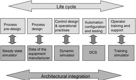
Life cycle consideration has become an important topic for the research in the
fields of process and automation technology (Lu et al. 1997; Ajo et al. 2001). Process simulation can already be used in the pre-design stage. It can be further
developed during the actual design stage. Simulation-assisted automation testing
is possible for an automation application using a dynamic simulation model and
the same model can be used for operator training. Furthermore, the model can
then be used in the mill after the start-up for offline operator support. Offline operator support could include, e.g., testing an unusual operational action with the simulation model before applying it to the real process. The problem with life cycle reasoning in process simulation is that the same tool should support all these different stages. This would require models of different resolution in different stages and easy enough transition from one stage to another.
Concurrent engineering aims to rationalise the process design project by
organising the traditionally sequential stages in parallel (Banares-Alcantara 2000). It has been stated for example that process and automation could be and should be designed simultaneously (Bogle 2000). According to Koolen, dynamic simulation is the key to this integration (Koolen 1998). However, the
interoperability of the dynamic process simulation tools and distributed control
systems (DCS) has to be further developed to fully realise the benefits from the integration. In order to verify the actual control schemes and logic running in
DCS against a dynamic simulator, flexible and fast enough run-time connectivity
is needed. Furthermore, if the control application definitions are to be shared between the simulator and DCS, for example in a training simulator project, there should be a way to transform the definition from one system to another. While software technologies are developing further, software architectures are becoming more open and more extensible. This is also a trend in simulation. CAPE- Open and HLA (High Level Architecture) specifications are examples of such a development (CAPE-Open 2000; HLA 2000). These specifications are,
blocks that can be attached to the execution of the simulation engine or run-time
infrastructure. On the other hand, there are also more data-centric
standardisation efforts (ISO 1998; Shocklee et al. 1998). The data-centric specifications are often large and concentrate mainly on conceptual design and product data management rather than on architectural issues.
The progress in software technologies offers possibilities for new kind of
integration of simulation tools. For process simulation, integration means reuse
of model configurations and parameter values, co-use of different simulation
tools, easy extensibility of simulator functionality and closer interoperability between distributed control systems and dynamic process simulators. In order to achieve this kind of integration, a domain specific architectural specification is needed. The specification should take into account both data-centric and model-centric requirements. The main research problem of the thesis is therefore how to apply current information technologies to facilitate the use of process simulation
and to enhance the benefits gained from using it. As a development task this
means developing a new software architecture for configuration and usage of
process simulation models. The research problem of the thesis is analysed in more detail in Chapter 3.
1.2 The objectives and hypotheses of the study
The main goals of this study are to define a software architecture that satisfies the reuse, customisation, co-use, extensibility and run-time connectivity needs of the process simulation domain and to test the validity of the hypotheses defined
below. The testing is done by constructing a prototype software system and
using examples and industrial cases to verify the expected features of the
architecture.
From the data-centric point of view, reuse and easy model customisation can be most easily achieved if all the users of the simulation environment can share the
model configurations. A centralised repository in the Internet would satisfy
these needs. The configurations themselves are structural containing process
equipment descriptions and their parameter values. This naturally leads to the
use of a structurally oriented description language, such as XML (Extensible
simulation tools and the fact that the centralised repository is located in the
Internet lead to the deployment of some message oriented middleware (MOM)
for example a protocol such as SOAP (Simple Object Access Protocol) (W3C
2000a).
From the model-centric point of view, extensibility can be most easily achieved
by applying software component technology. This way, the extended
functionality is well encapsulated and can be described using a component
description mechanism. Flexible and fast enough run-time connectivity are
requirements that can be satisfied by using software component technology and by utilizing a domain specific standard, e.g., OPC (OLE for Process Control).
There are two hypotheses in this study. Firstly, the same software architecture
can be used for sharing models between process simulation users, for facilitating
the model customisation and for co-using different process simulation tools.
Secondly, a flexible and fast enough run-time connection between a dynamic process simulator and a virtual DCS can be achieved using software component technology and a standardised interface, e.g. OPC. The chosen techniques will
be shown to be sufficient for simulation-assisted automation testing and for
operator training. Virtual DCS here refers to a process station that runs in an
ordinary PC.
In the second hypothesis it should be noted that several scalable and fast enough connections between dynamic simulators and control systems have been realised
over the years. However, these connections have been tailored between a certain
simulator and control system. The verification will show that configurational flexibility in the data connection and vendor independence can be achieved
using a standardised approach and still the speed and scalability will remain
adequate for small to medium size automation deliveries.
The reuse and model customisation mechanisms have to be developed further in order to make dynamic process simulation tools more suitable for everyday engineering. Until now the models have mainly been reused by copying
previously developed models from old projects. This kind of a template-based
approach will be further extended in this work by storing the models and
sub-models into a centralised repository in the Internet. Furthermore, the same
components easier. Process equipment manufacturers can store equipment data in the same repository and this data can be used in the simulation environment for setting the parameter values for an individual process component (5.2.1). In addition to the template-based reuse, a parametricised creation mechanism for structural components will be developed. Instead of copying the content of a
structural process component the content can be created using a user-defined
parametricised construction mechanism (5.2.2).
The co-use of different simulation tools is needed when changing from one project stage to another. As mentioned in Section 1.1, models of different resolution are needed in different stages. Usually one simulator does not support all the needed resolutions or different simulation tools are simply better suited for a specific stage. This implies that a transition from one model to another
would be useful. Such a transformation procedure will be created and its
usefulness analysed in the suggested architecture (5.2.3).
Better run-time connectivity between a dynamic process simulator and a DCS is needed in order to achieve flexible simulation-assisted automation testing and operator training. The performance of the connection is sufficient when the
entire control application can be tested in one go and the simulation can be run
at least in real time. Sufficient also means that the frequency of the
communication is adequate for testing all of the desired automation
functionality. Such a flexible and fast enough connection will be presented in the
suggested architecture. The different architectural choices that led to the suggested solution will also be analysed (5.3.3).
1.3 Research approaches and methods
The process simulation domain is studied from the angles of standardisation (CAPE-Open 2000; HLA 2000; ISO 1998), current process simulation systems (Apros 1999; CadsimPlus 2001; Hysys 2000) and simulation research. The
literature study covers the most relevant topics related to the architectural
development of this work. When studying current process simulation systems, three different simulators are selected as a reference set. The study is carried out
by answering to the same set of questions for each simulator. The questions are
to the above-mentioned connectivity, extensibility, co-use, reuse, and customisation. On the other hand, the questions will also probe the architectural issues related to the studied simulation systems.
The proposed solution to the formulated research problem is designed and
implemented. The hypothesis related to the model configuration is
experimentally verified by testing the features using example design cases. The
run-time connectivity features are verified using a set of industrial cases where the proposed solution is applied.
1.4 Results and Contributions
The main results of this thesis are the design and description of a new integration architecture for the configuration and usage of process simulation models and the application of current information technologies to implement such an architecture. Furthermore, it will be shown that:
1. More efficient model reuse and customisation can be achieved with the
proposed architecture if model configurators and equipment manufacturers share data in a centralised repository (example cases 5.2.1 and 5.2.2)
2. The developed architecture can be used for integrated use of different
simulation tools. In practice, the integrated use depends heavily on the simulator tool vendors and their willingness to support such architecture (example case 5.2.3).
3. Flexible and fast enough run-time connectivity between a dynamic process
simulator and a virtual DCS is achieved using OPC as a standard data exchange interface (industrial cases 5.3.1 and 5.3.2).
The original features of the proposed architecture are its openness, general distribution and distributed extensibility features. Both configurational and data connections are based on open ‘de-facto’ standards (XML, SVG, SOAP and OPC). The fact that the whole data model of the architecture, including graphics, model topology and parameter values, is represented in the same open format, opens up the possibilities for better reuse, customisation and configurational
co-use. The general distribution features offer possibilities to use simulation and simulation configuration resources regardless of where they are located in the Internet. The security model of the architecture is also designed to meet the requirements originating from the general distribution. Furthermore, the architecture can be extended in a distributed manner. New simulation tools can be linked to the architecture and configurational extension software components can be developed in one place and distributed through a centralised server in the Internet.
The research and development work of this thesis was carried out at VTT
Industrial Systems (VTT Automationuntil the end of 2001) within the P21 and
Gallery projects, both of which also included other work not reported in this thesis. The author participated in the requirement analyses of the architecture with other members of the project team (5 persons). He is responsible for the design and description of the architecture and for the implementation of the OPC Server and model configuration client tools (Model Explorer, MCKit).
1.5 Structure of the thesis
The thesis consists of six chapters.
Chapter 1. Introduction. Background and motivation, scope, the main research
problem, objective and hypotheses, research methods, main results, contribution and original features of the study are represented.
Chapter 2. Related Topics in Simulation, Process and Automation Technologies. Literature study of the state of the art is carried out in terms of simulation standardisation, state of the art in simulator tools and related academic research. Both model-centric and data-centric specifications are studied. HLA and CAPE-Open are studied as examples of model-centric specifications. STEP and PDML are studied as examples of data-centric specifications. The OPC specification is introduced as it has an important role in the prototype implementation of the proposed architecture. The study of the state of the art of the simulators is carried out by answering to an identical set of questions for a set of simulators. First, the different features of the process simulation tools are discussed. Three
simulators are selected for closer inspection. Finally, different modelling languages and other related research is represented.
Chapter 3. The Research and Development Problem. The research and
development problem is analysed in more detailed. The requirements of customisation, reuse, co-use, more generic extensibility and run-time connectivity are analysed in separate sections.
Chapter 4. Proposed Architectural Solution. The proposed architecture is
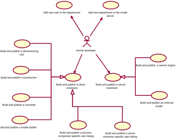
described using the practise recommended in IEEE-1471. First, the stakeholders and their concerns are identified using use case analyses. Then the viewpoints for the architectural description are selected. Logical view, data view, security view, component view and process view are described in separate sections.
Chapter 5. Verification. The alleged features of the architecture are verified.
This chapter represents the deployment view of the proposed architecture. Different use scenarios, each of which has a certain physical deployment, are represented in their own sections. First, use scenarios for verification of the configurational features of the model of the proposed architecture are represented followed by an introduction of the use scenarios verifying the model usage features.
Chapter 6. Discussion. The reliability, validity, unique features and generality of
2. Related Topics in Simulation, Process
and Automation Technologies
2.1 Introduction
The information technological approaches that are used in the modelling and
simulation have developed over the years. In this chapter, the state of the art of these approaches is studied. First, the related standardisation and specifications are probed. Then, the state of the art of the current simulation tools is analysed by studying a set of commercial process simulators. Finally, a review of other related research is performed.
A system is a potential source of data (Zeigler 1976). An experiment, on the other hand, is the process of extracting data from a system by exerting it through its inputs (Cellier 1991). In this work, the process model and process simulation are defined as follows:
A process model is a mathematical model of one or more interconnected process components. An experiment can be applied to a process model in order to answer questions about the process.
Process simulationis an experiment made with a process model.
A process simulator or a process simulation tool is a program that can be used for process modelling and simulation. The scale of the process model in the definition is defined as one or more interconnected process components.
However, the emphasis in this work is on large-scale process simulation. Large
scale means typically tens or hundreds of interconnected process components. The scope of mathematical modelling and simulation is broad in the process
industry. On the micro-scale level, the process industry may use molecular
modelling methods, on meso-scale level some process simulation tools and on
the macro-scale level some process synthesis and strategic planning methods
(Klemola & Turunen 2001). The emphasis in this work is on meso-scale to macro-scale modelling and simulation. On these levels, process simulation is used for process and automation design, control system testing, operator
training, plant operation optimisation, process reliability and safety studies, process improvements, and for start-up and shutdown analyses.
Industrial processes can be divided into continuous and discrete processes. The process simulation covered in this work is limited to the simulation of continuous processes. Furthermore, the simulation of continuous processes can be divided into steady state and dynamic simulation. The main emphasis in this work is on dynamic simulation, but most of the analyses done about reuse, customisation, co-use, extensibility and even run-time connectivity can be also applied to steady state simulation.
The field of process industry is broad covering such sectors as water treatment, food industry, pharmaceutical industry, energy industry, metallurgical industry, pulp and paper industry, oil refining industry and so forth. The main emphasis in this work is on modelling and simulation of the processes of the energy and pulp
and paper sectors. However, many of the results are generic and are applicable
also to other fields.
2.2 Related standardisation and specifications
2.2.1 CAPE-Open
The CAPE-Open specification defines the interfaces of software components of a process simulator. The specification was developed in a project sponsored by the European Community running from January 1997 to June 1999. The project goal was to enable native components of a simulator to be replaced by those from another independent source or part of another simulator with a minimum of effort. Several operating companies, simulator vendors and academic institutions participated in the project (CAPE-Open 2000). Currently the CAPE-Open specification is maintained by the CAPE-Open laboratories network (Co-LaN 2002).
CAPE-Open defines a process simulator (known as a flowsheet simulator in the CAPE-Open specification) as a tool that is used in order to create models of the manufacturing facilities, processing and/or transformation of materials. The specification divides process simulators into categories according to the internal
architecture or type of the simulator. Both terms are easily misinterpreted and thus the internal architecture is referred to as a simulation scheme in this work. The specification names four different simulation schemes: sequential modular, equation-based, sequential and non-sequential modular, and modular hierarchical. The sequential modular scheme is the most common of these schemes. The given properties of the input stream (flow, temperature) and the process unit are used for the derivation of the properties for the output stream. These output properties then act as an input stream specification for the next process unit. This sequence is continued until the last process unit is reached. An example of a process simulation tool using this approach is Aspen Plus (AspenTech 2002). In the equation-based approach every model equation of the process system is solved simultaneously. The number of equations used increases considerably with the size of the process plant. Asimulating tool using this approach is e.g. Apros/Apms (Apros 1999). The third category is a hybrid solver often used in simulators meant for both steady state and dynamic simulation. CADSIM Plus (CadsimPlus 2001) is an example of a hybrid solver. The modular hierarchical scheme in the CAPE-Open specification refers most likely to simulators where the solved modules form hierarchical structures. However, the specification does not specify this scheme any further nor does it give any examples of simulators using this scheme.
The specification defines common functionality for all simulation schemes. These ‘conceptual component types’ are simulator executive, unit operations, physical properties and numerical solvers. The simulator executive is responsible for installing other components and registering them with the operating system, managing interactions with the users, accessing and storing data and reporting
and analysing simulation calculations. The unit operations represent physical
processing unit operations and the possibility to perform specialised roles such as processing additional calculations to support the process optimisation. An
important functionality incorporated in the simulator is to model the physical
properties and behaviour of the materials used or created by the process. The
physical properties include both thermodynamic properties such as specific heat
capacity and transport properties such as viscosity. The numerical solvers
include both mathematical methods for evaluating the equations that describe a unit operation and the methods used to evaluate the overall flowsheet.
The concepts stream and port are defined in the specification. Stream is used to describe different internal representations that simulators use to record the different types of flows that exist in physical processes. Streams are divided into material streams, energy streams and information streams. The internal streams in a simulator are not standardised by CAPE-Open. Instead, standard ways are defined for accessing and setting the information in the streams. Ports are used to represent a software interface that enables contents of the proprietary simulator streams to be accessed. Ports provide a standard way to fetch data from the simulator executive and to return data to the simulator executive. This is a useful way especially in a sequential solution scheme. A port has a name, direction and type. The specification defines material, energy and information types of ports. Physical property templates are associated with material ports. This ensures that each material port has an available material object. The material object can be a single component material system or a multi-component material system and can contain different physical phases. The similarities and differences of ports and terminals, introduced in this work, are discussed in Section 4.5.
In addition to the interface between unit operations and the simulation executive (ports), also an interface between a unit operation and physical properties component and interface between a unit operation and numerical component are defined. The former is done by providing a library of chemical species, physical property calculation routines and a mechanism for selecting a required set of chemical species and calculation routines. The latter is done by identifying the needed generic numerical objects such as a linear algebra object, non-linear algebra object, differential equation solver object or optimisation object and by specifying the interfaces for them. More technical information on CAPE-Open can be found from (Nougues et al. 2001).
The CAPE-Open specification is model-centric. The goal of the specification is
to enable replacement of the components of a simulator by the components from another independent source. This is why the specification has to penetrate deep into the solution mechanisms of the individual simulator. The generic blocks of a process simulator have to be identified and the interfaces inside the simulator have to be specified. This is one characteristic difference between this work and
simulator whereas this work concentrates mainly on specifying the interfaces between the simulator and other programs.
The reuse requirement is addressed in the CAPE-Open specification mainly from the model development point of view. The model configuration and customisation requirements are taken into account only by stating that the
simulator should support some neutral file storage format e.g. pdXi (i.e., STEP
application protocol 231, see Section 2.2.3) for storing the model configuration. However, the reuse mechanism for model blocks in the CAPE-Open environment is well defined. It can be further rationalised by a centralised repository approach as will be described in Section 2.4.1. The extensibility needs for unit operations, for physical property calculation and for numerical solvers are well taken into account in the specification. The extensibility needs for model configuration mechanisms are not addressed. The fact that the model blocks are interchangeable supports the co-use of different simulator tools and if the neutral file format is supported, the co-use of configurations is probably also possible. CAPE-Open does not specify any run-time data connectivity functionality.
2.2.2 High Level Architecture (HLA)
High Level Architecture (HLA) is a general-purpose architecture for simulation
reuse and interoperability. HLA was developed under the leadership of the
Defence Modelling and Simulation Office (DMSO) in the USA to support reuse and interoperability across the large numbers of different types of simulations developed and maintained by the Department of Defence (DoD). HLA Baseline Definition was completed on August 21, 1996. HLA was adopted as the facility
for distributed simulation systems by the Object Management Group (OMG) in
November, 1998. HLA was approved as an open standard by the Institute of Electrical and Electronic Engineers (IEEE-1516) in September 2000 (HLA 2000).
HLA defines the concept of federate as a simulation entity (e.g. simulator), as a supporting utility or as an interface to the live system (e.g. user interface). It
calls the set of federates working together a federation. Federates do not
infrastructure. These concepts are illustrated in Figure 2.1. HLA is used mainly in military training simulators, see e.g. VISTA (Quantum3D 1999), and although it is not particularly a process simulation architecture, the similarities and differences of this architecture and the approach chosen in this work are discussed in Section 4.5. HLA is a model-centric specification that specifies the rules and procedures for designing and implementing functional distributed simulation federations.
The HLA specification consists of three main documents, HLA Rules, Object Model Template, and Federate Interface Specification. The HLA Rules document provides an overview of the High Level Architecture, defines a family of related HLA documents, and defines the principles of HLA in terms of responsibilities that federates and federations must assume. HLA specifies 10 main rules for federations and federates. Rules 1, 3 and 6 are listed here. The rest of the rules and more detailed explanations can be found in (HLA 2000). The relationship of these rules to the approach in this work is discussed in Section 4.5.
Federation Run time infrastructure Federate Federate Federate Federate Federate
Figure 2.1 The main concepts of the HLA standard.
• Federation shall have an HLA federation object model (FOM), documented
in accordance with the HLA object model template (OMT).
• During a federation execution, all exchange of FOM data among federates
• Federates shall have an HLA simulation object model (SOM), documented in accordance with the HLA OMT.
The HLA OMT provides a template for documenting HLA -relevant information
about classes of simulation or federation objects and their attributes and
interactions. The common template facilitates understanding and comparison of
different simulations and federations and provides the format for a contract between members of a federation on the types of objects and interactions that will be supported. The federate interface specification specifies the interface between the federates and the run-time infrastructure. The interface is arranged into six service groups, federation management, declaration management, object management, ownership management, time management and data distribution management. The interface functionality is described in the specification on a general level but also IDL, C++, Ada 95, and Java language mappings are given in (HLA 2000).
2.2.3 Standard for the Exchange of Product Model Data (STEP)
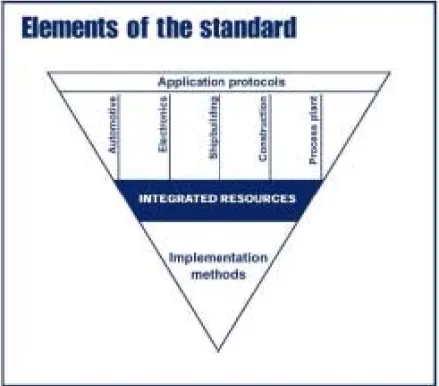
STEP is a family of standards under ISO-10303 for the exchange of product model data (UKCEB 2001). Parts 1, 11, 28, 221, 227 and 231 of the standard are discussed in this section. Part 1 explains the main concepts and gives an overview of the standard. Part 11 defines the EXPRESS description language used in the other parts. Part 28 specifies the way in which XML can be used to encode both EXPRESS schemas and the corresponding data. Part 221 is an Application Protocol (AP) for process plant functional data, part 227 is an AP for plant spatial configuration and part 231 is an AP for the exchange of process engineering data. Parts 1, 11 and 227 have already been published. Parts 28, 221 and 231 are still in a draft phase.
It has been stated that STEP is the principal product data exchange standard in the world (Burkett 1999). The design of STEP attempts to reconcile two objectives:
• Define a set of data elements that are unambiguous.
STEP defines integrated resources to meet the second of these objectives. The integrated resources are a collection of schemas written in the EXPRESS language. Integrated resources are designed to be applicable in all usage communities that deal with product data. As a result, the schemas are generic and flexible. The first objective is approached by introducing a technique called
interpretation. Interpretation explains how a generic integrated resource
construction, such as a product, is to be understood within a particular usage domain. Figure 2.2 illustrates the situation (Alemanni et al. 1999).
The formal language, EXPRESS, is specified for data and model formalisation. EXPRESS is independent of the language used for computer implementation. The language specifies generic concepts such as entity, attribute, type, rule and data types. A short example of the syntax of the EXPRESS language is given in Appendix A.
Figure 2.2. Different elements of the STEP standardisation (Alemanni et al. 1999).
Part 28 of the STEP standard belongs to the category of implementation methods
in the standard family. This draft specification is meant for XML-representation of EXPRESS-driven data. The specification defines two approaches for formulating document-type definitions (DTD) for information described by
using EXPRESS. The two approaches are called early binding and late binding. Late Bound DTD does not define any constructs that are specific to the schema. It can be used in the same manner for any EXPRESS schema. Early Bound DTD is based on the specific schema and embeds specific aspects, such as names or structures, from the schema in the DTD.
The two approaches can be related using architectural forms defined in
SGML/HyTime or ISO 10744. This is achieved by identifying the relationship between the two DTDs so that an application can recognise an element defined in one DTD as equivalent to an element in the meta-DTD and process the data according to the meta-DTD. EarlyBound DTD is compliant if it has LateBound
DTD as its base architecture (ISO 1999). The early and late bindings are of
interest also in this work and will be further discussed in Section 4.5. Interesting questions are for example, why late binding is needed and how an XML schema could be used for expressing architectural forms. Appendix A gives an example of both Late and Early Bound DTD and XML documents of the EXPRESS example introduced in the same Appendix.
STEP part 221 is concerned with the functional and physical aspects of plant items. The different aspects of a plant item relate to different activities, but both aspects are described by the same documents, e.g., P&IDs, data sheets and their electronic equivalents. The focus of part 221 (ISO 1997a) is:
• the piping and instrumentation diagram (P&ID), e.g. the arrangement of ink
on paper or pixels on a screen;
• the information that can be understood from a P&ID, e.g. the identification, classification and connectivity of plant items;
• and property information about the plant items. This can be accessed using
an intelligent P&ID system, but is traditionally presented on an equipment data sheet.
STEP part 227 specifies an application protocol for the exchange of the spatial configuration information of process plants, plant systems and ship systems. This information includes the shape, spatial arrangement and connection characteristics of piping, HVAC (heating, ventilation and air-conditioning) and cableway system components, as well as the shape and spatial arrangement
characteristics of other related plant systems (e.g., instrumentation and controls, and structural systems). (ISO 2001)
STEP part 231 defines an application protocol for the exchange of process engineering data. It specifies the process engineering and conceptual design information of process plants, including process designs, unit operations, process simulations, stream characteristics, and design requirements for major process equipment. The draft specification is rather extensive (more than 2500 pages) including about 40 categories of model items. Some central concepts related to process simulation are: (ISO 1998)
• Unit_operation specifies process functions that perform one or more defined
transformations on process stream(s) and whose performances are calculated as single logical entities.
• Stream_data specifies the process material, thermal or work energy, signals
or information flowing past a defined point along a path at a particular time. Streams usually flow into or out of a unit operation or through a port connection associated with process equipment.
• Process_port represents a flow of material, energy, or signal through the
boundary of a process simulation.
• Material_data specifies a physical material at its related stream conditions
that is used in or by a chemical process.
• Substance_model_data specifies the data associated with mathematical
model parameters that can be used to predict thermodynamic, physical, and transport properties of the substance.
Part 221 does not cover the spatial arrangements of plant items within a process plant. Data exchange for activities that involve both functional and spatial data may require the combined use of part 221 with part 227. On the other hand, part 221 does not cover the simulation of process activities either. Data exchanges for activities that involve both functional and process simulation data require the combined use of part 221 and part 231.
The Process Data Exchange Institute (pdXi) is a U.S.-based industrial consortium, organized as an industry technology alliance under the American Institute of Chemical Engineers (AIChE). pdXi was formed in 1991 with the stated purpose of developing open industry approaches for the electronic exchange of process engineering data. pdXi is the sponsor organization for the development of the application protocol 231. AP231 has been under development since 1995 and pdXi has actively participated in the work of the process plant working group developing AP231 and AP221. (Watts 1999)
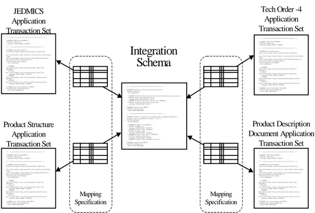
2.2.4 Product Data Markup Language (PDML)
Product Data Markup Language (PDML) is a set of XML vocabularies and a usage structure for deploying product data on the Internet. PDML is not a single data specification, but rather a structure of related specifications and tools to deploy and use integrated product data. It has been originally developed to be used by the weapon system support personnel of the U.S. Department of
Defence. PDML is composed of application transaction sets, an integration
schema, PDML toolkit and a mapping specification between the application
transaction sets and the integration schema. Figure 2.3 illustrates the relationship between these concepts. (Burkett 1999)
The application transaction sets are vocabularies meaningful within a well-defined community. The community is well-defined as the users of a particular legacy system, such as JEDMICS. JEDMICS is the primary system used by the U.S. Department of Defence for managing technical data. The application transaction sets overlap with respect to the data they include. The relationships between the data defined in these views are established through the mapping to the integration schema. The integration schema is an EXPRESS schema that serves as a neutral integration format for exchange of the transaction set data. The
schema is derived from the STEP integrated resource parts 41, 42, 43 and 44.
The relationship between each application transaction set and the integration schema is specified in the mapping specification. Mapping is more than a
conversion between data structures. It encompasses the interpretation of data
based on contextual values in the same way as interpretations are specified by mapping tables in STEP. (Shocklee et al. 1998)
<!-- =========================================== --> <!ELEMENT direction (direction.direction_ratios)> <!ATTLIST direction id ID #IMPLIED>
<!ELEMENT direction.direction_ratios (direction.direction_ratios.item+)> <!ATTLIST direction.direction_ratios aggregatetype CDATA #FIXED "LIST"> <!ELEMENT direction.direction_ratios.item (#PCDATA)> <!ATTLIST direction.direction_ratios.item datatype CDATA #FIXED "REAL"> <!ELEMENT direction_ref EMPTY> <!ATTLIST direction_ref refid IDREF #REQUIRED> <!-- =========================================== --> <!ELEMENT document (document.id, document.name, document.description, document.kind, (document_with_class?, file?)?)> <!ATTLIST document id ID #IMPLIED> <!ELEMENT document.id (#PCDATA)> <!ATTLIST document.id datatype CDATA #FIXED "STRING"> <!ELEMENT document.name (#PCDATA)> <!ATTLIST document.name datatype CDATA #FIXED "STRING"> <!ELEMENT document.description (#PCDATA)> <!ATTLIST document.description datatype CDATA #FIXED "STRING"> <!ELEMENT document.kind (document_type_ref)> <!ELEMENT document_ref EMPTY> <!ATTLIST document_ref refid IDREF #REQUIRED>
Integration
Schema
JEDMICS Application Transaction Set <!-- =========================================== --> <!ELEMENT identifier(#PCDATA)> <!ATTLIST identifier datatype CDATA #FIXED "STRING"> <!-- =========================================== --> <!ELEMENT part_relationship (part_relationship.other_relating_product_identifier, part_relationship.other_relating_.other_product_relationship _name, part_relationship.other_product_relationship_description, part_relationship.related_product)> <!ATTLIST part_relationship id ID #IMPLIED> <!ELEMENT part_relationship.other_relating_product_identifier (#PCDATA)> <!ATTLIST part_relationship.other_relating_product_identifier datatype CDATA #FIXED "STRING"> <!ELEMENTpart_relationship.other_relating_product_design_version (#PCDATA)>
<!ATTLIST
part_relationship.other_relating_product_design_version datatype CDATA #FIXED "STRING"> <!ELEMENT part_relationship_ref EMPTY> <!ATTLIST part_relationship_ref refid IDREF #REQUIRED>
Product Structure Application Transaction Set <!-- =========================================== --> <!ELEMENT identifier(#PCDATA)> <!ATTLIST identifier datatype CDATA #FIXED "STRING"> <!-- =========================================== --> <!ELEMENT part_relationship (part_relationship.other_relating_product_identifier, part_relationship.other_relating_.other_product_relationship _name, part_relationship.other_product_relationship_description, part_relationship.related_product)> <!ATTLIST part_relationship id ID #IMPLIED> <!ELEMENT part_relationship.other_relating_product_identifier (#PCDATA)> <!ATTLIST part_relationship.other_relating_product_identifier datatype CDATA #FIXED "STRING"> <!ELEMENT
part_relationship.other_relating_product_design_version (#PCDATA)>
<!ATTLIST
part_relationship.other_relating_product_design_version datatype CDATA #FIXED "STRING"> <!ELEMENT part_relationship_ref EMPTY> <!ATTLIST part_relationship_ref refid IDREF #REQUIRED>
Tech Order -4 Application Transaction Set <!-- =========================================== --> <!ELEMENT identifier(#PCDATA)> <!ATTLIST identifier datatype CDATA #FIXED "STRING"> <!-- =========================================== --> <!ELEMENT part_relationship (part_relationship.other_relating_product_identifier, part_relationship.other_relating_.other_product_relationship _name, part_relationship.other_product_relationship_description, part_relationship.related_product)> <!ATTLIST part_relationship id ID #IMPLIED> <!ELEMENT part_relationship.other_relating_product_identifier (#PCDATA)> <!ATTLIST part_relationship.other_relating_product_identifier datatype CDATA #FIXED "STRING"> <!ELEMENT
part_relationship.other_relating_product_design_version (#PCDATA)>
<!ATTLIST
part_relationship.other_relating_product_design_version datatype CDATA #FIXED "STRING"> <!ELEMENT part_relationship_ref EMPTY> <!ATTLIST part_relationship_ref refid IDREF #REQUIRED>
Product Description Document Application Transaction Set <!-- =========================================== --> <!ELEMENT identifier(#PCDATA)> <!ATTLIST identifier datatype CDATA #FIXED "STRING"> <!-- =========================================== --> <!ELEMENT part_relationship (part_relationship.other_relating_product_identifier, part_relationship.other_relating_.other_product_relationship _name, part_relationship.other_product_relationship_description, part_relationship.related_product)> <!ATTLIST part_relationship id ID #IMPLIED> <!ELEMENT part_relationship.other_relating_product_identifier (#PCDATA)> <!ATTLIST part_relationship.other_relating_product_identifier datatype CDATA #FIXED "STRING"> <!ELEMENT
part_relationship.other_relating_product_design_version (#PCDATA)>
<!ATTLIST
part_relationship.other_relating_product_design_version datatype CDATA #FIXED "STRING"> <!ELEMENT part_relationship_ref EMPTY> <!ATTLIST part_relationship_ref refid IDREF #REQUIRED> Mapping
Specification
Mapping Specification
Figure 2.3. Relationship of PDML components (Burkett 1999).
The integration performed in the toolkit is driven by the mapping specifications. Using the mapping specification, the toolkit can convert data encoded according to an application transaction set to the format specified by the integration schema. This integrated data set can then be converted back out to data conforming to another application transaction set (Burkett 1999). The application transaction sets, the integration schema and mapping specification and their relationship to the approaches chosen in this work are discussed in Section 4.5.
2.2.5 OLE for Process Control (OPC)
The OPC Specification is a non-proprietary technical specification that defines a set of standard interfaces based upon the OLE/COM specifications by Microsoft (Microsoft 1995). The application of the OPC standard interface makes the
interoperability between automation/control applications, field systems/devices
OPC consists of several sub-specifications and the OPC foundation has currently many working groups developing new parts to the specification. The most interesting specifications related to this work are Data Access 2.0 (DA), Data Exchange (DX), OPC XML, OPC Commands and OPC Security. So far, only the DA specification has been published. Other specifications are in a draft phase. The Alarms and Events (AE), Batch and Historical Data Access (HDA) specifications are not discussed in this work.
OPC DA servers can be implemented as ‘in process’ or ‘out process’ servers. An
in process server is a dynamic link library (dll) that runs in the same process as
the client application. The components implemented in EXE files are out
process servers. An out process server can be local or remote according to the
location of the server with respect to the client process. The underlying
communication is implemented using a proxy and stub mechanism. The proxy
marshals data passed to the interface functions and makes a local or remote procedure call to the server. The stub un-marshalls parameters and calls the correct interface function in the component.
The data model of the OPC DA consists of server, group and item objects. Server and group objects consist of several interfaces. The client can add and delete group objects, handle error codes and access server status data through the
interfaces of the server object. The client can also browse the server address
space, save and load server configurations and handle public groups. However, the latter functionality is only available if the interfaces, marked as optional in the specification, are supported. The server object is a container for group
objects. Group objects are defined and maintained by the client. Through a
group object, the user can add and delete items, activate and deactivate groups
and items and access data values using synchronous or asynchronous communication. The application and use of DA interfaces in the developed architecture is discussed in sections 4.7 and 5.3.
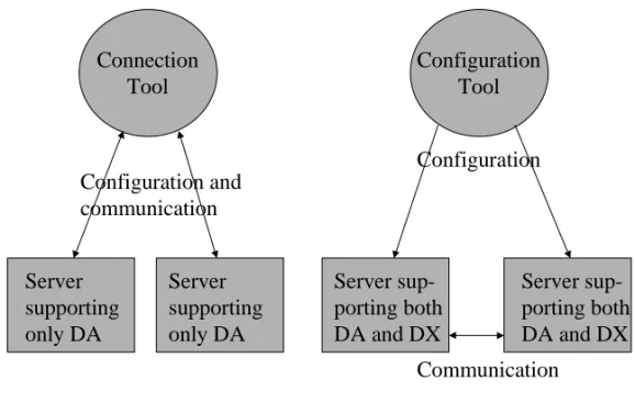
OPC DA has mainly been used for vertical data exchange between control
application or field devices and office applications. A connecting client
application is needed for horizontal data exchange between the control
applications (see Figure 2.4). This causes extra overhead in the communication. Because the data goes through the client process, additional copy operations and function calls have to be performed. The OPC Data Exchange initiative has been
put forward to avoid this extra overhead and to avoid the extra implementation of client configuration features into every OPC server. DX specification uses DA for the communication and specifies extra interfaces for the configuration of the DA communication between servers. The connection list object defines the communication between two OPC DA servers. The connection list object consists of connection group objects and connection group object consists of connection objects. Connection group and connection objects correspond to the group and item object in the DA specification.
Figure 2.4. Difference between horizontal and vertical data exchange between OPC servers.
The goal for the OPC XML initiative is to develop flexible, consistent rules and formats for exposing plant floor data using XML. The focus is to expose the same data as the existing OPC interfaces expose. Another objective is to leverage the work done on Biztalk, SOAP and other XML frameworks. This will lead to easier web access, for example.
The OPC command specification will be a part of Data Access 3.0. According to the working group, a command is an action that takes a long time to execute and
Server supporting only DA Server supporting only DA Server sup-porting both DA and DX Server sup-porting both DA and DX
Before DX specification After DX specification
Connection Tool Configuration Tool Configuration and communication Configuration Communication
that changes the state of the server or the data source. The idea is to add two new interfaces to the OPC DA server object. One is meant for retrieving information on the commands that the server supports and the other one is meant for executing those commands. The command information could be for example
name and description information. The command execution is asynchronous and
the command syntax, as well as the command information, is expressed in XML.
The OPC security specification specifies three different levels of security for an OPC server. On the disabled security level, launch and access permissions to the OPC server are given to everyone, and access permissions for clients are set for everyone. On the DCOM security level, launch and access permissions to the OPC server are limited to selected clients as are access permissions for the client applications. However, the OPC server does not control access to any vendor-specific security objects. On the OPC security level, the server controls the access to vendor specific security objects. On this level, the server can also support DCOM security.
2.3 Current Process simulation systems
2.3.1 Introduction
The state of the art of the current process simulation systems is analysed in this section. First, the process simulation tools are grouped according to the common features in their simulation approaches. Then, some of the tools are analysed in more detail by posing the same set of questions for each tool. The questions concentrate on the important properties for the requirements represented in this work. A short overview of each simulator is also given.
The number of commercial simulation tools is large. The technology review of the National Technology Agency, TEKES, on process modelling and simulation lists 16 different modelling and simulation tools in Finland only (Klemola & Turunen 2001). In the Netherlands, the Agency for Energy and Environment lists 91 different software tools for process integration, most of them including simulation capabilities (Novem 2000). It would be quite impossible to cover all of these tools. The selection of the studied tools is made according to the topics
represented in Section 2.1 and according to the availability of the tools for testing.
There are many steady state process simulation tools that could benefit from a
link to common software architecture. Many of these tools focus on a specific
application domain, on specific unit operations or on a specific phase in the process design life cycle. Several focused tools have also been developed in Finnish universities and companies (Klemola & Turunen 2001). Typically, the input topology and parameter values are first read from a file, then the steady state for the process is calculated and, at the end, the output is written to a file. Graphical user interfaces are used to produce the input file and to represent the results graphically to the user (Prosim 2000; Balas 1998). Many of the simulators are implemented as monolith applications having a poor extensibility.
Some of the process simulators have a modelling language of their own. For
example, process simulators built on top of Extend (Extend 2001) platforms, such as Ideas (Ideas 2001) or Flowmac (Flowmac 2001) use the ModL modelling language of the Extend platform. Another example is EL, which is the modelling language used in the EcosimPro platform (Ecosim 2001). In fact, this is one feature that can be used to characterise a simulation tool. Either it uses a modelling language of its own or it uses some general programming language, for example Fortran, C++ or Java.
A process simulation system often has at least two different user groups. The first group develops new models for different unit operations by programming new solution algorithms to the system. The users of the second group are often process engineers configuring the process models using the developed unit operation models. Generalised simulation systems often focus more on developing tools for the first user group. This is natural because the system may be used by a variety of model developers from different application domains, so the tools must be general. However, one can argue whether the result is the best possible for the end user. The generality of the simulator can be used as another feature to characterise a simulation tool. At one end we have very generic tools such as Matlab (Matlab 2002) or Modelica (Elmqvist et al. 1999) and at the other end we have very specialised tools for process simulation such as Hysys (Hysys 2000), CADSIM Plus (CadsimPlus 2001) or Apros/Apms (Apros 1999).