High Availability Design Patterns
Kanwardeep Singh Ahluwalia
81-A, Punjabi Bagh,
Patiala 147001
India
+
91 98110 16337
[email protected]
Atul Jain
135, Rishabh Vihar
Delhi 110092
India
+91 98119 84678
[email protected]
ABSTRACT
As information technology spreads its wings in to all spheres of human life, including areas which are mission-critical, like telecom services, medical sciences, air transport systems, space missions etc., High Availability (HA) has become utmost important aspect in the development of these systems. This paper presents a pattern language that can be used to make a system highly available.
Categories and Subject Descriptors
C.4 [Performance of Systems]: Performance attributes, Reliability, availability, and serviceability.
General Terms
Algorithms, Performance, Design, Reliability.
Keywords
High Availability, Availability, Monitor, Reliability, Downtime, Fault, Detection, Recovery, Tolerance, Redundancy, Active-Passive, Standby, Throughput, Replica, Failure, Notification.
1.
INTRODUCTION
In information technology, high availability refers to a system or component that is continuously operational for a desirably long length of time. Availability can be measured relative to "100% operational" or "never failing."
In actual practice, availability goals are expressed and measured in the number of nines of availability ranging typically from 99.9% (3NINES) to 99.999% (5NINES) and even up to 99.9999% (6NINES) availability for the most demanding applications.
Mission critical applications like those found in telecommunications need to meet and exceed 5NINES. Table 1 shows the annual downtime and typical availability for various classes of system applications.
Table 1 High Availability Standards
Typical Application Availability (%) Down Time per Year
Typical Desktop or Server Enterprise
Server Carrier-Grade Server Carrier Switch Goal
99.9 (3NINES) 99.99 (4NINES) 99.999 (5NINES) ~9 hours ~1 hour ~5 minutes The patterns in this paper address the architectural and design choices that one must consider when designing a highly available system. These patterns are not discussing the programming techniques that can be used to implement these patterns. The intended audience includes system architects and designers who are designing reliable systems.
The pattern “System monitor” presented in this paper duplicates pattern form “Detection Patterns for Fault Tolerance” by Robert S. Hanmer – PLoP 2004. This pattern has been presented here to take its place in the larger collection of patterns presented here for High Availability.
The term ‘part of a system’ will be used here to denote an element of a system that could be a software or hardware component used in the system.
The term ‘client to the part’ will be used here to denote any entity that is communicating with a part of the system. It may not necessarily mean the ‘end client’ of the system. It can be some other part of the system as well who is interacting with other parts of the system.
The following definitions [1] of terms fault, error and failure shall help to understand the patterns described in this paper.
• a system failure occurs when the delivered service deviates from what the system is intended to do (e.g. as stated in its specification).
• an error is that part of the system state which is liable to lead to subsequent failure.
• a fault is the (hypothesized) cause of an error.
2.
LANGUAGE MAP
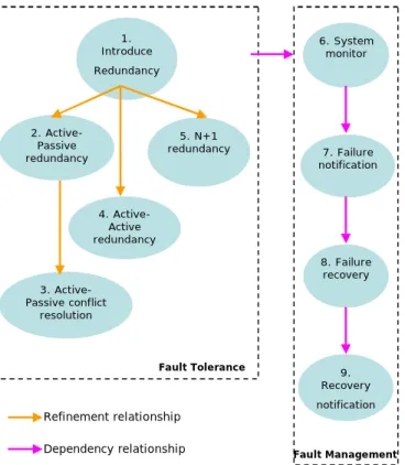
Figure 1 shows how various patterns work together to make a system highly available.
The patterns analyzed in this paper fall in two groups. Patterns 1 to 5 fall in the group “Fault tolerance” as these patterns suggest various options by which a part of the system can be made fault tolerant by making it redundant. Patterns 6 to 9 fall in the group “Fault management” as these patterns suggest Permission to make digital or hard copies of all or part of this work for
personal or classroom use is granted without fee provided that copies are not made or distributed for profit or commercial advantage and that copies bear this notice and the full citation on the first page. To copy otherwise, to republish, to post on servers or to redistribute to lists, requires prior specific permission and/or a fee.
PLoP '06, October 21–23, 2006, Portland, OR, USA. Copyright 2006 ACM 978-1-60558-151-4/06/10…$5.00.
how failures can be detected and notified so that recovery can be done and system be notified about recovered parts so as to gain redundancy in the system.
Figure 1 High Availability Pattern Language
3.
PATTERNS DESCRIPTION
3.1
Pattern 1: Introduce Redundancy
3.1.1
Context
System that wants to continue working normally under conditions when one of its parts fails.
3.1.2
Problem
What should a system do to continue working normally even if one of its parts fails?
3.1.3
Forces
• The cost of keeping the system working even in case a part of it fails should be low.
• The client’s requests should be processed transparently even if there is failure in the system.
3.1.4
Solution
The key to a reliable design is to identify and address single points of failure. Single points of failure are those parts whose failure causes the entire system to fail. A production server is a complex system and many factors affect its availability, including environment, communication links, software, and hardware. Each of these factors can potentially be the source of a single point of failure.
Redundancy is a means to address single points of failure. It is achieved by replicating a single part of the system which is critical for system functioning. The replication will make sure that if the critical part fails, there would be an alternate part available to take on the responsibility of the failed part. Redundancy is based on the assumption that multiple faults will not occur in the system together.
Redundancy can be in the form of hardware redundancy or software redundancy. Hardware redundancy aims at having replicated set of hardware while software redundancy aims at having multiple instances of the software, all aiming to achieve same results but with different ways of implementation.
The replicated part may be introduced in a stand-by form also known as active-passive redundancy, or it may be introduced in active-active form where in all replicas are active at the same time. If one replica "throws a fault", then other replicas can be used immediately to allow the system to continue operating normally.
3.1.5
Resulting Context
System would be able to function even if a critical part fails. Introduction of redundancy shall make sure that there is no single point of failure in the system. If a critical part fails, its functionality shall be served by someone else. This shall make the system always up and running and hence serve the client requests without any failures.
3.1.6
Structure
Figure 2 shows that the single point of failure in the system has been made redundant by having one or more replicas as demanded by the situation. This helps in making the system highly available since ‘single point of failure’ no more exists.
Figure 2 Redundancy Structure
3.1.7
Known Uses
Almost all the team games (cricket, hockey etc.) have two sets of players. One set of players are active which are playing in the field while other set of team is used as ‘extras’ which become active, when some of active members are not able to play (due to injury or rules of the game).
The avionics are designed to withstand multiple failures through redundant hardware and software. Example of hardware redundancy can be found in an airplane which has multiple flight computers to provide high availability. Similarly example of software redundancy can be found in the navigation systems, where the back up system consists of a different implementation, so that if the primary software implementation fails (let’s say due
Replica 1 Replica 2 Replica N After Failure 2. Active-Passive redundancy 4. Active-Active redundancy 5. N+1 redundancy 1. Introduce Redundancy 6. System monitor 9. Recovery notification 8. Failure recovery 7. Failure notification 3. Active-Passive conflict resolution Fault Tolerance Refinement relationship
to an operand error), the probability of the failure of the back up system for the same data is low.
Another commonly known example of redundancy is redundant arrays of inexpensive disks (RAID), which employs two or more drives in combination.
3.1.8
Related Patterns
Active-Passive redundancy [3] Active-Active redundancy [4] N+1 redundancy [5]3.2
Pattern 2: Active-Passive redundancy
3.2.1
Context
You have determined that you need to Introduce Redundancy [2] into your system, that has neither dearth of resources to provide redundancy nor can compromise on performance.
3.2.2
Problem
What should the system do to function without any compromise on its performance even if one of its parts fails?
3.2.3
Forces
• Performance should not be compromised.
• Failed part’s client should be able to get its requests processed seamlessly.
• System should not loose its state (in case of stateful systems), due to failure of its part.
3.2.4
Solution
Introduce active-passive redundancy for the critical part of the system which may potentially act as a single point of failure in the system. This critical part of the system is provided with a standby replica which shall be activated in case of failure of the former.
The client to the failed part should be informed about the passive part’s activation by fault management sub system (a system implementing ‘Fault management’ related patterns shown in the Figure 1), so that it can get its request served by the new activated part and does not try to send the requests to the failed part. The client should provide handling for failure notification from the fault management sub-system so that it can re-direct requests to the newly activated part.
In case the part has some state which system can not afford to loose in case of its failure, the state also needs to be replicated in the standby part. Thus helps the system to maintain its data (state) integrity in case of failures. All the state changes in the active part should be sent over to the passive part. There is a need for a good communication channel between active-standby, so that state updates are sent over the communication channel in real-time.
3.2.5
Resulting Context
The introduction of a standby part makes sure that the performance and throughput of the system is not impacted in case of failure of active part. Thus, each active part is replaced by its replica upon its failure, keeping the system’s capability same as before the occurrence of failure. Here, it is assumed that the standby part has the same capabilities as of active part. Otherwise, the performance of the system may vary depending up on the capabilities of the passive part.
The handling of failure notifications in the client to the failed part makes sure that there is a seamless switch over happening to the newly activated part and no requests are failing because of failure of previously activated part.
The continuous update of state by active to passive part makes sure that the state possessed by the failed part is not lost.
3.2.6
Structure
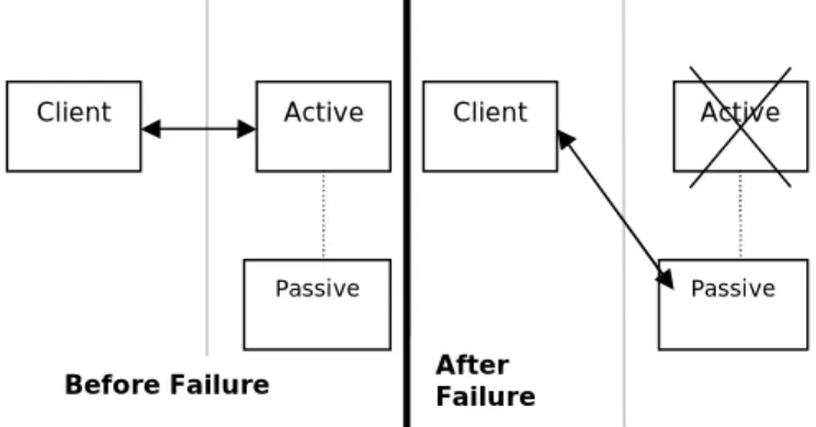
Figure 3 shows that the single point of failure has been removed by providing a replica of the same. This replica is not participating in serving the client requests. The requests are only processed by the active part. However, as soon as active part fails, the passive part takes over the control and starts processing the requests. Hence, at any given moment, there is only one part which is serving the requests.
Figure 3 Active Passive Redundancy Structure
3.2.7
Known Uses
Many mission critical establishments are provided with an emergency power generator which becomes active as soon as the primary power source fails.
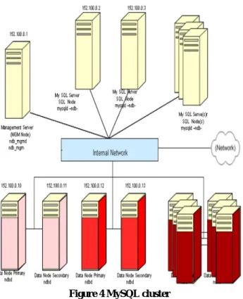
Another known use can be found in MySQL database cluster solution [3]. All potential single points of failure are made redundant in this solution. This includes data nodes, network cards, switches and links.
The data nodes are made redundant with a standby node acting as mated pair. There is active communication going on between these two active and passive nodes, so that state is also replicated between these pairs. Thus, MySQL suggests having efficient network connectivity between these mated pairs of active-standby data nodes. As soon as active data node goes down, SQL node is made aware of the failure and it connects to the passive data node. Figure 4 depicts the clustered architecture of MySQL. Active Passive Client Active Passive Client After Failure Before Failure
Figure 4 MySQL cluster
The node pairs 152.100.0.10 - 152.100.0.11 and 152.100.0.12 - 152.100.0.13 are mated data nodes out of which one acts as active (primary) and the other as passive (secondary).
3.2.8
Related Patterns
Introduce Redundancy [2]
Active-Passive conflict resolution [4]
3.3
Pattern 3: Active-Passive conflict
resolution
3.3.1
Context
System that needs to implement Active-Passive redundancy [3] for high availability.
3.3.2
Problem
What should the system do in case both the redundant parts in Active-Passive redundancy claim to be active?
3.3.3
Forces
• There should not be deadlock between the redundant parts to become active.
3.3.4
Solution
Introduce a mechanism so that there is no conflict between the redundant parts to become active and at any given point of time there is only one active part. However, there can be situation which may lead to race conditions, where in both the redundant parts claim to be active. There are various mechanisms to resolve this conflict.
To resolve the conflict in redundant hardware, one of the solutions can be that the hardware with smaller id shall become active at start-up.
Alternatively, the redundant parts shall generate a random number and the one who generates a number with lower value shall become active and the other becomes passive.
Another solution is that the redundant parts exchange their startup time stamp and see which one of them came up (started) first. The one with older time stamp can be considered as the active and other one will play the role of passive part.
3.3.5
Resulting Context
The introduction of conflict resolution algorithm depending up on the scenario shall reduce the possibility of conflicts while deciding who shall become active out of the redundant parts.
3.3.6
Structure
Figure 5 shows that the replicas need to follow an algorithm to have a handshake on who will become active.
Figure 5 Active Passive Conflict Resolution Structure
3.3.7
Known Uses
In a switching system, whenever a redundant pair of controller cards come up after initialization during system start up, each can claim to be a master due to race conditions. They use hardware ids to resolve the conflict.
3.3.8
Related Patterns
Active Passive Redundancy [3]3.4
Pattern 4: Active-Active redundancy
3.4.1
Context
You have determined that you need to Introduce Redundancy [2] into your system and want to keep the cost low by not investing in passive redundant resources and homogenous software configuration.
3.4.2
Problem
What should the system do if it has limited resources to provide redundancy but still wants to be functional in case of failure of a critical part?
3.4.3
Forces
• The system should maximize the usage of its resources.
• The client (to redundant) part should be talking to a single entity and get its requests processed seamlessly.
• The state (in case of a stateful part) should not be lost in case of failure of a part.
3.4.4
Solution
Introduce active-active redundancy for the critical part. In this case, redundancy is introduced by having more than one active part. All the redundant parts are active and helping in processing at the same time. This solution is sometimes known as cluster, which is a collection of resources that functions as a single computing resource. Any member of the cluster can
Replica 1
Replica 2
Conflict resolving Algorithm
service a client request without the client knowing which member performed the operation. This is made possible by introducing another entity between the client and the cluster members, usually known as dispatcher [4]. The client talks to the dispatcher which further get the requests processed by cluster members. Using dispatcher, the cluster can be configured so that an application fails over from one cluster member to another. This is usually only possible when cluster members utilize a homogenous software configuration. The dispatcher keeps the information about all the failed members as well as working members, which helps in forwarding requests only to active members.
The number of redundant parts required is calculated depending up on the peak load requirements on the system. One additional part is added to the number of redundant parts required to handle the peak load so as to have same efficiency even if a part fails.
In case cluster members are keeping some state which they can not afford to loose in case of failure, the state also needs to be replicated in all other members. This helps the system to maintain its integrity in case of failures. However, as the size of cluster grows, the cost to replicate the state increases, as state updates are being sent across all the cluster members. There is a need for a good communication channel between cluster members, so that state updates are sent by active to passive over that communication channel in real-time.
3.4.5
Resulting Context
By introducing a redundant part which is also active, overall cost has been saved, since the replica is also helping in processing.
The introduction of dispatcher makes sure that the client is not bothered about the status of each of the cluster members.
3.4.6
Structure
Figure 6 show that both all the replicas are actively processing the client requests.
Figure 6 Active Active Redundancy Structure
3.4.7
Known Uses
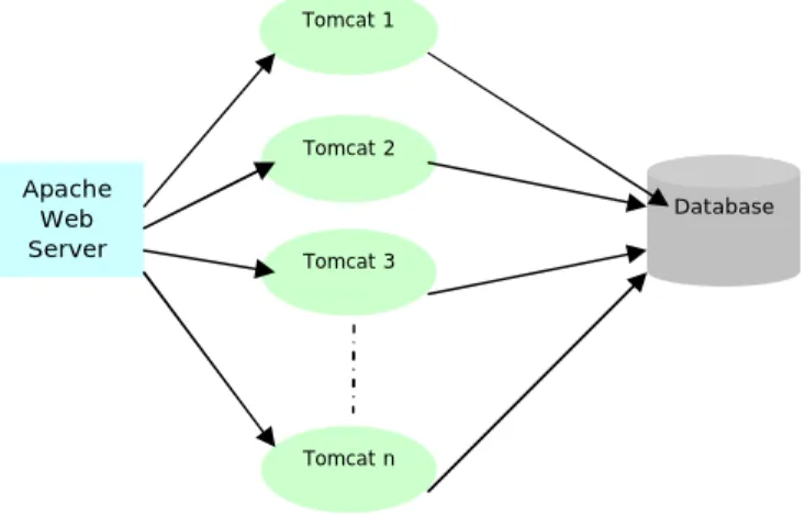
One of the known examples of active-active redundancy is Apache’s Tomcat cluster solution for web based applications. As shown in Figure 7, an Apache web (HTTP) server acts as a communication point for all the web clients. Apache web server would be further connected to various Tomcat instances through mod_jk [2] module.
Figure 7 Apache Tomcat Cluster
In case any Tomcat sever fails, Apache web server stops sending requests to that instance. The clients who were being served by the failed instance shall now be served by some other Tomcat instance.
Tomcats can also be configured to replicate their state among themselves, so that if any of the Tomcat server crashes, its state is not lost.
3.4.8
Related Patterns
Introduce Redundancy [2]3.5
Pattern 5: N+1 redundancy
3.5.1
Context
You have determined that you need to Introduce Redundancy [2] into your system that consists of parts with heterogeneous software configuration and does not want to waste resources by providing one passive node for each potential single point of failure.
3.5.2
Problem
What should the system do if it does not want to waste resources by having a standby part for each active part, but still wants to behave normally in case of limited failure?
3.5.3
Forces
• The cost and resources required for introducing Active-Passive Redundancy[3] should be reduced.
• The system should be able to handle failure in one out of N parts without any compromise on performance.
• The client should be talking to a single entity and get its requests processed seamlessly.
3.5.4
Solution
Introduce 1 slave (passive) for N potential single point of failures in the system. This slave would be working in a standby mode and waiting for a failure to happen in any of the N active parts. As soon as any of the N active parts fails, then the standby part takes over the work of the failed one. This way the system shall be able to handle one failure for every N critical active parts at any given point of time. The number ‘N’ can motivated by various factors, like the expected number of failures that can happen at any given point of time in a group of active parts and the cost and resources required while introducing the redundant parts. Apache Web Server Tomcat 1 Tomcat 2 Tomcat 3 Tomcat n Database Active Replica 1 Active Replica 2 Client
The client should provide handling for failure notification from the fault management sub-system so that it can re-direct requests to the newly activated part. This shall make sure that the requests are getting processed seamlessly.
3.5.5
Resulting Context
The introduction of 1 standby part for every N active parts makes sure that the system is able to handle failure of one out of N active parts. Since, only N parts are being introduced to a single standby part, the cost of introducing redundancy is reduced as compared to 1:1 active-passive redundancy.
3.5.6
Structure
Figure 8 shows that there is one passive part for N potential single point of failures in the system. If any of these N parts fails, then the passive part shall takeover the functionality of the failed part.
Figure 8 N+1 Redundancy Structure
3.5.7
Known Uses
Modern communications systems with multi-port T1/E1/J1 line cards employ redundancy to achieve the high-availability that telecom networks require. Usually, these systems use relays to implement N+1 redundancy switching.
3.5.8
Related Patterns
Introduce Redundancy [2]3.6
Pattern 6: System Monitor
3.6.1
Context
You have determined that you need to Introduce Redundancy [2] into your system that wants to monitor failures of its parts to avoid potential single point of failures which may lead to non-functioning of the system.
3.6.2
Problem
How to detect that the failure has occurred in the system?
3.6.3
Forces
• Failure must be detected at the earliest instance so that the faulty part does not corrupt the behavior of the system.
• Failure must be detected at the earliest so that faulty part can be recovered; before any additional failures in the system makes the system completely non functional.
3.6.4
Solution
Introduce a mechanism to monitor all potential single point of failures in the system, so that upon failure, the fault tolerance mechanism can be activated. This pattern can be refined as depicted in the Figure 9 which has been taken from the work of Robert Hanmer [5].
Figure 9 Monitoring Failures
The SYSTEM MONITOR [5] can employ any of the following solutions.
The system can rely on ACKNOWLEDGEMENT [5] messages exchanged with monitored part, or it can rely on I AM ALIVE [5] messages sent by the monitored part. Alternatively, the system can periodically check the state of the monitored part by sending ARE YOU ALIVE [5] messages. The system can SET A REALISTIC THRESHOLD [5] after expiry of which it may consider the monitored part to be dead.
Each of the above solutions adds complexity to the system. To minimize complexity, system monitor can just watch and verify the tasks performed by the monitored part using WATCH DOG [5] mechanism.
A brief description of each pattern is given below:
SYSTEM MONITOR: This pattern recommends creating a task to monitor system behavior, or the behavior of specific other tasks, i.e. make sure that they continue operating.
ACKNOWLEDGEMENT: This pattern recommends inclusion of an acknowledgement requirement on all requests. All requests should require a reply to acknowledge receipt and to indicate that the monitored system is alive and able to adhere to the protocol. If the acknowledgement reply is not received then report a failure.
I AM ALIVE: This pattern recommends that the monitored system should send a report to the SYSTEM MONITOR at regular intervals. If the monitoring system fails to receive these reports it should report that the monitored task has stopped.
ARE YOU ALIVE: This pattern recommends that the SYSTEM MONITOR should send periodic requests for status to the monitored task. If the monitored task doesn’t reply within the required time then action to recover it should be taken.
SET A REALISTIC THRESHOLD: This pattern recommends maximizing the latencies so that the SYSTEM MONITOR will be informed in a timely enough manner to meet the availability requirement.
Potential SPoF 1 Potential SPoF 2 Potential SPoF N Passive Replica For 1,2,.., N Client Potential SPoF N+1 Potential SPoF N+2 Potential SPoF N+N Passive Replica For N+1 To N+N
WATCH DOG: This pattern recommends adding in the capability for the monitor to observe the monitored tasks activities, much as a Watchdog tends the flock. This Watchdog can be either hardware or a software component depending on the system requirements, but in either case it will watch visible effects of the monitored task. The monitored task will not be modified.
3.6.5
Resulting Context
Implementation of ACKNOWLEDGEMENT, I AM ALIVE, ARE YOU ALIVE, SET A REALISTIC THRESHOLD and WATCHDOG helps in detecting the failures at the earliest, which helps the system to avoid a situation where it is not behaving as per the specifications and further leading to its non-functioning.
3.6.6
Structure
Figure 10 shows that all the replicas (monitored parts) are being observed for any failures by System monitor.
Figure 10 System Monitor Structure
3.6.7
Known Uses
In case of Tomcat cluster solution, Apache HTTP server keeps on checking the health of various Tomcat servers using its mod_jk [2] module.
In case of real time systems based on non-preemptive priority process scheduling, each process is expected to utilize the CPU for a definite amount of time and voluntarily relinquish the CPU before the expiry of the definite amount of time. If due to a fault, any process misbehaves and starts to hog the CPU, the watch dog process that is monitoring all the processes, detects the process failure on controller card and triggers the fault tolerance mechanism.
3.6.8
Related Patterns
Introduce Redundancy [2]3.7
Pattern 7
Failure Notification
3.7.1
Context
You have implemented System Monitor [6] in the System that now wants to handle failures of its parts to avoid potential single point of failures which may lead to non-functioning of the system.
3.7.2
Problem
What should system do when it detects a failure in a part?
3.7.3
Forces
• Failed part should not be given any requests for processing to avoid mal-functioning of the system.
• System should initiate the handover of responsibilities of the failed part to a redundant part.
• System should initiate recovery of failed part.
3.7.4
Solution
The SYSTEM MONITOR should notify the fault recovery sub-system so that the failed part can be immediately isolated by marking it out of service, thereby restricting the failed part from impacting the behavior of the system.
Since the system is expected to finish the requested task despite failure, it must notify the fault tolerance sub-system so that the redundant part takes over the functions of the failed part immediately.
Systems often may not afford to provide redundancy at all levels in the system hierarchy. In such situations, if the failure occurs at a level where redundancy is not available, the failure notification should be propagated up to a level where client to redundant sub-system is available. This will enable client to switch over to the redundant sub-system so as to get its requests processed seamlessly.
There may be situations, where the failed part of the system may not be recovered by the fault recovery sub system without manual intervention. In such situations, it is recommended to notify the I/O [6] system to generate audio or visual alarms depending upon the criticality of the failure.
3.7.5
Resulting Context
The notification of the recovery sub-system initiates isolation and recovery of the faulty part which helps the system to function flawlessly.
The notification to the fault tolerance sub-system triggers an appropriate action to activate the redundant part.
3.7.6
Structure
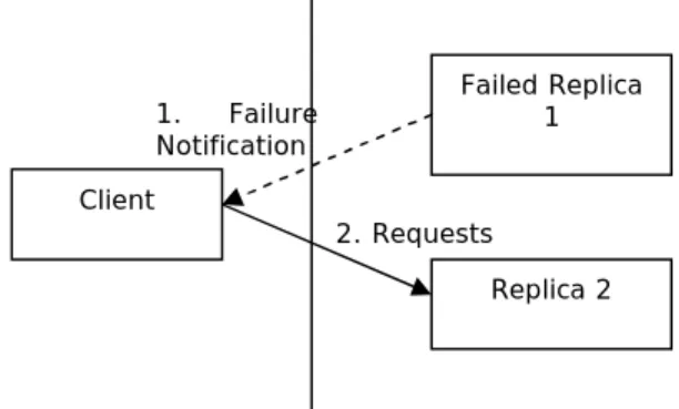
Figure 11 shows that the client is being notified up on failure of a replica, so that client no more gives requests to the failed part. The steps have been explained below.
Step 1: Failed replica 1 notifies the client about its failure. Step 2: The client stops sending requests to the failed replica 1 and uses replica 2 which helps in processing the requests without failure.
Figure 11 Failure Notification Structure
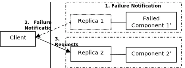
Figure 12 shows that the client is being notified up on a failure at a level where redundancy is not available. The steps in the diagram have been explained below.
Step 1: Failed component 1’ notifies about its failure to replica 1.
Step 2: Since, there is no redundancy related to component 1’, replica 1 has to further inform the client about the failure of
Failed Replica 1 Replica 2 Client 1. Failure Notification 2. Requests Monitored part 1 System Monitor Monitored part 2 Monitored part 3
its chain. So in this step, replica 1 notifies the failure of component 1’ to the client.
Step 3: The client after receiving failure notification from replica 1 stops sending requests to replica 1 chain (even though replica 1 is working) and starts sending requests to replica 2.
Figure 12 Failure Notification Structure for multi level components
3.7.7
Known Uses
In a switching system, the moment one copy of the controller card fails or is marked out of service, it toggles the control signal on its control bus which sends the hardware signal to the redundant copy to take over.
3.7.8
Related Patterns
System Monitor [6]3.8
Pattern 8: Failure Recovery
3.8.1
Context
You have implemented Failure Notification [7] in the System that now wants to recover its failed part.
3.8.2
Problem
How to recover the failed part of the system?
3.8.3
Forces
• Recovery mechanism should be capable of isolating the fault.
• Recovery mechanism should be capable of handling faults that require manual intervention.
3.8.4
Solution
The failed part tries to self recover by re-initializing itself. If the re-initialization fails, the part is sent for manual recovery using various alarming techniques like Audible Alarms, Alarm Grid and Office Alarms [6]. Manual recovery involves isolation and resolution of the fault.
3.8.5
Resulting Context
The faulty part has been recovered by isolating the fault using diagnostics and fixing the same using manual procedures.
3.8.6
Structure
The following diagram shows how the failed replica is being recovered from the fault.
Figure 13 Failure Recovery Structure
The steps in Figure 13 have been described below.
Step 1: The failed replica tries to re-initialize itself in order to overcome the failure due to transient fault.
Step 2: If the re-initialization is not successful, alarm is raised to invite manual intervention for diagnosis of the fault and its resolution.
3.8.7
Known Uses
In a switching system, whenever a controller card is sent for recovery, the fault recovery subsystem tries to re-initialize the data as well as the binary code on the card to recover from any data or binary corruption faults. In case the problem still persists after the re-initialization, the card is sent for diagnostics in order to isolate the hardware faults. Based on the diagnostics test results, the operator takes appropriate actions to fix the fault, e.g., replacing the controller card with a new card.
Whenever humans fall ill (may be fever), they first try to recover by taking commonly available medicines. However, if they still do not recover, then doctor’s help is sought, who would suggest some diagnostic tests to be done to identify the root cause of the problem and treat the same.
3.8.8
Related Patterns
Failure Notification [7]3.9
Pattern 9: Recovery Notification
3.9.1
Context
You have implemented Failure Recovery [8] in the System.
3.9.2
Problem
What should system do after the faulty part has recovered?
3.9.3
Forces
• The system should reinstate the recovered part to have redundancy in the system.
• The recovered part should be put in to use ‘immediately’ to make the system resilient about future failures.
3.9.4
Solution
Fault tolerance subsystem should be notified about the recovery of the failed part as soon as it recovers, so that the recovered part can be reinstated to provide redundancy in the system.
In case of stateful systems, the recovered part should start synchronization with its peer nodes, in order to prepare itself for processing the requests.
3.9.5
Resulting Context
The notification to fault tolerance sub-system results in the inclusion of recovered part in the system which provides redundancy in the system.
Failed Replica Manual recovery Re-initialization (Self recovery) 1 Recovered Replica 2 3 Replica 2 Client 2. Failure Notificatio 3. Requests Replica 1 Failed Component 1’ Component 2’ 1. Failure Notification
3.9.6
Structure
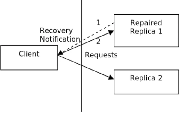
The following diagram shows that the client starts sending requests to the repaired part after it is informed about its recovery.
Figure 14 Recovery Notification Structure
The steps in Figure 14 have been explained below.
Step1: The client is notified about the recovery of the failed replica 1.
Step2: The client starts sending requests to rreplica1, hence reinstates the recovered part. This makes the system highly available.
3.9.7
Known Uses
In case of MySQL cluster solution, whenever one of the redundant data nodes comes up after recovery, it notifies the
management server about its recovery and makes the data nodes redundant.
3.9.8
Related Patterns
Failure Recovery [8]4.
ACKNOWLEDGMENTS
We would like to thank Kyle Brown for his feedback and encouragement during shepherding of these patterns.
Credit also goes to the participants of writer’s workshop at PLoP’06 who gave very useful comments.
5.
REFERENCES
[1] Deepal Jayasinghe. Fault Tolerance with FAWS.
http://www.jaxmag.com/itr/online_artikel/psecom,id,733,no deid,147.html
[2] Gal Shachor. Working with mod_jk. Available at
http://tomcat.apache.org/tomcat-3.3-doc/mod_jk-howto.html [3] MySQL Cluster documentation available at
http://dev.mysql.com/doc/refman/5.1/en/ndbcluster.html [4] P. Sommerlad and M. Stal. 1995. PLoP. The
Client-Dispatcher-Server Design Pattern.
[5] Robert S. Hanmer. 2004. PLoP. Detection Patterns for Fault Tolerance.
[6] Robert S. Hanmer and Greg Stymfal. 1998. PLoP. Telecommunications Input and Output Pattern Language.
Repaired Replica 1 Replica 2 Client Recovery Notification Requests 1 2