Applied Science Laboratories
Model 504
Eye Tracker and Gaze Tracker
System Setup and Operations Manual
Original C. 2001 by Applied Science Group, Manual version 2.4
Revisions C. 2006 by Michael Wogan, Ph.D., J.D., Department of Psychology, Rutgers University, Camden, N.J. 08102. All rights reserved.
Applied Science Laboratories 175 Middlesex Turnpike Bedford, MA 01730 Phone: (781) 275-4000 Fax: (781) 275-3388
Table of Contents
1. Introduction . . . 11
2. General System Description . . . 13
2.1 Major Assemblies . . . 16
2.1.1 Pan-tilt eye camera optics module . . . 16
2.1.2 Floor Mounted Scene Camera or Scan Converter . . . 19
2.1.3 Control Unit . . . 19 2.1.4 Monitors . . . 21 2.1.5 Interface PC . . . 21 2.1.6 Software . . . 21 2.2 Interface Description . . . 22 2.3 Options . . . 22
2.3.1 Binocular and High Speed 504 . . . 22
2.3.2 Magnetic Head Tracking Hardware . . . 22
3. Installation . . . 24
3.1 Unpacking and Assembly . . . 24
3.1.1 Control Unit . . . 24
3.1.2 Pan Tilt Optics . . . 24
3.1.3 Scene Camera . . . 24
3.1.4 Scan Converter . . . 24
3.1.5 Eye Tracker Interface PC . . . 24
3.1.6 Magnetic Head Tracker . . . 25
3.2 Component Placement . . . 26
3.2.1 Optics and Scene . . . 26
3.3 Connections . . . 33
3.3.1 Pan-tilt Optics Module . . . 34
3.3.2 Wide Angle Locating Camera . . . 34
3.3.3 Obtaining an Eye Image . . . 35
3.3.4 Eye Tracker Interface PC . . . 35
3.3.5 Black and White Monitors . . . 35
3.3.6 Magnetic Head Tracker . . . 35
3.3.7 Direct Use of Scene Video . . . 36
3.4 Software Installation . . . 38
4. Eye Tracker Interface Software . . . 40
4.1 Uploading Program Information to the Control Unit . . . 40
4.2 E5000 User Interface Program . . . 41
4.2.1 User Interface Screen . . . 42
4.2.2 System Settings . . . 43
4.2.3 Saving and Retrieving Default Data . . . 45
4.2.4 Enabling Magnetic Head Tracker . . . 46
5. Eye Tracker Calibration . . . 50
5.1 Setting Up Calibration Target Points . . . 50
5.1.1 Overview . . . 50
5.1.2 Set Calibration Target Points . . . 51
5.1.3 Check Calibration Target Points . . . 54
5.2 Calibration of Magnetic Head Tracker . . . 55
5.2.1 Getting Started . . . 55
5.2.2 MHT Transmitter to Pan-Tilt Calibration . . . 56
5.2.4 Checking the Calibration Procedure. . . . 61
6. Subject Setup and Calibration . . . 63
6.1 Subject Seating . . . 63
6.2 Obtaining an Eye Image . . . 63
6.2.1 Aiming the Camera . . . 63
6.2.2 Focusing the Camera . . . 64
6.2.3 Enabling the MHT System and Setting Sensor-to-Eye Offset . . . 65
6.3 Pupil and CR Discrimination . . . 66
6.3.1 Controlling Ambient Illumination . . . 71
6.3.2 Controlling Monitor Brightness . . . 73
6.3.3 Controlling the Brightness of Stimulus Materials . . . 73
6.4 Subject Calibration . . . 73
6.4.1 Nine Point Calibration . . . 74
6.4.2 Custom Calibration Options . . . 76
6.4.3 Two-point Calibration . . . 79
6.4.4 Seventeen Point Calibration Option . . . 79
6.5 Manual Eye Position Offsets . . . 80
6.6 Saving and Loading Calibration Files . . . 81
7. Eye Movement Monitoring . . . 82
7.1 Blink Handling . . . 82
7.2 Data Recording . . . 83
7.2.1 Open a New Data File . . . 83
7.2.2 Start Recording . . . 84
7.2.3 Event Markers . . . 84
7.2.5 Auto Eyedat . . . 85
7.2.6 Stop Recording . . . 85
7.2.7 Close Data File . . . 86
7.3 View Recorded Data . . . 86
7.4 Working with EYEDAT files . . . 86
7.4.1 Vertical and Horizontal Eye Position Coordinates . . . 86
7.4.2 Conversion of Pupil Diameter to Metric Units . . . 87
7.4.3 Magnetic Head Tracker Data in X-Y-Z Dimensions . . . 87
7.4.4 The Sample as a Sliding Average . . . 88
7.4.5 An Example of Data Output . . . 88
7.5 Serial Data Output . . . 89
7.5.1 Interface Cable . . . 89
7.5.2 Protocol and Data Format . . . 90
7.6 Analog Data Output . . . 91
8. Theory of Operation and Specifications . . . 93
8.1 Pupil and CR Recognition . . . 93
8.2 Eye Line of Gaze Computation . . . 93
8.3 Timing . . . 94
8.4 Specifications . . . 95
9. Trouble Shooting . . . 97
9.1 General Approach . . . 97
9.2 Functional System Description . . . 97
9.3 Functional Priorities . . . 97
9.4 Preliminary Trouble Shooting . . . 98
9.5.1 Specular Reflection (glasses) . . . 98
9.5.2 Eye Calibration and Pupil/CR Recognition . . . 99
9.5.3 Target Points . . . 99
9.5.4 MHT . . . 100
9.6 Using the model eye . . . 100
10. Gaze Tracker Setup . . . 102
10.1 Hardware Connections . . . 102
10.2 Installing the Gaze Tracker Program . . . 102
10.3 Synchronizing Gaze Tracker with Eye Tracker . . . 102
10.4 Testing the Accuracy of the ET to GT Data Transform . . . 107
10.5 Fine tuning the ET/GT Calibration . . . 109
10.6 Sanity Checks . . . 109
11. Creating a Slide Show . . . 111
11.1 Calibration Slide . . . 113
11.2 Interspersed Text Slides . . . 116
11.3 Saving the Slide Show . . . 118
11.4 Editing the Configuration . . . 119
11.5 Creating a New .mdb File . . . 121
12. Recording and Saving Data . . . 124
12.1 Recording . . . 124
12.2 Saving Data . . . 124
12.3 Checking Saved Data . . . 126
13. Look Zones . . . 129
13.1 Creating Look Zones . . . 129
13.3 Saving Look Zones . . . 131
14. Data Analysis Using Gaze Tracker . . . 133
14.1 Analysis/ Data/ Export: Outputting Raw Data and Summary Statistics (text file) . . 133
14.1.1 Text File Output: X-Y Sample Data . . . 134
14.1.2 Text File Output: Fixation Data . . . 134
14.2 Exporting a Summary for Multiple Subjects (Excel file) . . . 138
14.3 Working Around Program Limitations . . . 145
Appendix 1. Startup Instructions . . . 147
A1.1 Short Startup Checklist . . . 147
A1.2 Startup Checklist (longer version) . . . 149
A1.2.1 For this Session . . . 149
A1.2.2 For this Subject . . . 151
Appendix 2. Program Menus and Buttons . . . 155
A2.1 Eye Tracker Menus . . . 155
A2.2 Eye Tracker Buttons . . . 156
A2.3 Eyenal Menus . . . 157
A2.4 Fixplot Menus . . . 158
A2.5 Gaze Tracker Menus . . . 159
Table of Figures
Figure 2-1. Model 504 Eye Tracking System with optional Magnetic Head Tracker . . . 13
Figure 2-2. Model 504 with Scan Converter . . . 14
Figure 2-3. Standard Components of Model 504 Eye Tracker . . . 16
Figure 2-4. Pan-tilt Camera Optics Module . . . 17
Figure 2-5. Pan-tilt Module with Tilt Knob . . . 18
Figure 2-6. Front of Pan-Tilt Camera . . . 18
Figure 2-7. Model 5000 Control Unit Front Panel . . . 20
Figure 2-8. Model 5000 Control Unit Rear Panel . . . 20
Figure 3-1. MHT sensor marked to show “up” (Y+) . . . 26
Figure 3-2. Measurable Field of View . . . 26
Figure 3-3. Measurable Field of View from Subject’s Point of View . . . 27
Figure 3-4. Optimal placement for Camera and Monitor . . . 27
Figure 3-5. Computation of visual angle between points on a flat surface . . . 28
Figure 3-6. Camera placed beside Monitor . . . 29
Figure 3-7. Camera placed in front of a very large Monitor . . . 29
Figure 3-8. Camera Mounted on Tripod in Front of Projection Screen . . . 30
Figure 3-9. Placement of Magnetic Transmitter . . . 32
Figure 3-10. Magnetic Transmitter mounted on Wooden Post . . . 32
Figure 3-11. Connections for Model 504 Eye Tracker with Magnetic Head Tracker . . . 33
Figure 3-12. Connections using Scan Converter to supply Scene Video signal . . . 37
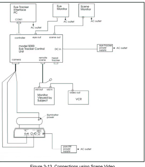
Figure 3-13. Connections using Scene Video Signal in place of Scene Camera . . . 38
Figure 4-1. Eye Tracker Main Screen with Upload Dialog Box . . . 41
Figure 4-2. Eye Tracker Main Screen - Upload Complete . . . 42
Figure 4-3. System Settings Dialog Window . . . 44
Figure 4-4. MHT Pull-down menu . . . 46
Figure 4-5. Selecting MHT Type . . . 47
Figure 4-6. Interface Program Main Screen showing MHT Transmitter Offset . . . 47
Figure 4-7. MHT Sensor Orientation . . . 49
Figure 5-1. Nine-point Calibration Target . . . 51
Figure 5-2. Set Target Points Shortcut Button . . . 52
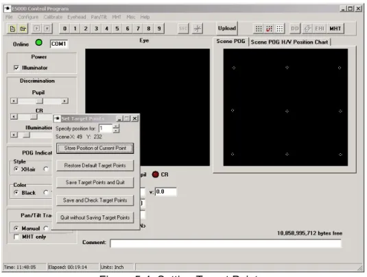
Figure 5-3. Set Target Points Window . . . 52
Figure 5-4. Setting Target Points . . . 53
Figure 5-5. Check Target Points Shortcut Button . . . 54
Figure 5-6. Check Target Points Window . . . 55
Figure 5-7. Pan-Tilt Setup Window . . . 56
Figure 5-8. Confirm MHT Calibration . . . 57
Figure 5-9. Measuring Distance from Center of Transmitter to Pan-Tilt Camera Center of Rotation . . . 58
Figure 5-10. Set Camera to Transmitter Distance . . . 58
Figure 5-11. Place Sensor between Camera and Transmitter . . . 59
Figure 5-12. Continue MHT Calibration? . . . 59
Figure 5-13. Place Sensor to Left . . . 60
Figure 5-14. MHT Sensor Calibration Shortcut Button . . . 61
Figure 6-2. Set Sensor-to-Eye Vector Button . . . 66
Figure 6-3. Setting Threshold Discrimination for Pupil and Corneal Reflection . . . 67
Figure 6-4. Pupil Outline and Corneal Reflection as seen in Eye Monitor . . . 68
Figure 6-5. Eye Monitor View showing Stable Pupil and CR Discrimination . . . 70
Figure 6-6. Speckling or Flaring around the Eye . . . 72
Figure 6-7. Eye Calibration Shortcut Button . . . 74
Figure 6-8. Eye Calibration Window . . . 75
Figure 6-9. Custom Eye Calibration Window . . . 77
Figure 6-10. Seventeen point Calibration Target . . . 80
Figure 6-11. Eye Position Offset . . . 81
Figure 7-1. Recording from Eye Tracker Main Screen . . . 82
Figure 8-1. Relation between Line of Gaze and Pupil/CR Separation . . . 94
Figure 8-2. Eye Tracker Timing . . . 95
Figure 10-1. Gaze Tracker Opening Screen . . . 103
Figure 10-2. Choose an Analysis Mode . . . 103
Figure 10-3. Load a Slide Show . . . 104
Figure 10-4. Gaze Tracker Main Screen . . . 104
Figure 10-5. Toggle Slide View . . . 105
Figure 10-6. Data Transform Window . . . 106
Figure 10-7. Test Connection . . . 108
Figure 11-1. Slide Show Wizard Step One . . . 112
Figure 11-2. Adding Slides to a Slide Show . . . 113
Figure 11-3. Setting Slide Presentation Parameters . . . 114
Figure 11-4. Advance Slide when Mouse Click is Detected . . . 115
Figure 11-5. Advance Slide after 10 Seconds . . . 116
Figure 11-6. Mouse Click or Space Bar will Advance to the Next Slide . . . 117
Figure 11-7. Completed Slide Show . . . 118
Figure 11-8. Saving the Slide Show . . . 119
Figure 11-9. Configuration Notice . . . 120
Figure 11-10. Warning Message . . . 121
Figure 11-11. The Manage Database Window . . . 122
Figure 11-12. Editing a Single Subject . . . 123
Figure 12-1. Advance to the Next Slide . . . 124
Figure 12-2. Save Data Panel . . . 125
Figure 12-3. Assigning Subject ID Number . . . 125
Figure 12-4. Subject Identifying Information . . . 126
Figure 12-5. Save Data Before Exit Prompt . . . 126
Figure 12-6. Checking Saved Data . . . 127
Figure 12-7. Recorded Sample Points for One Slide . . . 128
Figure 13-1. Apply Look Zones Box . . . 129
Figure 13-2. Look Zone Properties Dialog Box . . . 130
Figure 13-3. Look Zone Data Dialog Box . . . 131
Figure 14-1. Choosing Defaults for Fixation Options from the Gaze Trail Options
Window . . . 135
Figure 14-2. Selection of Data Type . . . 138
Figure 14-3. Summary Data for Look Zones . . . 139
Figure 14-4. Summary Data Options . . . 140
Figure 14-5. Slide Selection . . . 141
Figure 14-6. Selecting Look Zones . . . 142
Figure 14-7. Subject Selection . . . 143
Figure 14-8. Summary . . . 144
Figure 14-9. Three Factor Excel Data File . . . 145
CHAPTER 1: INTRODUCTION
The Model 504 remote eye tracker is designed to measure a person’s pupil diameter and point of gaze on a stationary (fixed) scene. The point of gaze (POG) is displayed as a cursor, a cross, or a set of cross hairs superimposed on the image the subject is viewing. The image can come from a scene camera or other video source, such as a monitor. If the data is being
recorded by the Eye Tracker program, the data file is stored on the Interface PC. If the data is being recorded by an external program, such as the Gaze Tracker program, the data file is stored on the Display PC. The data may also be exported as a real time serial data stream to an external device. Recording on the Interface PC is described in Chapter 7. Real time serial data output is described in Section 7.5. Instrument technical specifications are summarized in Section 8.4.
The auto-focus eye camera and the eye illuminator (IR beam) are contained in a pan-tilt module that automatically moves the camera and illuminator in both azimuth and elevation to follow motions of a subject’s head. The Magnetic Head Tracker system tracks the position of the subject’s head, including head rotation, within a limited field by means of a small magnet held in place by a velcro band.
The Interface PC running the Eye Tracker program serves as the experimenter’s interface with the eye tracker system. The Eye Tracker program stores calibration information in a special file. When properly calibrated, the Eye Tracker, operating through the Control unit, controls camera tracking and calculates the subject’s Point of Gaze and pupil diameter at each sample point. The Eye Tracker may also be used to record this data.
A general system description is provided in Chapter 2, followed by unpacking and installation instructions in Chapter 3. The Eye Tracker program is described in Chapter 4. System calibration and operation are described in Chapter 5. Chapter 6 describes the process of subject calibration, which must be done for each subject. Data recording with Eye Tracker is described in Chapter 7. The basic theory of operation is explained in Chapter 8. Chapter 9 will be useful for fault diagnosis should there be any problem with system function.
A variety of options are available to enhance performance of the 504 system. Some of the options are described in section 2.3.
The Gaze Tracker program runs on the Display PC. It controls the stimulus display and timing, and data recording and output. Point of gaze information is passed to Gaze Tracker from the Eye Tracker Controller via a serial connection.
Chapter 10 describes installation and calibration of the Gaze Tracker program. Chapter 11 describes the process of creating a new “configuration” or slide show. Recording and saving data is described in Chapter 12. Once the data has been recorded, the gaze path can be “played back” in real time, superimposed over the stimulus display.
What Eye Tracker calls an “Area of Interest (AoI), Gaze Tracker refers to as a “Look Zone” (LZ). These are simply zones of particular interest in the stimulus display, as defined by the user. Creating Look Zones is described in Chapter 13. Once Look Zones have been created and saved, they may be displayed or hidden in the displayed image. Data analysis and export is described in Chapter 14. The Gaze Tracker manual, contained in a .pdf file on the Display Computer in C:\ERT\bin\manuals\>, gives additional information about creating 3-D displays, and
so forth.
Appendix A provides a checklist of steps to be followed each time a subject is run. Appendix B gives a list of Eye Tracker menus and short-cut buttons, and Gaze Tracker menus and short-cut buttons. Following the usual Windows convention, once the program is running, moving the cursor over a short-cut button causes the button’s label to appear.
Chapter 2: General System Description
The Model 504 eye tracker with an optional magnetic head tracker (MHT) is illustrated schematically in Figure 2-1. The subject’s eye is illuminated by an infrared beam on the pan-tilt camera optics module. An auto-focusing lens system in the pan-tilt camera focuses an extreme close-up (telephoto) image of the eye. The pan-tilt mechanism can rotate both the illumination source and eye imaging components in azimuth (pan) and elevation (tilt) in order to follow the eye as the subject or the eye moves. A second, wide angle lens in the pan-tilt camera moves in parallel with the telephoto lens to track the general orientation of the camera. A separate scene camera may be used to record the scene being viewed by the subject. Both the pan-tilt camera and the scene camera, if used, are connected to the model 5000-control unit. Two black and white monitors,
supplied by ASL, are used to monitor the system.
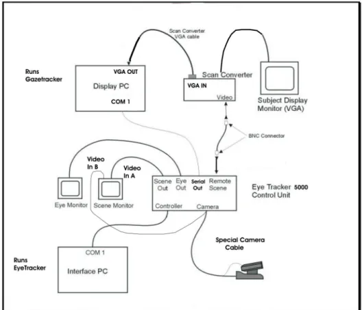
An alternate configuration, shown in Figure 2-2, assumes that the subject will be viewing a computer monitor. A scan converter is used in place of the scene camera to produce a video copy of the display viewed by the subject.
Figure 2-1. Model 504 Eye Tracking System with optional Magnetic Head Tracker
The Interface PC runs the Eye Tracker program and controls the operation of the system. The Eye Tracker program is used to calibrate both the system and the individual subject. The Display PC runs the Gaze Tracker program and controls the display shown to the subject. The Eye Tracker collects eye movement data and passes it on to the Gaze Tracker program, where it is stored.
The Model 5000 Control Unit processes the image from the close-up lens to extract the elements of interest (pupil and reflection of the light source on the cornea) and computes both pupil diameter and point of gaze. These data are displayed and output to external data ports. For a discussion of the principles used to determine eye line of gaze see Chapter 7, Theory of Operation.
The Control Unit uses pupil recognition information to control the pan-tilt camera, determining appropriate pan and tilt commands to keep the pupil image centered. The magnetic head tracker provides information about head rotation or movement even when the eyes are closed or out of the camera field of view. When this occurs, the Control Unit uses information from the magnetic head tracker (Figure 2-1) to swiftly re-position and re-focus the camera when the eye comes back into the field of view.
A hand-held remote control unit is used by the operator to manually control the camera and adjust the focus. The hand-held control unit must be used for initial calibration of each
subject.
The black and white Scene Monitor has an A/B switch to control the input source. In one position, the monitor displays the view from the pan-tilt camera wide angle lens, to permit tracking and aiming of the camera. In the other position, the Scene Monitor shows the display as seen by the subject.
Once a stable signal is acquired by the software, pupil and corneal reflection outlines and center cross hairs are displayed in the Eye Monitor over the close-up image of the eye. If the signal for either pupil or CR is lost, the outline and cross hairs disappear and no valid data is being recorded.
The point of gaze (POG) is calculated and displayed as a cursor or set of cross hairs superimposed on the scene in the Scene Monitor. The X-Y position of the eye is also displayed in the Scene POG window in the Eye Tracker main screen (see Chapter 5, Section 5.3 through 5.5).
Calibration commands and most other interaction with the operator take place through the Interface PC. Data may be recorded on the Interface PC hard disk and processed later by user-written programs or by ASL’s data analysis (EYENAL) program. For systems using the Gaze Tracker program, the Interface PC passes the data to the Display PC. The data is recorded on the Display PC by the Gaze Tracker program. Setting up communication between Gaze Tracker and Eye Tracker, and use of the Gaze Tracker program are described in Chapter 12.
The standard model 504 consists of the items listed below:
1. Model 5000 Control Unit and plug in power supply 2. Pan-tilt optics eye camera optics module.
3. Scene camera with tripod; or scan converter
4. Two b/w video monitors (one for the eye image and one for the scene image) 5. Cables for connecting the Model 5000 Control Unit to the Interface PC, to the
pan-tilt optics and scene camera, and to the two monitors.
A minimum system configuration should include all of these items, plus two PC’s supplied by the user, with minimum specifications as described in Section 2.1.5. Figure 2-3 shows the standard model 504 components.
Note that a scan converter is substituted for the scene camera if subjects will be viewing a computer monitor display.
2.1 Major Assemblies
2.1.1 Pan-tilt eye camera optics module
The pan-tilt camera shown in figure 2-3 and 2-4 normally rests on a horizontal surface, such as a table top, but it can be mounted on a tripod. A ring of near infrared LED’s
surrounding the close-up lens provides eye illumination. The power switch and connectors are located on the rear of the camera base, except for the illuminator power connector (6 vdc, 100 mA), which comes out of the rear of the camera. A separate power supply (13.5 vdc) connects to a DC power input connector on the rear panel. The transformer plugs into a standard AC wall outlet. A hand-held IR remote control unit provides manual control for pan-tilt positioning, lens focus and zoom, and various other features built into the pan-tilt camera. The camera video output is 60 Hz (NTSC) or 50 Hz (PAL) composite video format depending upon the video standard in the destination country.
The pan-tilt mechanism provides about 100/ of pan angle and 25/ of tilt capability. It may be necessary to tilt the base of the unit to achieve the necessary camera view angle. A removable knob is provided for this purpose. The tilt knob screws into a “¼ - 20” hole in the unit base plate and, when in place, can be adjusted to hold the front of the base plate between 1.25 and 1.5 inches above the table surface (see Figure 2-5). The same mounting hole can be used to fasten the unit to a tripod.
The camera has an auto-focusing close-up lens with a zoom function (Figure 2-6). The zoom setting controls the range over which the camera can be focused. At maximum zoom, the camera will auto focus over a range from about 18 to 24 inches. As zoom decreases, the width of the field of focus increases. Ordinarily, the lens need not be used at full zoom. The maximum distance at which the eye tracker can be used effectively is about 40 inches from the camera to the eye (see Figure 2.5).
The camera also provides a separate wide-angle lens with an axis parallel to the axis of the zoom lens (see Figure 2-6). The view through the wide-angle lens appears in the Scene Monitor when the A/B switch is switched to the A position. The wide-angle lens and the hand-held remote control are used during calibration to aim the camera and “find” the subject’s eye (see Section 3.3.2). Once calibration of the subject is complete, the A/B switch can be switched back to the B position. The Scene Monitor then shows the same scene as the one being
viewed by the subject.
The remote control for the camera is an IR emitting device and must be pointed at the sensor on the front of the pan-tilt camera. If the operator is sitting behind the camera, it can be adjusted from the rear by bouncing the IR beam off of a mirror, positioned in front of the
camera and angled so the IR beam is reflected into the sensor on the front of the camera. This Figure 2-5. Pan-tile Module with Tilt Knob
permits the operator to control the camera while watching the black and white monitors, which will be facing away from the subject. An amber light on the base on the front of the camera blinks when the camera receives a command from the hand-held control. If the light doesn’t blink when the remote control is operated from a position facing the front of the camera, a new set of batteries should be installed and tested in the remote control.
Except for auto-focus, pan-tilt camera functions can be controlled from
the Eye Tracker Interface program, as described in Chapter 4, but the adjustments using software are slow and not as smooth as when the hand-held control is used. The hand-held remote control is an integral part of the eye tracker system. Keep a spare set of batteries.
The Auto-focus function of the close-up lens can only be switched on/off with the hand-held remote control. It cannot be controlled from software and there is no indicator, either in the Eye Tracker program or on the camera, which tells whether Auto-focus is on or off. The only way to tell whether or not the Auto-focus is “on” is to point the camera at a stationary object and attempt to refocus the lens. Watch the behavior of the lens focus in the close-up image in the Eye Monitor. If the auto-focus wants to “fight” and over-ride the manual control, Auto-focus is On. Once the subject’s pupil is clearly focused in the frame during calibration, Auto-focus should be switched to “on.”
2.1.2 Floor Mounted Scene Camera (FMSC) or Scan Converter
A scene camera may be used to produce a video image of the same scene the subject views. This scene image provides the reference frame for the eye point of gaze measurement. A color scene camera (not provided by ASL) may be powered directly from the model 5000 Control Unit. If used, it is equipped with an 8 mm lens, and includes a standard photography tripod to support the camera. The scene camera video output is 60 Hz (NTSC) or 50 Hz (PAL) composite video format depending upon the video standard in the destination country.
If subjects will be looking at an image on a computer screen, the system includes a scan converter in place of the scene camera (see Figure 2-2). The scan converter converts the VGA computer screen image, as viewed by the subject, to a composite video signal (either NTSC or PAL standard) which is input to the eye tracker control unit as the scene video image. The scan converter is powered by its own external AC supply.
2.1.3 Model 5000 Eye Tracking System Control Unit
The Model 5000 Control Unit measures 3.25” h x 10.0” w x 10.25” d. It weighs 4.5 lb., and includes an external 12 VDC power supply. The unit front panel (Figure 2-7) contains a power switch; the rear panel (Figure 2-8) contains all necessary connectors. Basic use of the device requires the connectors labeled “Controller”, “Camera”, “Remote Scene”, “Eye Out”, “Scene Out”, and “12V DC IN”. These are the connections, respectively, to the Interface PC; the eye camera; the scene camera or subject display monitor; the eye monitor; the scene monitor; and the DC power supply respectively. Other connectors support various options or secondary functions such as communications with a magnetic head tracker and data output to an external device. The “HMO/PT” slide switch should be in the “P/T” position for use with pan-tilt optics.
The connections are summarized as follows: Controller - from Interface PC (COM 1) Camera - from eye-tracking camera
Remote - from Scan Converter (subject display monitor) Eye Out - to Eye Monitor
Scene Out - to Scene Monitor 12 VDC In - from power transformer
The control unit houses the processing board that receives video input from eye and scene cameras, recognizes pupil and corneal reflection (CR) features in the video eye image, computes line of gaze, communicates with the Interface PC, controls the pan-tilt mechanism,
Figure 2-7. Model 5000 Control Unit Front Panel.
and superimposes feedback outlines, cross hairs, and cursors on the eye and scene video signals for monitor display. When an optional magnetic head tracker is used, the processing board also communicates with the magnetic head tracker (MHT) and uses the head position data from the MHT sensor to help control the pan-tilt mechanism.
2.1.4 Monitors
As shown in Figure 2-2, the system includes two black and white video monitors. One is an Eye Monitor, which shows a close-up image of the pupil, the second is a Scene Monitor, which shows the scene being viewed by the subject. The Scene Monitor is equipped with an A/B switch. In the “B” position, the Scene Monitor shows the view through the wide-angle (long-range) lens on the pan-tilt camera; in the “A” position, the Scene Monitor shows the scene as viewed by the subject. During successful data collection, cross-hairs indicating the Point of Gaze will be superimposed on the scene or stimulus frame.
The Eye Monitor displays the image from the camera close-up lens. When the eye tracker is functioning properly, a white outline is superimposed over the image recognized as the pupil and a black outline is superimposed on the image recognized as the corneal reflection (CR). A white set of cross hairs designates the center of the pupil and a black set designates the CR. The white outline of the pupil is offset slightly from the pupil for greater visibility in the display.
If monitors are supplied by the user, video cables must also be supplied. The monitors may be black and white or color and must accept a standard EIA (black and white) or NTSC (color) composite video signal (CCIR or PAL if 50 Hz cameras are being used).
2.1.5 Eye Tracker Interface PC
A computer may be supplied by ASL to serve as the Interface PC, but is usually supplied by the user. The computer serves as the user interface device and as a data-recording device. ASL always supplies an Eye Tracker Interface program, which runs on this computer.
System requirements for the Interface PC are an IBM compatible PC capable of operation with Windows 95, Windows 98, Windows NT, 2000, XP, or DOS. A computer that can run only DOS is limited to using only the DOS version of ASL’s Eye Tracker Interface Program. The computer must have COM1 or COM2 serial ports available using standard interrupts and device addresses. The minimum recommended system is a 200 MHz Pentium, but slower systems will work adequately as well. In these cases consult ASL
2.1.6 Software
The Eye Tracker software is run from the file “E5Win.exe,” which will be on the Interface PC in the C:\ProgramFiles\ASL Eye Tracker\EyeTracking\> directory once the program has installed itself (spaces in the path name are intentional). The EYEPOS software package necessary to operate the eye tracker and record data is provided as a standard part of the Eye Tracker. The EYEPOS software is included on a CD ROM, labeled “EyeTracker Software”, or on a floppy disk labeled “EYEPOS”. Also included on the CD ROM or on a set of floppy disks is the EYENAL data analysis software, which includes a “CONVERT” function to convert binary data files to ASCII, and ACCESS software to allow access to binary data files from user written
C programs. It’s a good idea to set up a short-cut on the desktop from which to start the Eye Tracker. It’s also a good idea to keep track of which version of the Eye Tracker software you are using. Getting technical assistance may require having this information.
The Gaze Tracker program installs itself on the Display PC in C:\ERT\bin\> The file is named GazeTracker.exe.
2.2 Interface Description
The Eye Tracker Interface PC is connected to the Model 5000 Control Unit with a serial, RS232 cable from COM1 on the PC to the “Controller” connector on the model 5000 control unit (see Figures 2-2, 2-3, and 2-8). If an optional magnetic head tracker is being used it interfaces to the connector labeled “Head Tracker,” with a serial (RS232) cable (Figure 2-8). Real time serial data can be exported to an external device via connector labeled “Serial Out” (RS232). The interface protocol is described in Chapter 6. The video images from either the scene or pupil monitor outputs may also be videotaped.
The XDAT port on the Control Unit may be used to input digital data from an external device, to indicate external events. These signals are numbered consecutively as they are received and inserted into the data stream.
2.3 Options
Described below are some additional components and software options, available from ASL, which may further enhance system operation.
2.3.1 Binocular and High Speed 504
Eye position data is normally sampled at 60 Hz. The model 504 is available with a High Speed (HS) option, capable of 60, 120, and 240 Hz sampling rates. In addition there is a remote Binocular option consisting of two sets of optics to remotely track left and right eye movements.
2.3.2 Magnetic Head Tracking Hardware (MHT)
The magnetic head tracking option (MHT) is a small unit that determines head position and orientation with good accuracy in six degrees of freedom (in X, Y, and Z dimensions). The head tracker output can be recorded independently of the eye tracker by a host computer or by the Interface PC. When used with the model 504 eye tracker system, the MHT is used by the Control Unit to assist in aiming the camera to keep the pupil in focus.
The magnetic reference source is a stationary transmitter mounted behind the subject which generates a magnetic hemifield. Head position is measured in six degrees of freedom at distances of up to approximately 36 inches from the transmitter. The MHT option includes a control unit which powers the device, a magnetic transmitter (reference), and a small sensor or receiver which is attached to a Velcro head band worn by the subject. Nylon screws are provided for mounting the magnetic transmitter module. A cable is provided to connect the MHT control unit to the “Head Tracker” port on the Control Unit (see Figure 2.8).
the subject. However, if circumstances permit, it may be advisable to permanently mount the transmitter on a wooden shelf located behind the subject to prevent accidental movement of the transmitter. If the transmitter is moved, the system must be re-calibrated. MHT performance can be affected by large pieces of nearby metal or anything else, such as an AC power line, that causes magnetic field distortion. Consult ASL for details.
Chapter 3: Installation
3.1 Unpacking and AssemblySetting up the apparatus may be aided by consulting Figures 2-1, 2-2, and 2-3, in the previous chapter and Section 3.3 and Figures 3-11 through 3-13 in this chapter. Except for the connectors on the back of the Interface PC and the Display PC, which are supplied by the user, the connectors on the Control Unit, Scan Converter, MHT controller, the camera, and the two black and white monitors are marked with colored tabs. The cable-ends, including the RS232 serial cables which connect to COM 1 on the user-supplied PC’s, are marked with matching colored tabs. Connecting the cables is described in Section 3.3.
3.1.1 Control Unit
Locate the model 5000 Eye Tracker Control Unit and unwrap the protective material. Be sure that the power switch on the front panel is in the OFF (down) position (Figure 2-7).
For use with model 504 pan-tilt optics, be sure that the slide switch on the rear panel is in the “P/T” position (Figure 2-8).
Locate the 12VDC power supply module and connect it to the “DC Power” connector on the Control Unit. Connect the other side to an AC power outlet. The power supply is input rated for 100 - 240 VDC, 50 or 60 Hz. The LED on the front panel of the Control Unit should remain off until the power switch is switched on.
3.1.2 Pan Tilt Optics
The pan tilt module will be in a small box in one of the large shipping boxes. It is packed in protective foam along with a 13.5 VDC power supply, remote control, and the removable tilt knob. Place the optics module on a flat surface or, if it will be mounted to a tripod, fasten it to the tripod using the “1/4 - 20” hole under the nonmoving base. Be sure the power switch is in the off position. Connect the 13.5 VDC supply to the “DC IN” connector.
3.1.3 Scene Camera
If a scene camera (FMSC) was ordered from ASL, locate the scene camera in one of the shipping boxes. It will be a very small camera about 1in. sq (2.54cm sq). Locate the scene camera tripod and adjustable tripod head. The tripod will usually be in the manufacturer’s box in one of the two-foot cube boxes. Mount the scene camera on the tripod. The handle on the tripod head, which turns to loosen and tighten, may be used to position the camera.
3.1.4 Scan Converter
If a scan converter (AverKey Micro) was ordered from ASL, find the Scan converter box, carefully unpack the components and place them near the Display Computer and monitor. Note that use of the scan converter is appropriate only if the eye tracker subjects will be looking at a VGA computer display. There is no mechanical assembly required; cable connections are described in Section 3.3 (“Interconnections”).
If the Eye Tracker Interface PC has been supplied by ASL, locate the computer, monitor, keyboard, and mouse, and assemble in the usual fashion. If supplied by ASL, the computer will have the eye tracker software pre-installed. Software installation is discussed in Section 3.4. The Eye Tracker program is discussed in Chapter 4. The instructions for installing the Eye Tracker software are also supplied with the program CD. It is assumed that the user is familiar with standard PC assembly and operation. If not, please consult ASL.
3.1.6 Magnetic Head Tracker
The magnetic head tracker (MHT) unit comes individually packaged. The package contains a control box, a source module with cable and connector, a sensor module with cable and connector, and a manual with one or more floppy disks. The MHT system may be either an Ascension “Flock of Birds” or a Polhemus “FASTRAK” or “ISOTRAK” type system. Consult ASL for comparative details.
The MHT transmitter (source) module must be mounted to a stable, nonmetallic surface using the nylon screws provided. The transmitter should be mounted so that it will be just above and behind the subject’s head. When the subject’s head is in the nominal center (or average) position, the sensor worn by the subject should be 10-12 inches from the transmitter. Placement and mounting of the transmitter is discussed in Section 3.2.2 and illustrated in Figures 3-9 and 3-10.
If possible, the transmitter should be oriented so the x-axis is directed toward the subject and so that the y-axis points down. The front of the transmitter, which faces toward the subject, has a raised, contoured face. It is also very important that the transmitter be rigidly supported, since any motion or dislocation of the transmitter will introduce errors into the data.
It is a good idea to mark the sensor, worn by the subject, with an arrow showing the “up” (Y+) direction (Figure 3-1). During calibration, the software is “taught” left/right, up/down, and near/far directions. During data collection, MHT calibration information is used to track the subject within the three-dimensional field. Failure to position the sensor in the same orientation as it was held during calibration will result in errors in the data.
3.2 Component Placement
3.2.1 Optics and Scene Relationships
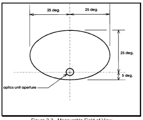
The standard placement of the pan tilt module and the resulting “measurable field of view” - the field within which accurate measurements may be made - is shown in Figure 3-2. The measurable field of view is shown in another way by figure 3-3.
Figure 3-1. MHT Sensor marked to show “up” (Y+).
The measurable field extends symmetrically to either side of the camera and above the camera centerline as much as 25 degrees, but only extends a small distance below the camera. This is because the upper eyelid begins to occlude the camera’s view of the eye when the subject looks below the camera. For this reason, ideally the camera module should be placed near the bottom of, or just below, the desired field of view (Figure 3-4), near the horizontal center of the field. Such an arrangement minimizes eyelid occlusion of the pupil and provides left to right symmetry.
Figure 3-3. Measurable Field of View from Subject’s Point of View.
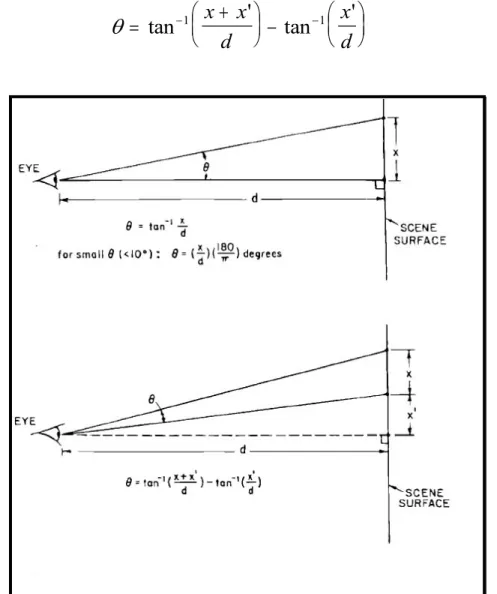
If the line of sight is perpendicular to the surface being viewed, the visual angle, theta (2) between two points on a flat surface may be calculated as:
When theta is small (Figure 3-5), less than about 10 degrees, the calculation can be simplified as:
When the line of sight deviates from the axis perpendicular to the surface of the scene (bottom of Figure 3-5), theta is calculated as:
θ
=
−tan
1x
d
θ
π
=
x
d
180
θ
=
+
−
− −tan
'
tan
'
1x
x
1d
x
d
Figure 3-5. Computation of Visual Angle between Points on a Flat Surface.
Less than ideal positioning may be required for a particular application or experiment. Figures 3-6, 3-7, and 3-8 show typical placements of the components.
Figure 3-6. Camera placed beside Monitor.
Figure 3-7. Camera placed in front of a very large Monitor.
The pan-tilt camera may be placed anywhere so long as the following constraints are observed:
1. The optics unit to eye distance (“d" in Figure 3-2.) must be in the range of 18-40 inches. The optimal distance is from 26 to 32 inches. There are trade-offs here. If the distance d is smaller, the eye image captured by the close-up lens fills the monitor screen and reflection of stray light from other areas of the subject’s face is minimized. But under these conditions, if the subject moves during data collection, compensatory tracking motions of the camera have to go through a greater angular distance and require slightly more time to track the eye.
2. There must be a clear optical path between the optics unit and the eye.
3. Wherever the camera is placed, the measurable field of view will be about 25 degrees visual angle to either side of the optics, about 25 degrees above the optics and about 10 degrees below the optics as shown in Figures 3-2, and 3-3. The method for calculating visual angles using measured distances is shown in Figure 3-5.
4. If the subject is seated in front of a computer monitor (Figure 3-4), the person’s eye should line up just above the middle of the monitor screen. A chair, such as an office or secretary’s chair with a height adjustment, may facilitate accurately positioning the subject.
5. Although the distance between the pan-tilt camera and the eye is restricted, there is no restriction on eye-to-scene distance. The scene may be a video display, a slide
projection, or any other display or natural scene. The scene may be any distance from the eye, so long as the area to be scanned falls within the visual field defined by Figures
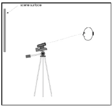
Figure 3-8. Camera mounted on Tripod in front of Projection Screen.
3-2, 3-3, and 3-5. Errors in point of gaze measurement due to head motion will be minimized, however, when the scene being viewed by the subject is at the same distance from the subject as the front of the pan-tilt module. Such optimal placement may not always be practical, and other arrangements do not preclude successful gaze measurement.
In Figures 3-4, 3-6, and 3-7, the scene being viewed is a monitor. Note that only figure 3-4 satisfies the optimal conditions by placing the optics module and scene surface the same distance from the subject, and placing the optics module just below the scene but centered horizontally.
Figure 3-6 shows the optics placed to one side of the monitor. This will work well so long as the upper right corner of the monitor remains within about 25 degrees visual angle from the pan-tilt camera.
If the surface to be viewed by the subject is especially large, like the very large monitor shown in Figure 3-7, the optics module may be placed in front of the monitor. If the pan-tilt module were placed below this large monitor, points at the top of the monitor screen would probably be more than 25 degrees visual angle from the pan-tilt optics, and gaze directed at the top of the monitor screen would be beyond the measurable field. In other cases, such as a subject viewing a large projection screen, the pan-tilt optics module may have to be even further from the scene surface, as shown in Figure 3-8.
Regardless of how the camera and viewing surface are positioned, there must be a method for displaying a nine-point calibration target on the display scene surface. Display of the calibration target is explained in Section 5.2.5.
If a separate scene camera is used to record the scene being viewed by the subject (Figure 2-1), it should be placed as close to the subject’s head as possible so that the scene camera image shows the same perspective as that seen by the subject. A scene camera is not required at all if the source of the scene is a video recording, presented using a scan converter (Section 2.1.2 and Figure 2-2).
Although a tripod is provided, a scene camera may be mounted in any way that is convenient. It is recommended that the scene camera be mounted securely enough so that its position will not be changed accidentally by someone bumping it or brushing against it. As described in Chapter 5, system calibration requires that the scene camera be stationary; some calibration procedures must be repeated if it moves.
3.2.2 Magnetic Head Tracker Placement
If the system is equipped with a magnetic head tracker (MHT), the MHT transmitter (source) module must be mounted to a stable, nonmetallic surface using the nylon screws provided. It is suggested that the transmitter be mounted so that it will be just above and behind the subject’s head, as shown in Figure 3-9, so that when the subject’s head is in the nominal center, or average position, the transmitter is about 6 inches behind the head. The transmitter creates a three foot magnetic hemi-field, so these distances are not rigidly prescribed.
y-axis points down. It is very important that the transmitter be rigidly supported, since any motion of the transmitter will introduce errors into the data.
A common mounting arrangement for the transmitter is a wooden post with a heavy metal or wooden base, as shown in Figure 3-10. Mounting the transmitter to a wooden shelf attached to a wall behind the subject makes an arrangement that is even less susceptible to accidental movement.
Figure 3-9. Placement of Magnetic Transmitter.
Figure 3-10. Magnetic Transmitter Mounted on Wooden Post.
3.3 Interconnections
Figure 3-11 shows the connections for the model 504 Eye Tracker with an optional magnetic head tracker. As noted at the beginning of this chapter, all of the cable connections are color-coded. Also see Figures 2-1, 2-2, 2-4, and 2-8.
Figure 3-11. Connections for Model 504 Eye Tracker with Magnetic Head Tracker.
3.3.1 Pan-Tilt Optics Module Connections
1. Be sure that the system power and power to the pan-tilt module are OFF.
2. Connect the 13.5 VDC power supply to the pan-tilt module “DC-IN” connector, and to an AC wall outlet.
3. Find the camera-to-control unit cable (white/red dot). The cable has a 25-pin D-connector at one and, and multiple D-connectors at the others. The standard length is 25 ft. (7.6 meters), although other lengths are available.
4. Plug the 25-pin D-connector into the connector labeled “Camera” (white/red dot) on the Model 5000 Control Unit (Figure 2-8). If there is a small cable with a BNC connector splitting off from the 25-pin connector, it should be connected to the A/B switch on the Scene monitor.
At the other end, the Camera cable splits into five ends:
A. Connect the plug with the yellow end into the socket labeled “VIDEO OUT” (yellow dot) on the rear panel of the pan-tilt camera;
B. Connect the yellow/blue end to the socket labeled “VISCA IN” with (yellow/blue dot) on the rear panel of the pan-tilt base;
C. Connect the white/blue end to the other white/blue cable extending out from the neck of the pan-tilt camera;
D. Connect the green blue end to the small power supply with the came color code; E. Plug the remaining socket into the connector on the rear of the moving head on the pan-tilt assembly (see Figure 2-3 and 2-4). There may be a wire coming out of the back of the camera, instead of a connector on the camera itself.
Strain-relieve the camera cable at the camera end by taping it to the table or tripod leg, etc. Cable ties or other strain relief techniques may be used. Be sure that the illuminator cable (the lead that is connected to the moving part of the pan-tilt mechanism) has enough slack to accommodate full panning motion of the mechanism. If the point where the cable separates into multiple leads is close to the pan-tilt rear panel there will be sufficient slack.
3.3.2 Wide Angle Locating Camera Lens
The wide angle lens is used as an aid in locating the subject’s eye. Due to the small field of view associated with the close-up lens on the pan-tilt camera, it can be extremely
difficult to acquire a close-up image of the eye when the subject is being calibrated (to “find” the subject’s eye in the close-up lens). The wide angle lens on the pan-tilt camera (see Figure 2-6) provides a separate video signal that does not pass through the Control Unit. The wide angle lens has an axis which is parallel to the axis of the close-up lens so the two move and point in parallel. The Scene Monitor shows the view through the wide-angle lens when the A/B switch on the Scene Monitor is switched to the B position (Figure 2-2). The Eye Monitor shows the view through the close-up lens.
It helps to aim the camera if the glass face of the Scene Monitor (switched to the wide-angle lens) is marked with a small dot, using a magic marker, to indicate where the close-up lens is pointing. Use the handheld control to aim the wide-angle lens at a stationary object such as the MHT transmitter. Position the image of the object so it is in the center of the Scene Monitor screen. Find the object in the close-up lens and center it in the Eye Monitor. It may require moving the camera slightly until a shadow crosses the Eye Monitor, and then focusing the close-up lens to bring the object into view. With the close-up lens focused on the object, use the magic marker to make a small dot on the glass screen of the Scene Monitor to mark the center of the image of the stationary object. The small dot can later be used to center the wide-angle lens on the subject’s eye.
3.3.3 Obtaining an Eye Image
When a subject is seated, position the A-B switch on the Scene Monitor to the B channel to show a wide angle view from the camera.
Use the Pan-tilt remote control to aim the camera at the subject. The Scene Monitor will show an image of the subject’s face. The Eye Monitor will show a very small, magnified portion of what the wide angle lens sees. The Eye Monitor image may or may not be in focus.
Use the Pan-tilt remote to position the eye in the center of the Scene Monitor, using the small dot as a guide. If the illuminator beam is ON, it will appear as a bright disk on the
subject’s face. Try to position the illuminator beam over the eye.
Once the subject’s eye is centered in the Wide angle field of view it should also be in, or near, the field of view of the close-up lens. Turn auto-focus off, and use the zoom buttons on the remote control to bring the image of the subject’s eye into focus in the Eye monitor. Switch auto-focus back on.
3.3.4 Eye Tracker Interface PC Connections
Use the cable provided (RS232 cable with green dot) to connect the port labeled
“Controller” on the Control Unit to the COM1 port on the Interface PC. If it is necessary to use a different COM port please consult ASL.
3.3.5 Black and White Monitors
Connect a video cable from the Eye Monitor video input (orange dot), to the Control Unit connector labeled “Eye Out” (orange dot). Connect a video cable from the Scene Monitor video input, (blue dot) to the Control Unit connector labeled “Scene Out” (blue dot).
3.3.6 Magnetic Head Tracker Connection
The MHT transmitter (source) and sensor modules attach to connectors on the MHT electronics unit. Connect one end of the MHT interface cable (yellow/red dot) to the RS232 port on the MHT control unit marked with a yellow/red dot. Connect the other end of the MHT
interface cable to the model 5000 Eye Tracker Control Unit connector labeled “Head Tracker,” also marked with a yellow/red dot. Set the DIP switches on the MHT electronics unit for 19200 Baud, RS232 communications. All switches will be down except switch number 0ne which is up. (consult manufacturer’s manual packaged with the MHT system for proper DIP switch
settings). The MHT system type (Flock of Birds) must be set in the interface program (e5win.exe) before trying to establish communications between the Eye Tracker Control Unit and the MHT. The system type can be set through the MHT pull down menu in the Eye Tracker program (see section 4.2.4).
3.3.7 Direct Use of Scene Video
If the subject will be viewing a video image (e.g., a videotape displayed on a monitor) the same video signal can be used directly as the scene video signal for the eye tracker, rather than using a separate scene camera. If the subject will be viewing a computer screen, a scan converter can be used to convert the computer image (e.g., VGA) into a composite video signal, which in turn can be used as the eye tracker scene video signal. ASL can supply a scan converter instead of, or in addition to a scene camera. Connections for these configurations are shown in figures 3-12 and 3-13 (also see figure 2-2)
.
Figure 3-12. Connections using Scan Converter to supply Scene Video Signal.
3.4 Software Installation
The Eye Tracker software is shipped on a CD. The software will be installed on the hard drive if the Eye Tracker Interface PC has been supplied by ASL. If the computer was not supplied by ASL, locate the CD labeled “Eye Tracker Software” and follow the directions on the label to install. The disk should auto-run when it is put into the drive.
As discussed in Section 2.1.5, system requirements for the Interface Computer are an IBM compatible PC capable of operation with Windows 95, Windows 98, NT, 2000, or XP if using the Windows eye tracker interface, or DOS if using the DOS eye tracker interface. The computer must have available COM1 or COM2 serial ports using standard interrupts and device addresses. The minimum recommended system is a 200 MHz Pentium, but slower systems will
Figure 3-13. Connections using Scene Video Signal in place of Scene Camera.
work, so long as they can effectively run Windows 95, 98, or NT. Running other simultaneous applications that take up a significant portion of the PC’s processor time may cause eye data to be lost. When not recording data the only consequence of the PC not having enough time will be a sluggish interface program display.
Chapter 4: The Eye-Tracker Interface Software
All of the original Eye Tracker manuals are available as .pdf files on the hard drive on the Interface Computer, in C:\Program Files\ ASL Eye Tracker\ Manuals.
The Eye Tracker software package contains the Eye Tracker user interface program (E5win.exe) that runs on the Interface PC. The program contains configuration information that must be uploaded to the model 5000 Control Unit to establish communication among the system components. The following sections assume that all appropriate interconnections have been made and software installed, as described in Chapter 3. This manual also assumes that the Windows interface program (e5Win) will be used. ASL can provide a manual upon request that describes the operation of the DOS Interface program (e5000).
4.1 Uploading Program Information to the Control Unit
Power up the model 5000 Control Unit. If it is already powered up from a previous use, use the power switch to cycle it off and back on again to be sure that it is “reset” and any stored information has been erased.
Open the Eye Tracker Interface program (e5Win) by:
clicking on the Start button /Programs /ASL Eye Tracking /Eye Tracker Interface; double clicking a corresponding desktop shortcut; or;
using Windows Explorer to navigate to the “Eye Tracking” directory (under C:\ProgramFiles\ASL Eye Tracker\EyeTracking\>) and double clicking e5Win.exe.
The Eye Tracker interface program main screen will appear along with a pop up window called “Upload to Series 5000 Control Unit” (Figure 4-1). If necessary, use the COM Port menu box to specify the PC COM port actually being used (the default is COM1). If necessary, use the Baud Rate menu box to set the proper baud rate. These settings are stored with the program. Once they are set up, they will carry over each time the program is started.
Note: ASL Series 5000 Control Units with serial # 1264 and higher have a baud rate of 115,200 K baud. ASL Series 5000 Control Units with serial # 1263 and lower have a baud rate of 57,600 K baud.
The FPGA and DSP files contain information that is written to the Control Unit once “Upload” is begun. The file names should automatically be set to the proper files. These files may be updated when a new version of Eye Tracker is installed.
Click “Start Upload.” Progress bars on the Upload window will show programming information being uploaded, first to the field programmable gate array (FPGA), and then to the digital signal processor (DSP) in the Control Unit. After a successful upload, the pop up window will disappear and the green “On Line” light at the upper left of the screen will be on.
If errors are encountered, the pop up will not close, and the scrolling upload display window will contain an error message with a suggestion for how to proceed.
Once the Control Unit has been “loaded,” the information it contains will continue to run until the power is turned off. It is not possible to reload software to the control unit until the unit has been powered off and back on to “reset” it. Recycle the Control Unit by turning the power off, wait for 15 or 20 seconds, then turn the unit back on.
The Upload process may be re-started by clicking the Upload button on the interface, or
by selecting “upload to control unit” from the Eye Tracker Configuration menu. If an attempt is made to reload the control unit without first resetting it, a pop up message will prompt the user to re-cycle power to the Control Unit.
The user interface program (e5Win) is used to change settings, such as pupil and corneal reflection discrimination thresholds, to launch procedures such as calibration, and to record data on the Interface PC. All eye tracking functions are performed by the model 5000 Control Unit. Once proper settings are established, and if data is not being recorded, the eye tracker will continue to function normally even if the cable to the Interface PC is disconnected. 4.2 E5000 User Interface Program
The E5000.exe program is a DOS version of Eye Tracker that can be used in place of e5win.exe, the Windows version. Simply double click e5000.exe, in the EYEPOS directory, instead of e5Win.exe. A separate manual is available from ASL that describes system operation in terms of the DOS Interface. Here it is assumed that e5Win (windows version) is
Figure 4-1. Eye Tracker Main Screen with Upload Dialog Box.
being used.
4.2.1 User Interface Screen
Once the FPGA and DSP information has been successfully uploaded to the Control Unit, the green “Online” light, near the top left of the interface program screen, should be on. If this light remains red, the Upload was unsuccessful and must be repeated.
The main interface program window has a menu bar at the top, a shortcut bar directly underneath the menu bar, a column of controls extending down the left side of the screen, two graphics windows labeled “Eye” and “Scene POG,” and some additional digital information displayed below the graphics windows (Figure 4-2). A list of the menu choices appearing under each pull-down menu - File, Configure, Calibrate, etc. - is given in Appendix A2.
The controls on the left side of the screen consist of standard windows slide switches,
check boxes, and radio buttons. The data displays consist of indicator lights to indicate “on-line” or “off-line,” valid pupil and CR recognition (both red in Figure 4-2), and text windows displaying COM port assignment, PC time of day, elapsed time, free disk space, point of gaze coordinates (“Scene POG”), pupil diameter, external data values (XDAT), and data file
information. The “on-line” indicator light and COM port assignment displays are at the top of the control column. Other data displays are beneath the two graphics windows. When the
magnetic head tracker is connected and enabled, an additional data display opens beneath the Scene POG window, showing the magnetic sensor position and orientation coordinates in X, Y, and Z dimensions.
When the system is operating correctly and after a subject has been calibrated, the “Eye” graphics display box at the top center of the screen shows pupil and corneal reflection (CR) center positions and diameters as detected by the eye tracker. The pink pupil center cross hairs and blue CR center cross hairs are essentially the same as the white and black cross hairs that show pupil and CR centers on the Eye Monitor. The pupil and CR circles shown on the screen are not the same as the pupil and CR outlines displayed on the Eye Monitor. The computer display simply draws circles about the cross hair positions with diameters proportional to detected pupil and CR diameters. These circles do not show the actual pupil and CR outlines detected by the eye tracker. True outlines are displayed on the black and white Eye Monitor.
A after a subject has been successfully calibrated, the graphics window labeled “Scene POG” shows a point of gaze cursor. This is essentially the same as the cursor movement on the black and white Scene Monitor. Target points are also displayed in the “Scene POG” window. During data collection, the Scene POG window will show active eye movements, but these are not superimposed on the scene as viewed by the subject. The black and white Scene Monitor, switched to “A,” shows the monitor screen or other scene the subject is viewing, with eye position cross hairs superimposed.
If the Model 5000 Control Unit is not running (powered off or reset) or if the cable connecting the Interface PC to the Control Unit is disconnected, the light labeled “On line”, at the top left of the screen will turn red. If the communication is reestablished, for example by reconnecting the cable, this light will change back to green.
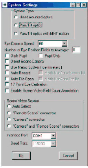
4.2.2 System Settings
Pull down the Configure menu by clicking on “Configure” in the menu bar at the top of the screen, and select “System Settings” to pop up the System Settings dialog window (Figure 4-3). Use the radio buttons under “System Type” to select the system type that reflects the current hardware configuration (Pan-tilt optics with MHT option). Set the eye camera speed (60 Hz) to correspond to the update rate of the eye camera being used by clicking on the down arrow next to the corresponding camera speed box and selecting from the drop down list. (If an optional high-speed camera is being used, the camera dip switches must be properly set for the selected update rate). The “Eye Camera Speed” setting in the System Settings window does not control the camera update rate, it merely informs the program of the type of eye camera being used.
Using the drop down list in the System Settings window, assign a COM port (usually COM1) as the interface program port. Be sure that this assignment corresponds to the physical connection between the Com port on the Interface PC and the “Controller” port on the eye tracker Control Unit.
Before being saved or output as valid X-Y eye position data, the individual samples are averaged. The number of samples being averaged is specified by the item labeled “Number of eye position fields to average” (set to zero in Figure 4-3). Simply type in the desired number of samples to be averaged. The recommended value for the pan-tilt optics system is 4. This means every eye position value output to the data file will be averaged with the previous 3 values before being displayed or recorded. To eliminate any averaging, enter 1 or 0. Only
Figure 4-3. System Settings Dialog Window.
gaze coordinates are averaged; neither pupil diameter nor any other recorded values are averaged.
Sample averaging is not the same as the criteria used to determine the start and end of an eye fixation, and its location. These criteria are discussed in Chapter 7 for Eye Tracker and Chapter 14, Section 14.1.2 for Gaze Tracker.
It is important to note that after a period during which a pupil was not recognized (no valid gaze measurement could be made) the first valid measurement is not averaged. The next measurement is averaged with the previous valid field, and the number of fields averaged increases in this way until the specified value is reached.
The check boxes on the System Settings window usually should be left unchecked. The 17-point calibration capability is explained in section 6.4.3 and the auto Eyedat function is explained in Chapter 7. “Use Metric System” applies only to setup of a magnetic head tracker for use with pan-tilt optics, as discussed in section 5.1.4. The other two check boxes do not apply to pan-tilt optics and should be left unchecked.
The “Scene Video Source” radio button should normally be left on “Auto Select” when using pan-tilt optics. When “System Type” is set to “Pan-tilt Optics” or “Pan-tilt Optics with MHT option” the system will automatically select the “Remote Scene” connector (on the Control Unit rear panel) as the scene video source. When using head-mounted optics with a head mounted scene camera, the scene video signal is usually part of the cable that connects to the “Camera” connector on the Control Unit.
Click “OK” to save the system settings and close the System Settings dialog window.
If program information has been properly uploaded to the Control Unit and the COM ports have been properly assigned, the “Online” light near the top left of the main screen should be green to indicate that the PC is communicating with the Control Unit. If this light is red, indicating lack of communication between the PC and the Control Unit, check connections and try uploading software to the Control Unit again. (To upload, turn off the Control Unit, exit the interface program and follow the directions in Section 4.1).
4.2.3 Saving and Retrieving Default Data
The current subject calibration data and system configuration settings are stored in the same directory as the E5Win program, in files called E5000.CAL and E5000.CFG, respectively. When a pan-tilt optics module is being used (model 504), information about the pan-tilt module settings and calibration information - the camera’s location with respect to the magnetic head tracking system (MHT) - is stored in a file called E5000.PTC. (Calibration of the MHT is
explained in Chapter 5.) These files are automatically updated whenever changes are made to the data they contain, and are loaded whenever the Eye Tracker program is started. For example, E5000.CAL is automatically updated at the completion of every subject calibration. Thus, the last calibration performed is remembered and reloaded the next time the Eye Tracker program is run. Similarly, the E5000.CFG file is updated whenever <OK> is clicked to exit from the “System Settings” dialog window.
To save one of these default files for future use, or to retrieve an old file previously saved, use the “Save As” or “Read” selections from the corresponding pull down menu. Access
the E5000.CAL file from the “Calibrate” menu; access the E5000.CFG file from the
“Configuration” menu; and access the E5000.PTC file from the “Pan-tilt” menu. For example, to save a particular set of subject calibration data, use the “Save As” selection on the “Calibrate” menu. In response to the prompt, enter a file name other than E5000.CAL, such as
PETER.CAL, and click <Save>. To use subject calibration data previously saved, select “Read” from the “Calibrate” menu, browse to the previously saved file, highlight it and click <Open>. It will be used as the current data until overwritten by a new calibration.
The same file manipulations can be done with Windows Explorer. Simply rename the E5000.xxx file to prevent its being overwritten, and rename it back to E5000.xxx (in the same directory as the E5Win program) to re-use it.
4.2.4 Enabling the Magnetic Head Tracker
The following section applies only if an optional magnetic head tracking (MHT) system has been connected as described in Sections 2.3.2 and 3.3.4.
The MHT pull down menu has the following choices, shown in Figure 4-4:
The “Set boresight” command will be grayed (inactive) until the MHT system is enabled. Before attempting to enable the MHT system for the first time, choose “Select MHT System” and be sure the pop up window, labeled “MHT Type” shows the type of MHT hardware actually being used (Figure 4-5). If not, activate the drop down menu and select the proper type. If unsure of the proper type, consult ASL. We are using the Ascension “Flock of Birds” in our system.
Click on “Enable“ from the MHT pull-down menu to start communication between the Eye Tracker program and the MHT system. Alternatively, click the MHT button at the far right side of the shortcut bar. If communication is successfully established with the MHT system, the MHT data display, labeled “Transmitter Offset” will appear under the “Scene POG” display window and the MHT button will appear to be depressed (Figure 4-6).
Figure 4-5. Selecting MHT Type.
Figure 4-6. Interface Program Main Screen showing MHT Transmitter Offset.