System Administrator / User Manual
Copyright © 2001 VODAVI Technology, Inc. All Rights Reserved
This material is copyrighted by VODAVI Technology, Inc. Any unauthorized reproductions, use or disclosure of this material, or any part thereof, is strictly prohibited and is a violation of the Copyright Laws of the United States (17 U.S.C. Section 101 et. seq.).
VODAVI reserves the right to make changes in specifications at any time and without notice. The information furnished by VODAVI in this material is believed to be accurate and reliable, but is not warranted to be true in all cases.
FCC I N F O R M AT I O N :
» FCC part 68 ID is: 4U9USA-36143-VM-T » Ringer Equivalence = 0.7B
mlj/2001
LIFE SUPPORT APPLICATIONS POLICY
VODAVI Technology, Inc. products are not authorized for and should not be used within Life Support applications. Life Support systems are equipment intended to support or sustain life and whose failure to perform when properly used in accordance with instructions provided can be reasonably expected to result in significant personal injury or death.
VODAVI Technology, Inc. warranty is limited to replacement of defective components and does not cover injury to persons or property or other consequential damages.
System Capabilities ...1-3
Basic Features ...1-3
Installing the Voice Mail System ...1-7
Box Contents ...1-7
Connections ...1-7
Installing the Memory Expansion Board ...1-8
Specifications ...1-8
Voice Mail Integration Programming ...1-10
DHS and DHS-E ...1-10
Other Vodavi Systems ...1-12
MiniVoice Programming Devices ...1-14
Programming System Functions Via Telephone ...1-16
Administrator Options ...1-17
Programming System Functions Via Computer ...1-29
PC Accessibility ...1-29
Navigating in the System ...1-30
Menu Option Screens ...1-31
Signing On ...1-31
Programming Menus ...1-32
Open and Close Schedule ...1-33
System Numbering Plan ...1-34
Invalid Digits ...1-39
Auto Attendant Configuration ...1-40
System Clock Adjustments ...1-42
Version Number ...1-43
Set System Password ...1-44
Mailbox Assignment ...1-45
Class of Service ...1-49
Recording Time Left ...1-50
PBX Integration ...1-51
System Initialization ...1-56
Messages Waiting Display ...1-57
Debug Information Screen ...1-57
Voice Prompts ...1-58
Operating System Features ...2-3
How to Use the Voice Mail System ...2-3
[*]Key ...2-3
[#] Key ...2-3
Getting Started ...2-4
Setting Up Your Mailbox ...2-4
Accessing Your Mailbox ...2-4
Disconnecting from the System ...2-5
Message Options ...2-5
Review Your Messages ...2-5
Send a Message ...2-9
Mailbox Greeting Options ...2-9
Changing Your Mailbox Greeting ...2-9
Reviewing Your Mailbox Greeting ...2-10
Deleting Your Mailbox Greeting ...2-10
Recording Your Name ...2-10
Reviewing Your Name ...2-11
Deleting Your Name ...2-11
Recording Your Temporary Greeting ...2-11
Reviewing Your Temporary Greeting ...2-11
Deleting Your Temporary Greeting ...2-12
Passwords ...2-12
Changing Your Password ...2-12
Outcall Notification ...2-12
Turning Outcall On/Off ...2-12
1
This chapter includes an introduction and a description of the
MiniVoiceIntroduction
System Capabilities
The MiniVoice is a compact, high-performance, voice processing system. This feature-rich system will give even the smallest businesses the image of a much larger company. Productivity will increase because messages can be recorded, replied to, or forwarded to the appropriate person when necessary. Since nearly half of all telephone transactions require only one-way
communications, the voice mail function streamlines business communication.
When a message is recorded, the voice mail system converts human speech to digital data and stores it in flash-memory.
When the message is retrieved, the voice mail system converts the digital data back to human speech.
When a user is unavailable and has forwarded their calls: the voice mail system answers the telephone, takes messages, and stores the messages for retrieval at a later time, from any location.
Basic Features
This single-company basic voice mail system provides the ability to:
Send copies of messages.
Send messages to multiple destinations.
Delete, reply, save, or skip a message.
Receive message information indicating the date, time, and sender information, if available.
Change recorded name, personal greeting, and password.
Playback controls when sending or reviewing messages.
4-Port System -- More than one person can use the voice mail system features. Each port allows one user to access to the voice mail system. A port is a path to the voice mail system. For example, up to four (4) users can be recording or reviewing messages at the same time with a 4-port voice mail system. Since not all users would be accessing the voice mail system at the same time, many users can be supported.
Ease-of-Use -- The MiniVoice uses single digit commands, so there are no complex commands to memorize. The system constantly prompts users for the next action to be taken. Experienced users can interrupt prompts or even skip ahead several steps, if they know the digit for the desired action.
Mailbox Functions -- By using a Touch-Tone telephone, you can receive or send messages from any location through your voice mailbox. If you are busy in your office or away on a business trip, customers, vendors, or other
employees can leave you detailed messages in your voice mailbox. Protected by your password, these messages are completely confidential.
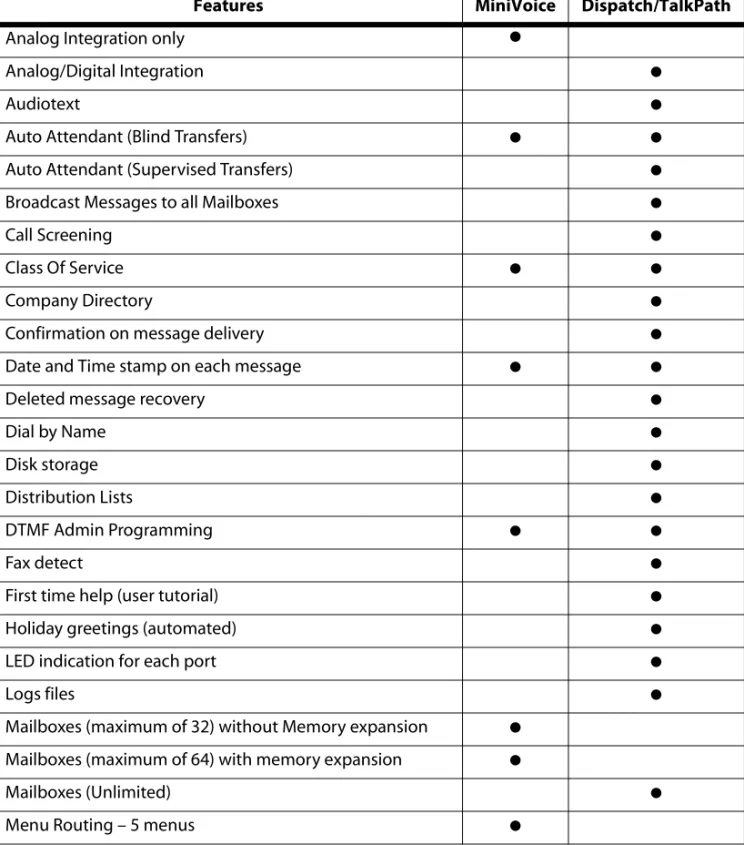
Table 1-1: Feature Comparison Chart
Features MiniVoice Dispatch/TalkPath
Analog Integration only ●
Analog/Digital Integration ●
Audiotext ●
Auto Attendant (Blind Transfers) ● ●
Auto Attendant (Supervised Transfers) ●
Broadcast Messages to all Mailboxes ●
Call Screening ●
Class Of Service ● ●
Company Directory ●
Confirmation on message delivery ●
Date and Time stamp on each message ● ●
Deleted message recovery ●
Dial by Name ●
Disk storage ●
Distribution Lists ●
DTMF Admin Programming ● ●
Fax detect ●
First time help (user tutorial) ●
Holiday greetings (automated) ●
LED indication for each port ●
Logs files ●
Mailboxes (maximum of 32) without Memory expansion ●
Mailboxes (maximum of 64) with memory expansion ●
Mailboxes (Unlimited) ●
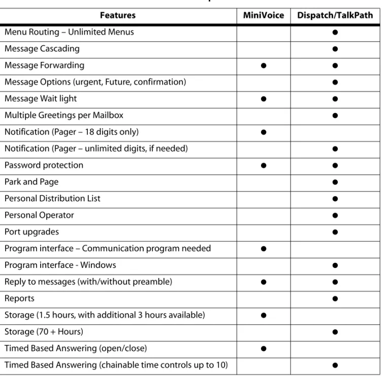
Menu Routing – Unlimited Menus ●
Message Cascading ●
Message Forwarding ● ●
Message Options (urgent, Future, confirmation) ●
Message Wait light ● ●
Multiple Greetings per Mailbox ●
Notification (Pager – 18 digits only) ●
Notification (Pager – unlimited digits, if needed) ●
Password protection ● ●
Park and Page ●
Personal Distribution List ●
Personal Operator ●
Port upgrades ●
Program interface – Communication program needed ●
Program interface - Windows ●
Reply to messages (with/without preamble) ● ●
Reports ●
Storage (1.5 hours, with additional 3 hours available) ●
Storage (70 + Hours) ●
Timed Based Answering (open/close) ●
Timed Based Answering (chainable time controls up to 10) ●
Table 1-1: Feature Comparison Chart
Installing the Voice Mail System
This section describes how to install the MiniVoice and lists the system specifications.
Box Contents
One MiniVoice
One 6’ Null Modem Cable
One Power Adapter
Six Quick Reference Cards
One System Administrator / User Manual
Connections
The MiniVoice consists of two parts - the black case with a printed circuit board and the plug-in power supply.
1. Mount the MiniVoice on a flat, dry wall surface.
2. Connect the transformer to a suitable 115-120V AC outlet.
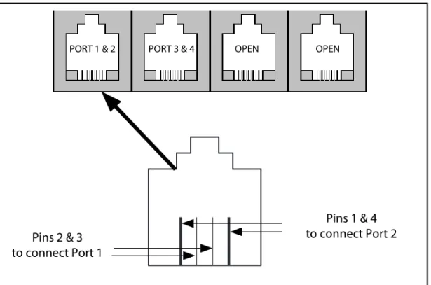
3. Connect the line cords for the analog stations being connected to the
MiniVoice from left to right in the corresponding RJ-14 jack on the bottom of the unit.
Figure 1-1: RJ-14 Pin Connections
4. Cross-connect the source jacks for these ports to the desired station port locations on the telephone system’s main distribution frame (MDF).
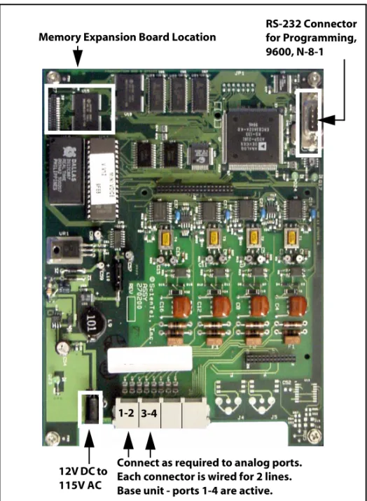
Installing the Memory Expansion Board
Refer to Figure 1-2: System Configuration Diagram to locate the proper placement for the memory expansion board.
Specifications
This table lists the MiniVoice specifications.
You must power down the system before installing memory expansion.
Table 1-2: System Specifications
Part Number Memory Total Storage Mailboxes Total Messages
703-04 Basic MiniVoice 1.5 hours 32 450
730-03 Expansion Memory 3.0 hrs 4.5 hours 64 999
PORT 1 & 2 PORT 3 & 4 OPEN OPEN
Pins 1 & 4 to connect Port 2 Pins 2 & 3
Figure 1-2: System Configuration Diagram
VM SYSTEM
Memory Expansion Board Location
1-2 3-4
Connect as required to analog ports. Each connector is wired for 2 lines. Base unit - ports 1-4 are active. 12V DC to
115V AC
RS-232 Connector for Programming, 9600, N-8-1
Voice Mail Integration Programming
DHS and DHS-E
Perform Steps 1-6 to configure the DHS with the MiniVoice system. 1. Enter System Programming as follows:
a. Connect the single line adapter box to the system (make note of the extension numbers).
b. Enter programming mode: [FEAT] + [#] + [6] + [000000]. c. Press [SHOW].
2. Enter Stations as VM ports as follows:
a. Press [NEXT] to go to the station area. Press [SHOW].
b. Enter the first station number on the keypad to be included as a VM port, then press [SHOW].
c. Press [NEXT] until the VM PORT entry is on the display. d. Press [CHG] to mark VM PORT=Y.
e. Press [HOLD] to save the entry.
f. Repeat this procedure for all stations to be entered as VM ports. g. Press [HOLD] twice to save the entries and exit to System
Programming.
3. Assign VM Type to a Station Hunt Group as follows:
a. Press [NEXT] until SYSTEM APPLICATION appears. Press [SHOW]. b. Press [SHOW] at the STATION HUNT GROUP entry.
c. Enter [1] on the keypad and press [SHOW].
d. Press [CHG] to mark the group as a VM type. Press [NEXT]. e. Press [SHOW] at the GROUP MEMBER entry.
f. Press [CHG], then enter the station number to be assigned in the group and press [SAVE].
g. Repeat the procedure until all stations are entered in the group. h. Press [HOLD] twice to save the entries and return to the STATION HUNT
4. Change In-band digits in “Voice Mail” as follows: a. Press [NEXT] to go to the Voice Mail screen. b. Press [SHOW].
c. Press [CHG] at the ICM PREFIX entry.
d. Press [FEAT], then dial [70] + [#] and press [SAVE].
Press [NEXT ] to go to the XFR PREFIX.
Press [CHG] at the VFR PREFIX entry.
Press [FEAT], then dial [70] + [6] and press [SAVE]. e. Press [NEXT] until DIS DGT appears.
f. Press [CHG], then press 666.
g. Press [SAVE], then press [HOLD] twice. 5. Change the Ring Scheme as follows:
a. Press [BACK] twice until “4 RESOURCE” appears. b. Press [SHOW].
c. Press [CHG] until “Ring Scheme” reads 1, then press [CLEAR]. 6. Assign VM Flexible Buttons at EACH Station as follows:
a. Press [FEAT] + [#] + [3].
b. Press flexible button to program. c. Press [CHG] (soft key) + [FEAT] (soft key). d. Press [FEAT] + [64]. Press [SAVE] (soft key). e. Press [CLEAR] to exit programming.
Other Vodavi Systems
Perform the following steps to configure Vodavi systems, other than the DHS, with the MiniVoice system.
1. On the single line telephone ports that are to be assigned to the VM group, disable the conference feature. Flash 50, XXX-XXX, Button #3, where XXX-XXX are the SLT extension range numbers to be assigned to the VM group.
2. Enter the VM group programming for VM group 1 (440). Flash 65, Button #1. This button should be lit for Steps 3-4.
3. Enter the single line telephone ports into a VM group (440-447). Flash 65, Button #12. Enter [1] to add or [0] to delete (FP3 or newer).
4. Enter the desired Leave and Retrieve Tables for the VM group. Flash 65, Buttons #10 and #11. Program the Leave Table as Table 0 and the Retrieve Table as Table 1.
Note that Steps 5 and 6 are accomplished in the Flash 66 programming field. These steps should be completed by default.
5. Leave Table Programming: a. Press Button #1 (Table 0).
b. Enter a [0] + [TRANS] + [6] on the keypad, where:
0 indicates a prefix digit.
The [TRANS] button represents a pause based on the system pause timer.
The 6 is used to activate a mailbox and prepare it to accept a new message.
6. Retrieve Table Programming: a. Press Button #2 (Table 1).
b. Enter a [0] + [TRANS] + [#] on the keypad, where:
0 indicates a prefix digit.
The [TRANS] button represents a pause based on the system pause timer.
# represents an owner on the VM system. c. Press the [HOLD] button to update.
d. Press Button #2 (Table 1). e. Enter [1].
f. Press the [HOLD] button to update (when you update, this field is blank). 7. Press Button #9 (disconnect table).
a. Enter [6666], where 6666 is the disconnect code used by the
MiniVoice.
b. Press the [HOLD] button to update.
8. Assign VM flexible buttons (440) on the stations. At each station perform the following:
a. Press the [SPEED] button twice.
b. Press the desired flexible button to be programmed. c. Dial [440] on the keypad.
d. Press the ON/OFF button.
Note that you can adjust the volume level on each SLT port by using the volume up or down code. This provides additional control for both internal and external calls into the voice mail system. For example, while using a single line telephone and on a CO Line call, to increase volume: perform a hook flash, then dial [638] + [8] followed by another hook flash. A
MiniVoice
Programming Devices
MiniVoice programming is accomplished by using a touch-tone telephone and a personal computer. Table 1-3 shows the categories of programming that can be performed by each device.
Table 1-3: Programming Device Comparison
Administration Telephone Computer
Class of Service ●
Date and Time ● ●
Debug ●
Free Sectors (message storage time remaining) ●
Invalid Digits ●
Mailbox Administration
Change Access Codes ● ●
Add a Mailbox ● ●
Delete a Mailbox ● ●
Record a Mailbox Greeting ●
Reset Message Wait Indication ● ●
Notification
Activate ● ●
Edit Number ●
New Number ●
Numbering Plan ●
Open and Close Schedule ●
Operating Mode
Day ● ●
Night ● ●
Automatic ● ●
Password (System) ●
PBX Integration (Telephone Type) ● ●
PBX Integration parameters ●
Record Prompts ●
Review Prompts ●
Select System Greeting / per Port
Normal ● ●
Night ● ●
Temporary ● ●
System Greeting
Review ●
Record ●
Delete ●
The following is the recommended sequence for programming the system to perform basic operations. Perform programming in the order shown in
Table 1-4 starting at the top of the table and continuing to the bottom of the table. This table illustrates the flow of programming; detailed programming steps are contained in sections titled Programming System Functions Via Computer and Programming System Functions Via Telephone.
Table 1-4: Basic Programming Using Computer Programming Programming Type Description
PBX Integration Select your telephone system from a list of possibilities. Example - selection number 00 represents Vodavi telephone systems. Open & Close Schedule Identify the hours of your business operation.
Number Plan Activate the numbers that will appear as menu selections. Mail Box Assignment Identify mailbox and extension numbers.
Activate pager/beeper notification option. Class of Service Verify COS settings.
Auto Attendant Config Verify Auto Attendant Configuration Using Telephone Programming Programming Type Description
Programming System Functions Via Telephone
To access the System Administrator Mailbox: 1. Dial into voice mail.
2. When the system answers, dial [#] followed by the System Administrator Mailbox number:
[#]+[0] = 2 digit mailbox system [#]+[00] = 3 digit mailbox system [#]+[000] = 4 digit mailbox system
The system will announce: “Mailbox 15-0”, which is the System Administrator Mailbox number. This number does not conflict with Mailbox 15 in a two-digit mailbox system.
3. When requested, enter the default System Administrator password [9]+[#]+[56].
The System Administrator Mailbox menu plays to prompt you to select one of the options listed below.
4. Select the appropriate button to select the desired option. Descriptions of the options are provided on the next several pages.
To change the System Administrator password refer to “Mailbox Administration” on page 1-18.
Press: [1] for system greetings [2] for Mailbox Administration [3] for Auto Attendant configuration [4] to set date and time
[5] to set operating mode [6] to select PBX integration [7] to record a prompt [8] to listen to a prompt
Administrator Options
System GreetingsThe programmed Day or Night greeting for each port, as programmed in the Number Plan screen, is the first announcement played to outside callers when they reach the system. Callers will either dial the system’s access number directly or they might be forwarded when the dialed extension is busy or unanswered.
You have the option to record up to nine programmable greetings to provide callers with certain information and instructions upon their entering the system.
You can customize the system sign-on greetings to meet your organization’s needs. When you record a customized greeting, remind subscribers to dial [#] to identify themselves to the system as subscribers. This is important for new subscribers who can get confused and end up leaving unintended messages for others rather than entering their own mailboxes.
Outside callers who have never encountered a voice message system should be given clear instructions on what to do when they reach the system. Since mailbox numbers are generally the same as the extension numbers, a caller can leave a message by just dialing a [6] before the extension number of their intended party. By customizing the system greeting, explicit directions can be given to the outside caller.
To program system greetings:
1. Access the System Administrator Mailbox as described on page 1-16. The System Administrator Mailbox Menu plays.
2. Press to access system greetings. The system will prompt you for the greeting number (1-9).
3. Enter the desired greeting number.
For example:
1 = Default Day greeting 2 = Default Night greeting 3 = Default Temporary greeting 4 - 9 = Open for customized greetings
4. You will be prompted with the following three choices:
Press to Review. The greeting selected in Step 3 is played, then you are returned to Step 4.
Press to Record. You will be prompted to record the greeting selected in Step 3. When you finish recording, press [#] to save the recording. Then you are returned to Step 4.
Press to Delete. The system will announce that the greeting selected in Step 3 is deleted, then you are returned to Step 4.
5. When you finish work on the greeting initially selected in Step 3, you have three choices:
Press to go back to Step 3 and select another greeting to manage.
Press to return to the Administrator Options Menu.
Press to exit the system completely.
Mailbox Administration
Mailbox administrative functions are normally accessed using the
programming terminal along with the appropriate programming screens on the system. However, for your convenience, a number of functions can be performed using your System Administrator mailbox. These include:
Changing an unknown/forgotten mailbox access code to a new temporary access code.
Adding new mailboxes. You may need to use the Mailbox Setup Screen to enter any additional information.
Deleting an existing mailbox.
Recording personal mailbox greetings.
Resetting a Message Waiting Indicator (MWI). These five activities are described in detail below.
When accessing any of these features, you are first asked to enter a mailbox number. This is the mailbox that will be acted upon.
11
12
13
16 16 16 16 16 16
Changing a Mailbox Access Code
If a subscriber forgets their access code, you can reset it without deleting the mailbox and its messages. Once they are given the new temporary access code, the subscriber should immediately enter their mailbox and change the temporary access code to one of their own.
To change a Mailbox Access Code:
1. Access the System Administrator Mailbox as described on page 1-16. The Administrator Options Menu plays.
2. Press to access mailbox administration.
3. After the prompt, enter the mailbox number for which you want to change the access code.
4. After the next prompt press to change an access code.
5. Enter the new access code, then press to accept. The system will announce the new access code for confirmation, then you are returned to the Administrator Options menu in Step 1.
6. When you finish changing the access code(s), you have three choices:
Press through to select another System Administrator task to perform.
Press to return to the system Main CCR Menu.
Press to exit the system completely.
7. Give the new temporary access code to the subscriber. Tell the subscriber to enter their mailbox immediately to change the access code to one of their own choice.
Adding a Mailbox
When you add a mailbox to the system, several default values are assigned: the extension number will be the same as the mailbox number, the password will be , the Class of Service will default to 1, and the Outcall function will be turned OFF. If you need to change these options from the default values, you will have to use the Programming Terminal.
This is the only method for changing the administrator mailbox access code.
12
11
1#
11 18 16
16 16
To add a mailbox:
1. Access the System Administrator Mailbox as described on page 1-16. The Administrator Options menu plays.
2. Press to access mailbox administration.
3. After the prompt, enter the mailbox number for which you want to add. 4. After the next prompt, press to add a mailbox. The system confirms
addition of mailbox and then returns you to the Administrator Options Menu in Step 1.
5. When you finish adding a mailbox, you have three choices:
Press through to select another System Administrator task to perform.
Press to return to the system Main CCR Menu.
Press to exit the system completely. Deleting a Mailbox
To delete a mailbox:
1. Access the System Administrator Mailbox as described on page 1-16. The Administrator Options menu plays.
2. Press to access mailbox administration.
3. After the prompt, enter the mailbox number for which you want to delete.
4. After the next prompt, press to delete the mailbox.
5. After the prompt, press to confirm deletion or to cancel. You are then returned to the Administrator Options Menu in Step 1.
6. When you finish mailbox deletion activities, you have three choices:
Press through to select another System Administrator task to perform.
Press to return to the system Main CCR Menu.
Press to exit the system completely.
Deleting a mailbox is a permanent action and the mailbox or its messages cannot be recovered after the delete action is confirmed by pressing .
12
12
11 18 16
16 16
1#
12
13
1# 16
11 18 16
Recording a Mailbox Greeting
You can use the System Administrator’s Mailbox to record the mailbox greeting for any system mailbox.
To record a mailbox greeting:
1. Access the System Administrator Mailbox as described on page 1-16. The Administrator Options menu plays.
2. Press to access mailbox administration.
3. After the prompt, enter the mailbox number for which you want to record a greeting.
4. After the next prompt, press to record a mailbox greeting. 5. After the beep, record the mailbox greeting, then press when
finished.
6. After the prompt, press to confirm the recording is satisfactory. You are then returned to the Administrator Options Menu in Step 1.
7. When you finish recording mailbox greeting activities, you have three choices:
Press through to select another System Administrator task to perform.
Press to return to the system Main CCR Menu.
Press to exit the system completely.
Resetting a Message Waiting Indicator
The System Administrator can reset the message waiting indicator (MWI) for a mailbox. When this option is selected, the system checks the current status of any messages stored in the mailbox. The system then dials the appropriate MWI “turn on” code if there are new messages in the mailbox and the appropriate “turn off” code if there are no new messages in the mailbox. This operation will re-synchronize the physical MWI with the mailbox message status.
To reset an MWI:
1. Access the System Administrator Mailbox as described on page 1-16. The Administrator Options menu plays.
2. Press to access mailbox administration.
12
14
1# 1#
11 18 16
16 16
3. After the prompt, enter the mailbox number for which you need to reset the MWI.
4. After the next prompt, press to reset MWI. The system confirms that the request has been processed and you are returned to the Administrator Options Menu in Step 1.
5. When you finish resetting MWI activities, you have three choices:
Press through to select another System Administrator task to perform.
Press to return to the system Main CCR Menu.
Press to exit the system completely.
Auto Attendant Configuration
Using this option allows you to easily change the greeting a caller will hear on a given port between the programmed Day/Night greeting and the
programmed Temporary greeting. This is useful when a Temporary greeting for something like a weather-related closing needs to be activated from a remote location.
To change the Auto Attendant Configuration:
1. Access the System Administrator Mailbox as described on page 1-16. The Administrator Options menu plays.
2. Press for Auto Attendant Configuration.
3. After the prompt, press to select normal greeting or press to select temporary greeting.
4. After the prompt, press the appropriate port number to change - . You are returned to the Administrator Options Menu in Step 1.
5. you are returned to the Administrator Options Menu in Step 1.
6. When you finish Auto Attendant Configuration activities, you have three choices:
Press through to select another System Administrator task to perform.
Press to return to the system Main CCR Menu.
Press to exit the system completely.
15
11 18 16
16 16
13
11 12
11 14
11 18 16
Setting Date and Time
You may use the System Administrator Mailbox to set the system date and time. The time and date stamp is used for all envelope information and to check delivery notifications. It is important to set the system date and time accurately.
To set the system date and time:
1. Access the System Administrator Mailbox as described on page 1-16. The Administrator Options menu plays.
2. Press to Set Date and Time. 3. After the prompt, press:
to review data - the current date and time settings in the Voice Mail are announced, then you are returned to the Administrator Options Menu.
to change data - after the first prompt, enter the time in four-digit military time format e.g., 0930 for 9:30 a.m. or 1830 for 6:30 p.m. After the second prompt, enter the date as a six-digit number in MMDDYY format. You are then returned to the prompt that asks if you want to review data, change data, or exit.
to exit - you are returned to the Administrator Options Menu. 4. When you finish setting Date and Time activities, you have three choices:
Press through to select another System Administrator task to perform.
Press to return to the system Main CCR Menu.
Press to exit the system completely.
The time and date must be reset whenever there is a local time change such as Daylight Savings Time.
14
11
12
16
11 18 16
Setting Operating Mode
Under normal conditions, the pre-programmed Auto Attendant screen controls the greeting that plays when MiniVoice answers a caller. This screen tells MiniVoice which greeting to play based upon the time of day, Day or Night, which is programmed in the Open & Close screen.
There may be a time when it is desirable to change the system from Day (Mode 1) to Night (Mode 2) at an other-than-normal time. The System Administrator can accomplish this by dialing into the system, rather than having to access the programming terminal.
The following are the System Operating Mode Numbers and their meanings.
Mode 1 - Fixed Day Mode: the system is in Day Mode all of the time.
Mode 2 - Fixed Night Mode: the system is in Night Mode all of the time.
Mode 3 - Automatic Mode: the system follows the Open & Close times as programmed.
When the mode is changed manually to either Mode 1 or Mode 2, MiniVoice
stays in that mode until the System Administrator changes the mode back to Automatic mode through the Administration Options menu. The mode cannot be changed from the programming terminal.
To change the Operating Mode:
1. Access the System Administrator Mailbox as described on page 1-16. The Administrator Options menu plays.
2. Press to Set Operating Mode. 3. After the prompt, press:
to review data - the system will announce the current Mode and then you are returned to the prompt that asks if you want to review data, change data, or exit.
to change data - after the prompt, press:
for Day Mode - choice is confirmed, then you return to prompt asking if you want to review, change, or exit.
for Night Mode - choice is confirmed, then you return to prompt asking if you want to review, change, or exit.
for Automatic Mode - choice is confirmed, then you return to prompt asking if you want to review, change, or exit.
to exit - you are returned to the Administrator Options Menu. 4. When you finish Setting the Operating Mode, you have three choices:
Press through to select another System Administrator task to perform.
Press to return to the system Main CCR Menu.
Press to exit the system completely.
15 11 12 11 12 13 16
11 18 16
Selecting PBX Integration
MiniVoice uses a set of pre-programmed PBX Integration screens. These screens provide standard configurations for various PBX systems that might be used with MiniVoice.
The current PBX Integration may be changed from the System Administrator Mailbox.
To change the PBX Integration:
1. Access the System Administrator Mailbox as described on page 1-16. The Administrator Options menu plays.
2. Press to Select PBX Integration. 3. After the prompt, press:
to review data - the system will announce the current PBX
Integration and then you are returned to the prompt that asks if you want to review data, change data, or exit.
to change data - after the prompt, enter the desired two-digit Integration Number. You are then returned to the prompt that asks if you want to review data, change data, or exit.
to exit - you are returned to the Administrator Options Menu. 4. When you finish Selecting a PBX Integration, you have three choices:
Press through to select another System Administrator task to perform.
Press to return to the system Main CCR Menu.
Press to exit the system completely.
16
11
12
16
11 18 16
Recording a Prompt
MiniVoice is shipped with a complete set of system voice prompts. These system prompts cover all system operations and functions.
There may be occasions, however, when it is desired to change the wording of a prompt to meet a specific requirement. This function allows such changes.
Refer to “Voice Prompts” on page 1-58for a complete listing of the system’s default voice prompts.
To re-record a System Prompt:
1. Access the System Administrator Mailbox as described on page 1-16. The Administrator Options menu plays.
2. Press to Record a Prompt.
3. After the prompt, enter the three-digit prompt number of the prompt that you want to re-record.
4. After the beep, record your new prompt, then press when finished recording. You are then returned to the Administrator Options Menu. 5. When you finish Recording a Prompt, you have three choices:
Press through to select another System Administrator task to perform.
Press to return to the system Main CCR Menu.
Press to exit the system completely.
All of the supplied prompts are the same voice and volume level. If you desire to re-record a prompt, you should ensure that you use the same volume level and a similar tonal quality as the original.
You must not change any of the listed options and their activation keys. If you do, you will become confused when the options do not work as expected. There is no way to change these options in the field.
17
1#
11 18 16
Listening to a Prompt
MiniVoice includes a method of listening to any or all of the recorded prompts. This may be used to determine whether it is necessary to modify a prompt.
You can listen to a single prompt, a range of prompts, or the last prompt that was recorded.
To listen to System Prompts:
1. Access the System Administrator Mailbox as described on page 1-16. The Administrator Options Menu plays.
2. Press to Listen to a Prompt.
3. After the prompt, enter one of the following options:
A three-digit prompt number, then when prompted enter the same number a second time. The selected prompt plays and then you are returned to the Administrator Options Menu.
-or- The first three-digit number of the range followed by the second three-digit number of the range. The selected prompts play and then you are then returned to the prompt that asks if you want to listen to a single prompt, listen to a range of prompts, or listen to the last prompt recorded.
-or- Press to listen to the last prompt recorded. After the prompt plays you are returned to the Administrator Options Menu. 4. When you finish Listening to Prompts, you have three choices:
Press through to select another System Administrator task to perform.
Press to return to the system Main CCR Menu.
Press to exit the system completely.
18
1#
11 18 16
Programming System Functions Via Computer
PC Accessibility
Cable Connection -- The cable between the MiniVoice unit and the PC must be a NULL MODEM arrangement with a 9-pin female connector on each end.
Lift the cover of the unit to access the programming port.
After connecting the cable to the PC, plug the other end into the programming port on the MiniVoice unit.
Desktop or Laptop -- Programming is accomplished through the use of a laptop or standard PC desktop system. No special software is required. Any communications package that supports ANSI terminal emulation will work. The required port speed and protocol is 9600 BAUD, N-8-1.
If HyperTerminal is the communications package to be used, perform the following steps before programming:
1. Select Start > Programs > Accessories > Communications > HyperTerminal.
2. Setup a new connection using the following settings:
a. Select COM1 or COM2, as required by your PC, then press OK
b. On the Comport Settings screen, set 9600, N 8 1, Flow Control to XON, XOFF.
c. Click OK.
d. Click on File > Properties, then select the Settings tab. e. Select Auto Detect as the emulation.
f. Click on the ASCII setup button and uncheck the “Wrap lines that exceed terminal width” option.
g. Click OK, then click OK again.
3. The HyperTerminal connection is now configured properly for programming the MiniVoice.
4. Exit HyperTerminal, then re-start the program.
5. After connected to the MiniVoice, press ESC to access the Main Programming Menu.
Navigating in the System
Programming the MiniVoice requires that you make entries in specific fields on several programming screens.
These screens are accessed from the main menu by selecting a number and pressing the <ENTER> key.
While working on a particular screen, use the arrow keys or the <ENTER> key to move through the fields. After you change a given field, press the <ENTER> key to save your change.
If you are working in an area with multiple pages, such as the mailbox screen, press <F1> to go forward 1 screen and <F2> to go back 1 screen.
When you finish work on a particular screen, press the <ESC> key to return to the Programming Menu.
When you finish programming, type exit and press the <ENTER> key to shut down the programming interface.
Access to the MiniVoice is protected by password to prevent unauthorized changes to voice mail system parameters.
(The voice mail password must be re-entered each time you access the Programming area.)
Menu Option Screens
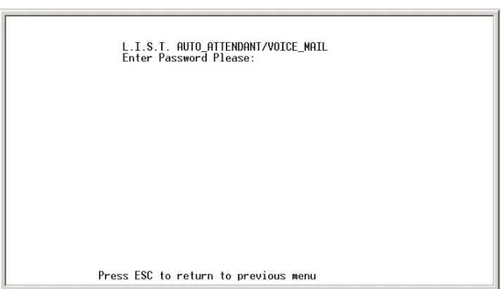
Signing On
This is the screen first shown when the programming terminal is connected. The default factory password is 0000. It can be changed by selecting Option 8 on the Programming Menu.
Figure 1-3: Sign-On Screen
To enter the programming area, type in the correct password, then press <ENTER>.
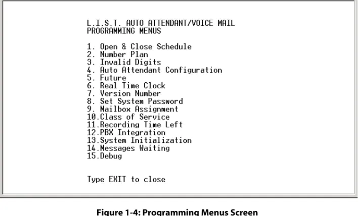
Programming Menus
The programming functions available are shown in Figure 1-4 . Each function shown in the Programming Menus screen is linked to another screen where its parameters can be set. Each screen is described on the following pages.
Figure 1-4: Programming Menus Screen
1. To go to a specific screen, use the arrow keys to scroll down to your choice,
-or-Type in the desired menu choice number. 2. Press the <ENTER> key to go to that screen.
Open and Close Schedule
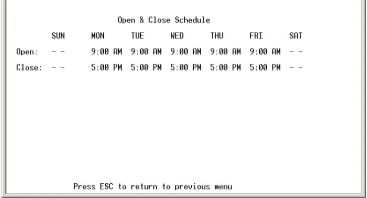
This time control screen is used to set the time when the MiniVoice switches from Day to Night mode or Night to Day mode. Separate greetings are available for each mode. The greetings introduce callers to your company and tell them what digits to press to access certain departments, extensions, mailboxes, etc.
The Day/Opening greeting plays from the time you specify in the Open field until the time specified in the Close field. The Night/Close greeting plays after the time specified in the Close field until the next specified time in the Open field. For example, in Figure 1-5 the Day greeting is played during weekdays from 9:00 a.m. through 5:00 p.m. The Night greeting is played from 5:00 p.m. through 9:00 a.m. Monday through Friday, and from 5:00 p.m. Friday through 9:00 a.m. Monday
Figure 1-5: Open & Close Schedule Screen
1. Enter the desired time schedule for each day as required. For example, Open: 9:00 AM, Close: 5:00 PM.
2. Press <ENTER> to store each entry.
To delete an entry:
1. Press the arrow key until the desired field is selected. 2. Then press <F4>.
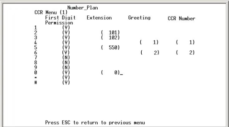
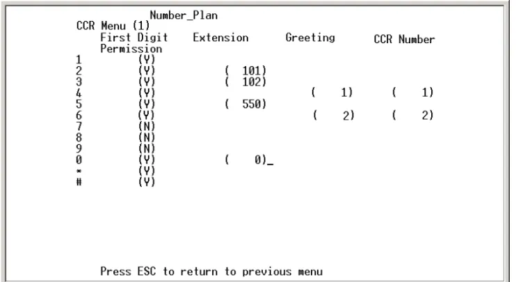
System Numbering Plan
This menu screen is used to control how the MiniVoice system processes digits entered by a caller.
Figure 1-6: Number Plan Screen
Leaving the Open and Close entries blank for a given day will represent a 24-hour period.
Entries can be made using 24-hour notation, e.g., 18:00 represents 6:00 p.m.
If you use the F4 key to clear all of the times, the system will continue to use the greeting that was active at the time that you cleared the entries.
Field Description
FIRST DIGIT PERMISSION
This field tells the system whether a given digit is allowed to process additional digits. For example:
If your extension numbers start with 1, this field will contain a Y and other fields to its right will be blank. When a caller dials a 1, the system knows additional digits will follow and be acted on (Figure 1-6).
If this field contains a Y, the system will check the following fields and perform the actions designated in these fields:
EXTENSION -- dials the extension number specified and connects the caller. GREETING -- plays the specified greeting to the caller.
CCR -- takes the caller to the specified one of five possible pre-programmed routing menus and plays the greeting for that menu.
If the field contains an N, the system will tell the caller that they have dialed an incorrect digit and they will be allowed to dial again.
EXTENSION This field may contain any valid extension number as the destination. For example, for Sales press [2]. extension 101 is dialed, and the caller is connected to Sales (Figure 1-6). GREETING This field contains the greeting number to be played when this digit is dialed. Active
greeting numbers are 01- 09 and they are recorded via telephone programming. An entry in the Greeting field requires an associated entry in the CCR Number field, even if the CCR Number is the same as the CCR Menu from which you are configuring
CCR Custom Call Routing (CCR). This field may contain a CCR menu number of 1-5 that links a to an additional number plan when the caller presses the digit in the left column. Up to five number plans can be used (Figure 1-8). CCR numbers can also be tiered, as described by the second example below. To access CCR menus for configuration, press F1 to increment ascending from CCR 1-5 or press F2 to increment descending from CCR 5-1.
For example:
A CCR Menu 1 entry of 2 in the CCR field could link to a number plan for Sales, 3 for Tech Support, 4 for Services, and 5 for Repairs. Figure 1-9 graphically portrays this example.
A CCR Menu 1 entry of 2 in the CCR field will link to CCR Menu 2 number plan (Sales). Sales can be subdivided into In-State and Out-of-State sales making two entries (3 & 4) in the CCR field of CCR Menu 2. Figure1-10 graphically portrays this example.
Dual-action keys have a 3-second pause prior to switching to another CCR. For example, you are prompted to dial an extension (100 series) or press 1 for Sales. After pressing [1], the system pauses until either additional digits are entered for an extension or 3 seconds elapse, whichever occurs first.
The example in Figure 1-7 shows that when the number 1 and additional digits of an extension are dialed, the call will be transferred to that extension. For example, if 108 is dialed, the call will transfer to extension 108. If the numbers 2, 3, or 5 are dialed, the caller will go directly to the corresponding extension or UCD/ACD group (101, 102, or 550). If number 4 is dialed, greeting 1 will be played to the caller. If number 6 is dialed, the caller will be linked to the CCR Menu 2 number plan. The system administrator has designated numbers 7, 8, and 9 as invalid numbers in this example.
Figure 1-9: CCR Menus Example
Figure 1-10: CCR Menu Tiering Example
Sales
Repairs Tech Support Services
CCR MENU 4
CCR MENU 5 CCR MENU 2
CCR MENU 1
CCR MENU 3
Out-of-State Company X
Sales
In-State
Invalid Digits
This screen is used to instruct the MiniVoice to ignore certain digits that may be dialed. When these digits are encountered, they are ignored.
Auto Attendant Configuration
This “Voice Lines” screen is used to control what a caller will hear when a given port answers. Each port may play a different greeting.
Figure 1-12: Auto Attendant Screen
Each column in Figure 1-12 represents a given port from 1 to 4. The fields in each column are explained below.
Field Description
OPRERATOR EXT This is the extension number of the Operator’s extension for this port. When a caller dials [0], this is the destination extension.
HUNT Future option - not currently active VMS Future option - not currently active
Field Description
DAY MODE
GREETING NO. The greeting number (01-09) that plays when this port is accessed during the day hours, as defined in the Open & Close Schedule.
DAY MODE CCR
The number (01-05) identifying the CCR menu that answers during the day hours, as defined in the Open & Close Schedule.
NIGHT MODE
GREETING NO. The greeting number (01-09) that plays when this port is accessed during the night hours, as defined in the Open & Close Schedule.
NITE MODE CCR
The number (01-05) identifying the CCR menu that answers during the night hours, as defined in the Open & Close Schedule.
TEMP GRT ON If this field is set to Y, the programmed TEMP GREETING message will be played to a caller.
If this field is set to N, the programmed GREETING NO. message will be played. This message may be changed from any telephone - internal or external. TEMP GREETING If Temp Greeting is active (Y), this is the greeting that plays when this port answers. NOANSGREETING Future option - not currently active
AUTOATT START If this option is set to Y, the system goes off-hook on an incoming call and waits for integration digits.
NOTE -- This is the default setting and it should not be changed unless necessary.
If this option is set to N, the system goes off-hook on an incoming call and immediately plays the programmed greeting according to the Open & Close Schedule, but does not respond to DTMF tones.
System Clock Adjustments
This screen is used to adjust the Real Time Clock settings of the MiniVoice. Use the arrow keys to navigate left and right, then make the desired changes.
Figure 1-13: Date & Time Screen
To enter a new date and time:
1. Enter a value of 1-7 to identify the day of the week. 1 = Sunday 5 = Thursday
2 = Monday 6 = Friday 3 = Tuesday 7 = Saturday 4 = Wednesday
2. Press the right arrow key or press the <ENTER> key. 3. Enter a value of 1-12 to indicate the month.
4. Press the right arrow key or press the <ENTER> key. 5. Enter a four-digit value to indicate the year.
7. Enter a value of 1-24 to set the hour field. Use military 24-hour format to set the Time.
8. Press the right arrow key or press the <ENTER> key. 9. Enter a value of 0-59 to set the minutes field.
Example -- To set the time to 6PM, enter 18:00. The voice mail system will automatically convert the military time to standard time notation when the changes are saved.
Any or all settings may be changed at the same time.
10. When you finish making changes, press the <ENTER> key to save the new settings.
Version Number
This choice will display the current Software version number. This information is useful when speaking with technical support personnel.
You can press the <Enter> key after each value entered. A shortcut is to enter a string of values separated by a <space> between each value, then pressing <Enter>. For example: an entry of 2 <space> 3 <space> 18 <space> 2001 <space> 18 <space> 30 <Enter>, will represent Monday, March 18, 2001, 6:30 p.m.
Set System Password
This screen is used to change the system password. If you wish to change the voice mail system password from the default value of 0000, enter the new password here. (The password MUST be four digits.)
The new password takes effect next time you access programming menus.
Mailbox Assignment
This screen controls mailbox user options. There are a total of 64 mailboxes available in the MiniVoice. Each mailbox may be assigned any of the four available Classes of Service, and be allowed or denied the ability to make outcalls to a beeper. A description of the fields on the mailbox assignment screen are provided below.
Figure 1-15: Mailbox Assignment Screen
Field Description
MAILBOX - NO - EXT
This heading contain two fields:
Mailbox index number (1-64). This is generated automatically by the system.
Mailbox number that relates to the physical extension number. Example, 100-163. ACCESS CODE Password designated by the mailbox owner for accessing the mailbox.
Field Description
EXT NO Number of the physical extension for this mailbox.
This is the station that will be the destination of callers when transferred by the voice mail system.
It is also the number used when activating or deactivating MWI indicators. CLASS OF SERVICE Number of the assigned Class of Service as programmed in Class of Service screen. DIAL OUT Controls whether a given mailbox is allowed to make outcalls to a beeper/pager BEEPER NO Allows beeper outcalls.
Only enter the beeper/pager telephone number.
The system will verify the outdial access code entered on the PBX Integration Screen.
MSG IND Shows the current status of the telephone MWI indicator according to the system.
0 = OFF
1 = ON
When the integration type is changed on screen 12, MiniVoice will automatically insert the correct mailboxes into this screen as a default condition.
When there are more mailboxes than appear on the screen, press [F1] to go forward 1 screen and [F2] to go back 1 screen.
Adding a Mailbox
From the Main Menu:
1. Press <9> to enter Mailbox Assignments.
2. Move the cursor to the first available line, at a position left of the index number field. Press [F1] to go to the next page, if necessary.
3. Enter in order:
a. Next index number, then space.
b. Mailbox extension number, then space.
c. Access code if available, otherwise 0000 (valid codes are 0000-9999), then space.
d. Extension number to be associated with this mailbox (this must be the same number as the mailbox number).
e. Press <ENTER>. To continue adding mailboxes, return to step 3a. 4. After you finish adding mailboxes, press <ESC> to save your changes and
return to the Programming Menu.
An example of a valid entry is: [32] + space + [100] + space + [0000] + space + [100] + <ENTER> + <ESC>
A system can use 2-digit, 3-digit, or 4-digit mailbox numbers. However, a system cannot number mailboxes using a combination of 2, 3, and 4-digit lengths. For example, if 2-digit numbering is used, then all mailboxes must be numbered with 2 digits.
When adding a mailbox, the Class of Service field automatically updates to a default value of 1 and the Dial Beeper No Out field automatically updates to Off. After the mailbox is established, these fields and the beeper/pager No can be modified as desired.
If an invalid beeper/pager number is entered, a user cannot activate this type of notification remotely.
Mailbox Capability Only
Not all employees have “traditional” offices, so they do not have telephones on the system and a call doesn’t need to be transferred to an extension. The call goes directly to a mailbox. To program this, arrow over to the mailbox, then press [F4]. This deletes the extension number and leaves only a mailbox. Mailbox extension numbers 104/105 in Figure 1-16 are examples.
Figure 1-16: Mailbox Only
An abbreviated entry is possible if both the mailbox number and the extension number are identical. In this case, enter the index number, space, mailbox number, and then press <ENTER>. The MiniVoice will automatically apply all other required entries.
Deleting a Mailbox
From the Programming Menu:
1. Press <9> to enter Mailbox Assignments.
2. Move the cursor bar down to the mailbox that is to be deleted. 3. Press <F4> to delete the mailbox.
4. Press <Y> to confirm delete.
5. When you finish, press <ESC> to save your changes and return to the Programming Menu.
Class of Service
The MiniVoice provides four Classes of Service. Each COS has three parameters that may be specified:
Recording Time Left
This screen is used to display the amount of voice storage space that is currently available in the MiniVoice. The memory expansion increases the storage space by 180 minutes.
Figure 1-18: Free Sectors Screen
Field Description
SAVE PERIOD IN DAYS
Specifies the number of days that a message is retained before being automatically deleted. No warning is given before the message is deleted. It is important to delete messages so that the storage space is not completely consumed.
LENGTH OF MSG IN MINUTES
Controls the allowable recorded length of a message that may be left in a user’s mailbox.
NUMBER OF MESSAGES
Controls the total number of messages that a given mailbox user may have in their mailbox at any one time. The mailbox will indicate that it is full, once this count is matched. For example, if set to 5, the 6th caller receives a message “I’m sorry, the mailbox is full”.
PBX Integration
The MiniVoice provides several pre-programmed integration modules for the most popular telephone systems.
Figure 1-19: PBX Integration Screen
Selecting a Telephone System -- Use the arrow keys to scroll to the desired name or type the number corresponding to the selection, then press the <ENTER> key. Your selection is displayed in the Screen in Effect field.
For example, if you scroll to 00 for Vodavi phone systems and press <ENTER>, the Screen In Effect field displays 00.
Changing a Parameter -- In cases where you need to change a parameter used by the PBX integration screen, perform the following steps:
1. Use the arrow keys to scroll to select your PBX integration, then press the <ENTER> key.
2. Press the <ENTER> key a second time to display the next PBX Integration Screen.
PBX Integration Programming - (Sub Menu)
A description of the fields of the PBX integration screen is provided below.
Figure 1-20: PBX Integration Screen (continued)
Changing from one PBX integration to another will wipeout all of the existing mailboxes and there is no way to recover them.
Field Description
PBX CODE Number the system uses to determine which PBX screen to reference for system parameters.
Example -- If 00 is selected as the PBX Integration, the system will use the entries located on screen 00 to determine integration patterns, MWI on & off codes, etc.
NAME Descriptive name used to visually identify the particular Integration Screen. This name is the one displayed in the PBX Integration Selection Menu.
Field Description
MWI CODE ON Code the system sends when a mailbox has a new message.
This code tells the telephone system to activate the MWI indicator for that mailbox’s extension.
When entering the code, the colon character “:” represents the extension number. Example -- If your MWI On code is 420 followed by the extension number, enter the following sequence: ,420:,
It is recommended to always end the sequence with a comma (1-second pause) to allow the telephone system enough time to accept the command.
MWI CODE OFF Code the system sends when a mailbox user has checked all new messages.
This code tells the telephone system to deactivate the MWI indicator for that mailbox’s extension.
When entering the code, the character “:” represents the extension number. Example -- If your MWI Off code is 421 followed by the extension number, enter the following sequence: ,421:,
It is recommended to always end the sequence with a comma (1 second pause) to allow the telephone system enough time to accept the command.
MWI/OUTDIAL
PORT CONTROL Digit position tells the system which ports are allowed to make outdials.The first 4 positions correspond to ports 1 through 4 - from left to right. The last four digit positions must contain zeroes.
Default = 00030000. (This tells the system to use port 4 to make all outdial calls.) MAIL BOX
LENGTH Tells the system how many digits are required for the mailbox numbers used in the system. The default is 3 digits. The setting is changeable between 2-4 digits. TRANSFER
SEQUENCE Dialing pattern the system uses to transfer a caller from the Auto Attendant to a mailbox user’s telephone. (Default = T&) INTERNAL
CALL PREFIX System dials prefix to access internal dial tone. (This field is normally blank since most telephone systems supply dial tone when the port is taken off-hook to dial.) RECONNECT
Field Description
MINIMUM
ON-HOOK DELAY Period of time that a port will wait after hanging up before attempting to use that port for an outdial operation.
This prevents collisions when a new call appears at the port right after it has released a previous caller.
If no new incoming call is detected before this timer expires, the outdial request will be processed.
OUTDIAL
CALL PREFIX Dialing pattern used to tell the PBX an outside line is needed, such as during an outdial operation. Default = 9. If your trunk access code is different, change this value as required. HANG-UP CODE Most PBX systems are either programmed or automatically send a disconnect code.
When the PBX port is about to close (EX: an outside caller has hung up) a digit string is sent to the voice mail system.
If this string matches the entry in this field, the system saves any messages being recorded and then the port closes and waits for the next call.
FIRST DIGIT
TIME-OUT When receiving an incoming call: This is the time that the system waits to see if DTMF integration strings are being sent to the system.
If no digits are received during this period, the system will then play the main greeting for that port and be ready to accept caller-dialed digits. (Default value = 20, which represents 2000 ms or 2 seconds)
LAST DIGIT
TIME-OUT When the system receives DTMF integration strings: This is the period of time to wait after each digit to determine if more digits are coming.
As each digit is received, this timer is re-started.
Once this timer expires, the system assumes that all DTMF integration digits have been received.
The received string is then analyzed to determine how the call must be processed. DIRECT VOICE
MAIL ACCESS This is the digit that allows a caller to bypass the recorded greetings and go directly to a mailbox user’s greeting. PROTOCOL AREA
(DTMF / ACTION) Area has two fields. Values are matched pairs: a DTMF Protocol and an Action to take if that protocol is found.
All protocol entries are compared in sequence to the inbound DTMF digits until a match is found.
If no match is found, the call is directed to the main greeting for that port. - DTMF
PROTOCOL The pattern is matched against the incoming DTMF string for all call processing. After the correct pattern has been matched, then the corresponding action is taken e.g.,Protocol pattern MMM represents 3 digits.
Field Description
- ACTION TAKEMSG ENTERMB VCMAIL_ACC IGNORE
Once a matching DTMF protocol is found, the Action column tells the system what to do with that particular call. The allowable actions are:
Take a message into the requested mailbox.
Open the requested mailbox, ask caller for password.
Take no action when this DTMF protocol is received. PROTOCOL ENTRY
ORDER This is the order of integration information as the telephone system sends it to the voice mail port. Integration Examples
Example 1 -- System answers a call and receives a three-digit extension number: 104 … The system receives an entry for MMM. The Action for this protocol is TakeMsg. Once the match is made, the system opens mailbox 104, plays the mailbox greeting to the caller and records the message.
Example 2 -- System answers a call and receives a code followed by a 3-digit extension number: [6] 104 …
The system receives an entry for [6]MMM. The Action for this protocol is TakeMsg. Once the match is made, the system opens mailbox 104, plays the mailbox greeting to the caller and records the message.
Example 3 -- System answers a call and receives a code followed by a 3-digit extension number: [#] 104 …
The system receives an entry for #MMM. The Action for this protocol is EnterMB. Once the match is made, the system opens mailbox 104, plays the mailbox name to the caller and asks for their password.
System Initialization
Enter [Y] to initialize the voice mail system and erase all messages. Enter [N] or press [Esc] to exit this option without initializing the voice mail system.
Messages Waiting Display
This screen displays how many new messages are waiting in the voice mail system and the mailboxes that own them.
If a line has multiple mailbox numbers, this indicates that the message has been copied to other mailboxes.
As mailbox owners listen to their messages and delete them, their numbers will be removed from the screen.
Figure 1-21: Messages Waiting Screen
Debug Information Screen
This screen shows various trouble-shooting information fields. They will usually be used in conjunction with a Vodavi technician when trying to identify a problem that may be occurring.
This screen is accessible only when the Dealer Password is used to enter System Programming. Contact Technical Support for details.
Voice Prompts
The following table provides a listing of the default voice prompts that the system contains.
Table 1-5: Voice Prompts (Defaults) Number Prompt
001 Hello, Please enter the extension number of the person that you are trying to reach. To reach an Operator, press 0.
002 Enter your mailbox number
003 I am sorry, there is no such mailbox number 004 Enter your password
005 Invalid password
006 Mailbox menu…To review your messages, press 1; Send a message, press 2; Mailbox options, press 3
007 You have entered an incorrect digit
008 If you are satisfied with this message, press #…; to review, press1; re-record, press 2; append, press 3; to cancel, press *
009 To replay the message, press 1…; to save this message, press 2; delete it, press 3; reply, press 5; to send a copy, press 6; for message information, press 8
010 NO CURRENT PROMPT
011 Record a message at the tone, when you have finished, press # 012 To activate…
013 Mailbox options…Greetings, press 1; Password, press 2; Outcall notification, press 3 014 Hanging up now…goodbye
015 Message deleted
016 To confirm deletion of this message, press #, to cancel, press * 017 To copy with comments, press 1, to copy without comments, press 2 018 Enter destination number
019 The mailbox is not empty 020 The system is full
021 Enter a new password 022 Press 1
023 No
025 new 026 and 027 saved 028 message 029 messages 030 Zero 031 One 032 Two 033 Three 034 Four 035 Five 036 Six 037 Seven 038 Eight 039 Nine 040 Ten 041 Eleven 042 Twelve 043 Thirteen 044 Fourteen 045 Fifteen 046 Sixteen 047 Seventeen 048 Eighteen 049 Nineteen 050 Twenty 051 Thirty 052 Forty 053 Fifty 054 Sixty 055 Seventy 056 Eighty 057 Ninety
Table 1-5: Voice Prompts (Defaults) Number Prompt
058 1999
059 Two thousand
060 Message from
061 Mailbox
062 Message sent 063 an outside party
064 Sunday 065 Monday 066 Tuesday 067 Wednesday 068 Thursday 069 Friday 070 Saturday 071 January 072 February 073 March 074 April 075 May 076 June 077 July 078 August 079 September 080 October 081 November 082 December 083 AM 084 PM
085 Press 1 to change an access code, 2 to add a mailbox, 3 to delete a mailbox, 4 to record a mailbox greeting, 5 to reset MWI
086 Make your selection now 087 Dial system greeting
088 This message is too short, please record a longer message 089 Outcall notification is active
Table 1-5: Voice Prompts (Defaults) Number Prompt
090 Outcall notification is deactivated
091 If you have a mailbox on this system, press # 092 Message delivered
093 Message saved 094 Message deleted
095 To send your message now, press #, to cancel, press *
096 * if there are no other recipients or enter next recipient’s mailbox number now 097 I am sorry you are experiencing difficulties
098 First message 099 Next message 100 First saved message
101 You have entered too few digits
102 Password
103 At the tone, record your message, when you have finished recording, press #
104 System prompt review: To listen to one prompt enter the three digit prompt number twice; To listen to a range of prompts, enter the ranges’ first three digit prompt number followed by the second three digit prompt number; To listen to the prompt that was recorded last press the # key.
105 Please enter your three digit number
106 Enter the extension number of the party you are calling 107 - 0.7 seconds of silence - (NO RECORDING NEEDED HERE) 108 That mailbox is full and cannot accept any new messages 109 Remaining recording time is sixty seconds
110 You have no messages in your mailbox 111 Please hold, while I transfer your call 112 Press any key to continue
113 Greetings…Review, press 1; Record, press 2; Delete, press 3
114 To review your name, press 1; mailbox greeting, press 2; temporary greeting press 3 115 To record your name, press 1; mailbox greeting, press 2; temporary greeting press 3 116 To delete your name, press 1; mailbox greeting, press 2; temporary greeting press 3 117 Greeting has not been recorded
118 Name has not been recorded
119 Temporary greeting has not been recorded 120 Greeting was deleted
Table 1-5: Voice Prompts (Defaults) Number Prompt