T E KLYNX
LABELVIEW
V E R S I O N
8
Q
U
I
C
K
S
T
A
R
T
G
U
I
D
E
Quick Start Guide
Supply of the software described in this manual is subject to a
user license. The software may not be used, copied or
reproduced on any medium whatsoever, except in accordance
with this license.
No portion of this manual may be copied, reproduced or
transmitted by any means whatsoever, for purposes other than
the personal use of the buyer, unless written permission is
obtained from Teklynx Newco SAS.
© 2011 Teklynx Newco SAS.
All rights reserved.
TEKLYNX and its products are trademarks or registered
trademarks of Teklynx Newco SAS. All other brands and
product names are the trademarks of their respective owners.
Rev – 200511
Table of Contents
About this Manual . . . iii Chapter 1: Getting Started . . . 1-1
Starting the Program . . . 1-1 Exploring the Main Window . . . 1-1 Menu Bar . . . 1-1 Style Bar . . . 1-2 Drawtools Bar . . . 1-4 Options Bar . . . 1-5 Server Bar . . . 1-6 Float Bar . . . 1-7 Status Bar . . . 1-8 Rulers . . . 1-8 Rotation Button . . . 1-8 Design Area Display Settings . . . 1-8 Printer Setup . . . 1-9 Selecting a Driver for Printing Labels . . . 1-9 Removing a Printer . . . .1-11
Chapter 2: Data Sources. . . 2-1
What is a Data Source?. . . 2-1 Types of Data Sources . . . 2-2
Chapter 3: Designing Labels. . . 3-1
Creating a New Label . . . 3-1 Opening an Existing Label . . . 3-2 Adding Objects to the Label. . . 3-3 Adding Text . . . 3-3 Adding a Paragraph . . . 3-6 Adding a
Bar Code . . . 3-8 Adding a 2D Bar Code . . . .3-10 Adding a Picture . . . .3-12 Adding an OLE Object . . . .3-14 Adding a Box . . . .3-15 Adding a Line . . . .3-15 Adding a Shape . . . .3-16 Adding TextArt . . . .3-17 Adding a RichTextField . . . .3-20
Working with Placed Objects . . . .3-22 Moving an Object on the Label . . . .3-22 Sizing an Object on the Label . . . .3-22 For More Information on Designing Labels. . . .3-22
This manual is designed to provide you with the basic information you need to design and print labels. More in-depth information on these topics and other more advanced topics can be found in the online Help.
Typographical
Conventions This manual uses the following conventions to distinguishbetween different types of information: • Terms taken from the interface itself, such as menu
names, commands, and button names appear in bold. • Keys appear in uppercase, as in the following example:
“Press the SHIFT key.”
• Numbered lists indicate a procedure to follow.
• The sequence for selecting a command from a menu will be described, but a button is also available for many func-tions.
• Angle brackets < > indicate system setup information that must be entered by keyboard. Enter only the information, not the brackets.
About your
Software Depending on the edition of the software you are using,different features are available. Although all features are described in this manual, they may not be available in your edition of the software.
A complete list of features included in each edition can be found in the Product Editions Comparison document, accessible in the online Help by searching on Editions.
1
This chapter is designed to familiarize you with the main features of the user interface, help you configure the interface to meet your needs, and set up a printer in preparation for printing labels.
Starting the Program
1 On the Windows taskbar, click the Start button, and then
point to Programs.
2 Locate the label design software group in the list of
avail-able programs and point to it using your mouse.
3 Click on the label design software listing to launch it.
Exploring the Main Window
This section presents a general overview of the main interface elements as they appear in the main label design window.
Menu Bar The Menu Bar is composed of eight command menus: File,
Edit, Draw, View, Tools, Options, Server, and Help.
To open a menu:
1 Using the mouse, click on the menu name to display its list
of commands.
2 Click the desired command. e
Style Bar The Style Bar contains a variety of tool buttons that are used to open and save labels, print labels and control other label design display and setup properties. Many of the Style Bar functions are also available from the File menu.
Button Tool Name Purpose
New Displays the Label Setup dialog box for you to design a new label.
Open Displays the Open dialog box for you to select an existing label to open.
Save Saves any changes made to the current label since you last saved it.
Print Displays the prompts or printing dialog box for you to print the current label.
Select Printer
Displays the Select
Printer dialog box, which
allows you to select an installed printer or install a new printer.
Label Setup
Displays the Label Setup dialog box, which allows you to specify the label size, margins, printer-spe-cific options, security, etc.
Snap to Grid
Enables the Snap to Grid feature, which forces objects to automatically align with the grid.
Zoom In Increases magnification, making it easier to view small objects on the label.
Zoom Out Decreases magnification, allowing a larger portion of the label to be viewed.
The Style Bar also features a set of Text Formatting Tools that enable you to quickly change the font type, font size or text style for a selected text object.
Figure 1-1 Text Formatting Tools
Undo Allows you to undo the last unsaved change made to the label design.
Name Mode Displays fields using their field names.
XXX Mode Displays the maximum length of a field (using Xs).
Value Mode Displays the value of a field (or a sample value for database fields).
Help Displays the label design software’s online Help.
(Table continued from previous page)
Drawtools Bar The Drawtools Bar allows you to add text, bar codes, pictures and other objects to your label design. The Drawtools Bar functions are also available from the Draw menu.
Button Tool Name Purpose
Add Text Add a text object.
Add
Paragraph Add a paragraph object. Add
Bar Code Add a bar code object.
Add HIBC Add a Health Industry Bar Code (HIBC) object.
Add 2D
Bar Code Add a 2D bar code object.
Add Picture Add a picture object.
Add OLE Object
Create a new OLE object or select an existing file to place in the label.
Add Box Add a box or rectangle.
Options Bar The Options Bar contains tool buttons that allow you to access important program settings for specifying the label design software’s configuration options, setting directory paths to source files, and downloading label files to external devices. The Options Bar functions are also available from the
Options menu.
Add Shape
Select from several cate-gories of commonly used shapes, signs and sym-bols.
Add TextArt Add a TextArt object.
Add
RichTextField Add text using rich text formatting. (Table continued from previous page)
Button Tool Name Purpose
Button Tool Name Purpose
Configuration
Displays the Configuration dialog box, which allows you to set program configuration options.
Directories
Displays the Directories dialog box, which allows you to set the directory path for source files.
Download to PrintPad
Allows you to download label design files to an external PrintPad or Pocket PC device.
Server Bar The Server Bar contains tool buttons that activate several advanced data integration features available in this label design software. The Server Bar functions are also available from the Server menu.
Button Tool Name Purpose
DataWatch Server
Monitors a linked data-base for additions. When it detects new records, it launches printing.
DDE Server Allows you to import data from an outside source for use in your labels.
Command File
Allows you to execute command files for auto-matic label printing.
Label Select
Allows you to print various label formats to different printers based on a data-base key field.
Database
Float Bar The Float Bar, if enabled, appears when you select an object or objects on the current label. The Float Bar tool buttons are used to position objects on the label in relation to each other. The Float Bar functions are also available from the View menu.
Button Tool Name Purpose
Align Left Align selected objects with the left edge of the left-most object selected.
Align Right Align selected objects with the right edge of the right-most object selected.
Align Top Align selected objects with the top edge of the top-most object selected.
Align Bottom
Align selected objects with the bottom edge of the bottom-most object selected.
Center
Vertically Center selected objects vertically.
Center
Horizontally Center selected objects horizontally.
Equal Space
Vertically Equally space selected objects vertically.
Equal Space
Status Bar The Status Bar is located at the bottom of the design screen. The left side of the Status Bar serves as a message area that gives instructions and information as to what you are expected to do next. Other informational status indicators displayed from left to right include the name of the selected printer, the communication port to which it is connected, and the coordinates of the current cursor position.
Figure 1-2 The Status Bar
Rulers Two Rulers (at the left and top of design area) help you to position fields on the label. Rulers appear in the currently selected units of measure (inches or millimeters).
Rotation Button The Rotation Button is located in the top-left corner of the design area, where the two rulers meet. When designing a label that prints sideways, the Rotation Button allows you to rotate the view of the label so you can more easily design the label in a normal view. You can rotate the view 0, 90, 180, or 270 degrees relative to the print orientation. This affects only the display of the label, not printing.
Design Area
Display Settings The Display tab enables you to change program settings tocustomize your label design environment. Settings included on this tab include language selection, units of measure, display of the grid, ruler colors, etc.
To change the display settings:
1 On the Options menu, click Configuration, and then
click the Display tab.
2 Configure the display settings as appropriate for your label
Printer Setup
This label design software supports over 1750 specialized thermal and thermal-transfer label printers and any printer with a valid Windows driver supplied by the manufacturer. Printer drivers included with this label design software are installed to the program’s Drivers directory when the program is installed.
For optimum results when designing and printing labels in this label design software, use one of the high speed printer drivers installed with the program.
Selecting a Driver
for Printing Labels1 On the File menu, click Select Printer, and then click Install.
The Install Printer Drivers dialog box appears.
Figure 1-3 Install Printer Drivers
For thermal and thermal-transfer printers, use only the drivers that are installed with the label design software. If you use a driver that was installed through Windows, you may experience slow printing or encounter errors at print time.
The printers appearing in the Printer Model list depend on the check box settings below it.
2 Check to make sure that both the Native drivers-(V)
and Extended drivers-(X) check boxes are selected in order to view all available drivers.
Some printers include both a native driver and an extended driver for the same printer model, designated in the program as follows:
(V) = Driver is a native software driver (developed
specif-ically for use with this label design software)
(X) = Driver is from an extended driver set
3 Using the Available Printer Drivers lists, select your
printer’s manufacturer and model.
4 With the desired printer selected, click Install.
The printer driver appears highlighted in the Installed
Printers list.
5 By default, new printers are assigned to the local LPT1
port. If your printer is not connected to LPT1, click
Connect and select the correct port. Adjust the settings,
if necessary, according to your printer documentation. If the printer is connected to a serial port, click the
Setting button to configure the driver to match the
printer device settings (baud rate, data bits, stop bits, parity, flow control). The printer and the computer MUST be set to exactly the same values. Check your printer documentation for the correct settings.
If an extended (X) driver is selected, you can access the printer driver’s advanced properties, allowing you to take advantage of the most pow-erful capabilities of the printer. To access these properties, click the Settings button on the Edit menu > Label Setup > Options tab (an extended (X) driver must be selected in order for the Settings button to appear).
Note To function properly, many serial printers need to be physically connected with a null modem cable or null modem adapter on a standard RS232 cable.
6 Click OK, Close, and OK to return to the design window.
The selected printer appears in the Status bar. Printer device settings—such as print speed, paper feed mode, and cutter options— are defined during label setup on the
Edit menu > Label Setup > Options tab.
Removing a
Printer 1 On the File menu, click Select Printer, and then click Install. 2 In the Installed Printers list, click on the printer you
want to remove.
3 Click Yes to confirm that you want to remove the selected
printer, and then click Remove.
4 Click Close and then click OK to return to the design
win-dow.
If your label was designed for a different printer, a message will appear asking if you want to mod-ify the label. Click Yes to convert the label to work with the currently selected printer. The changes made for the conversion will not be per-manent until you save the label. You may need to do some fine-tuning if the label conversion is not exact, so be sure to print a test label before you commit to a large print run.
2
This chapter provides an overview of the types of data sources available in the label design software. Only a brief explanation is given here; additional information can be found in the online Help.
What is a Data Source?
A data source identifies the source of the data to populate a field. You must select a data source for every text, bar code, or picture field that you place on the label. A data source can be constant or variable.
• Constant: The data you enter for the field is the same
every time it is printed. An example would be a Fixed data source, where the field’s value is entered when the field is created and that value does not change.
• Variable: The field receives its value at the time of
print-ing. An example would be a Date data source, where the actual value printed will vary depending on the current date.
You specify the data source in the properties dialog box for each field.
Figure 2-1 Data Source Setting for a Text Field
Types of Data Sources
The following table describes the data sources from which you can select. Not all data sources are available for all types of fields.
Data Source Description
Fixed The value is entered when the field is created, and does not change.
When Printed The operator is prompted to enter the value at print time. For paragraphs and 2D bar codes, this option can only be used to pass information to the field from an external con-trolling program.
Linked The value is obtained from one or more other fields on the label, or from a mathematical or logical expression.
dBase The value is retrieved from a dBase-compatible database. The operator can be prompted to enter the key field data at print time, initiating a lookup in the database to retrieve the data that you want to print.
ODBC The value is retrieved from an ODBC database. The opera-tor can be prompted to enter the key field data at print time, initiating a lookup in the database to retrieve the data that you want to print. To use the ODBC data source you must first install the ODBC drivers on your PC. You then need to set up ODBC within the label design software (Options menu > Directories > Data Source button).
OLE DB The value is retrieved from an OLE DB database. The
operator can be prompted to enter the key field data at print time, initiating a lookup in the database to retrieve the data that you want to print. To use the OLE DB data source you must first set up the database through the OLE DB Manager (Options menu > Configuration > OLE DB
Manager tab). Date/Time
Stamp The date/time, based on the system clock, populates the field. An offset may be defined to print a past or future date/time.
Serial File At print time, the value is retrieved from a serial file that is incremented or decremented with each label printed. The serial file can be reset automatically after each print job, to begin again at the starting value; or, counting can resume from the last label printed.
CommWatch The value is retrieved from an external device—such as a weigh scale, scanner, sensor or PLC—through the com-puter’s serial port.
Accumulator
File The value is retrieved from an accumulator file. An accu-mulator file takes the numeric value from a field on a label (or from multiple formats) each time the label(s) is printed. The values are added together (accumulated) in the accumulator file; the total of which can be printed using this data source.
Pick List The value is selected at print time from a predefined drop-down list of choices. Input can be limited to the list to ensure exact entry of data with no unauthorized entries.
Shift Code The value is a pre-determined code that is based on the time of day the label was sent to the printer.
Data Dictionary The operator is prompted to enter the value at print time; the prompt is derived from the data dictionary.
(Table continued from previous page)
3
Creating a New Label
1 Do one of the following:
• On the File menu, click New. • Click New on the Style Bar. The Label Setup tabs appear.
Figure 3-1 Label Setup Tabs
2 On the Label Setup tab, set the label width, height,
mar-gins, and other general label settings.
3 Click the Options tab and set up printer options for the
label.
Note The printer settings on the Options tab control the physical properties of the printer that you are using. Not all options are available for all printers.
4 If you want to set up security for the label, click the Password tab and set the appropriate password
protec-tion settings.
5 If you want to assign a description to the label, click the Label Description tab and enter the description text. 6 Click OK to save your label setup.
Opening an Existing Label
1 Do one of the following:
• On the File menu, click Open. • Click Open on the Style Bar. The Open dialog box appears.
Some features covered in this chapter are avail-able only in the mid-range or high-end editions of the label design software. If an option appears to be missing or “grayed out” and is not available for selection, this is most likely because that fea-ture is not included in the edition you purchased. (A complete list of features included in each edi-tion can be found in the Product Ediedi-tions
Compar-ison document, accessible in the online Help by
Figure 3-2 Open an Existing Label
2 Click the preview check box if you want to view a preview
of each label file as you click on it.
If a preview does not appear for a label file, click Build
Missing Preview Files to generate new label previews
for all files in the current directory.
3 Locate the desired label file and double-click on it to open
it in the label design software.
Note If the label was originally created for a printer other than the one currently selected, you will be asked if you want to convert the label for the new printer. Click Yes to convert the label to work with the currently selected printer. The changes made for the conversion will not be permanent until you save the label. If No is chosen, the label will not open.
Adding Objects to the Label
Adding Text 1 Do one of the following:
• On the Draw menu, click Text.
• Click Add Text on the Drawtools Bar. The Text properties tabs appear.
Figure 3-3 Text Properties Tabs
2 On the Text tab, click the Font drop-down list and do one
of the following:
• Select a printer-resident font from the list. Printer-resident fonts are Printer-resident on your thermal printer; that is, they are stored in your printer’s memory. • Select the TrueType Fonts option. TrueType fonts are
supplied by Windows and are resident on your PC; and may or may not be resident on your printer.
The settings available on the Text tab depend on if you select a printer-resident font or a TrueType font.
3 If using a printer-resident font, set the following
proper-ties:
Expand Height: Allows you to stretch the height of the
printer font. A value of 1 is the normal height. If large text is required, it is better to use a large font instead of using a small font and stretching it, as the edges can become rough.
If your printer does not support TrueType fonts, they will be processed as graphics. Graphics require more memory, taking longer to print than fonts that are resident on the printer.
Expand Width: Allows you to stretch the width of the
printer font. A value of 1 is the normal width.
Rotation: Controls the orientation of the text object. The
options are Normal, Sideways Up, Sideways Down, and Upside Down.
4 If using a TrueType font, set the following properties: TrueType Font: Select from a list of installed fonts. Point Size: The size of the font expressed in points. Language: Select from a list of character sets appropriate
for the language you are using.
Style: Select from a list of available styles for the selected
font. For most TrueType fonts, available styles include Nor-mal, Bold, Italic, and Bold & Italic.
Rotation: Controls the orientation of the text object. The
options are Normal, Sideways Up, Sideways Down, and Upside Down.
5 Click the Data Source drop-down list and select the
source from which the text object will get its value. The default data source is Fixed (never changing). See the "Data Sources" chapter for more information.
6 If adding text with a Fixed data source, in the Text String
box, type the text to be printed on the label.
7 Click the Options tab to assign a unique Field Name to
this field and if desired, set other optional text properties. (Note: Field Names can contain letters and numbers, but no spaces are allowed.)
8 If you want to apply color to the text, click the Color tab
to access the color settings.
If you do not have a color printer, colors have no effect on the output; but they can help you differ-entiate between different types of fields in the design window.
9 Click OK and then click on the label in the position where
you want to place the text.
Adding a
Paragraph 1 Do one of the following:
• On the Draw menu, click Paragraph.
• Click Add Paragraph on the Drawtools Bar. The Paragraph properties tabs appear.
Figure 3-4 Paragraph Properties Tabs
2 On the Paragraphs tab, click the Font drop-down list and
select either a printer-resident font or select the TrueType Font option.
3 Set the font properties as appropriate for this paragraph
object. See the "Adding Text" section on page 3-3 for descriptions of the printer-resident font and TrueType font properties.
Note The settings available on the Paragraphs tab depend if you are using a printer-resident font or a TrueType font.
4 Set the following paragraph field properties:
Stretch to Fit: With Stretch to Fit enabled, you can
change the size of the paragraph on the design screen by simply dragging the paragraph’s image handles to stretch it to the desired size. Based on the data, the text will be stretched (or shrunk) to fit the defined area.
If desired, you can specify the dimensions of the bounding rectangle directly on the Paragraph tab using the associ-ated Width and Height settings. This will stretch the para-graph to fit within the given rectangle size.
(Note: If Stretch to Fit is enabled, then Word Wrap will also be automatically enabled.)
Characters/Line: If Stretch to Fit is NOT enabled, the
Characters/Line setting allows you to specify the maxi-mum number of characters in each line of the paragraph. For proportional fonts, this is an approximate value. Text wraps to a new line when this value is reached. Line breaks in the original file are ignored (unless Word Wrap is set to No).
(Note: You can use the tilde character (~) in the text file to force a line break on the label.)
Width: If Stretch to Fit is enabled, the Width setting is
available for specifying the width of the bounding rectan-gle that determines the paragraph’s size.
Maximum Lines: If Stretch to Fit is NOT enabled, the
Maximum Lines setting allows you to specify the maxi-mum number of lines the paragraph may have. Text that exceeds this maximum will not appear on the label.
Height: If Stretch to Fit is enabled, the Height setting is
available for specifying the height of the bounding rectan-gle that determines the paragraph’s size.
Line Spacing: The amount of space between each line in
the paragraph. This value must be specified as a number of dots (the smallest unit of measurement on the printer). A value of 0 may cause printed text to be difficult to read. A value of 2 or 3 is generally acceptable.
Word Wrap: Automatically wraps to the next line if the
last word exceeds the number of characters allowed in a line. Without word wrap, the word is truncated and the rest of the line lost.
(Note: If Word Wrap is set to No, then the Stretch to Fit option will also be automatically disabled.)
Justification: Aligns the text to the field’s left margin,
right margin, to both margins, or to the center of the field.
Edit File: Displays a text box for you to edit the selected
paragraph file.
5 Click the Data Source drop-down list and select the
source from which the paragraph object will get its value. The default data source is Fixed (never changing). See the "Data Sources" chapter for more information.
6 If using a Fixed data source, click the Paragraph File
drop-down list and select the name of the file that con-tains the data for this paragraph field. You can also select
<new file> to display a text box for creating a text file. 7 If you want to apply color to the paragraph, click the
Color button on the Paragraphs tab to access the color
settings.
8 Click the Options tab to assign a unique Field Name to
this field. (Note: Field Names can contain letters and numbers, but no spaces are allowed.)
9 Click OK and then click on the label in the position where
you want to place the paragraph.
Adding a
Bar Code 1 Do one of the following:
• On the Draw menu, click Bar Code.
• Click Add Bar Code on the Drawtools Bar. The Bar Code properties tabs appear.
Figure 3-5 Bar Code Properties Tabs
2 Select the desired bar code type from the Bar Code Type
drop-down list of choices.
Note The default values and properties appearing on the Bar Code tab will differ depending on the type of bar code that you select.
3 On the Bar Code tab, set the following bar code
proper-ties as appropriate for this field:
Bar Code Type: Select one of over 30 different bar code
symbologies supported by the label design software.
Rotation: Controls the orientation of the bar code object.
The options are Normal, Sideways Up, Sideways Down, and Upside Down.
Bar-Width Ratio: Controls the relative size between thick
and thin bars and spaces.
Multiplier: While the relative thickness of the bars is
defined by the bar-width ratio, the overall thickness of the bars can be changed using the bar width multiplier. Use this value to adjust the overall width of the bar code.
Height: The height of the bars in the code; does not
Bar Code Value: This setting appears only if the source
of data is Fixed. The actual value for the bar code should be entered here.
4 Click the Data Source drop-down list and select the
source from which the bar code field will get its value. The default data source is Fixed (never changing). See the "Data Sources" chapter for more information.
5 If using a Fixed data source, in the Bar Code Value box,
type the text to be used as the actual value of the bar code.
6 Click the Human Readable tab to specify whether to
print human readable text along with the bar code.
7 Click the Options tab to assign a unique Field Name to
this field and if desired, set other optional properties. (Note: Field Names can contain letters and numbers, but no spaces are allowed.)
8 Click OK and then click on the label in the position where
you want to place the bar code.
Adding a 2D Bar
Code 1 Do one of the following:
• On the Draw menu, click 2D Bar Code.
• Click Add 2D Bar Code on the Drawtools Bar. The 2D Symbology properties tabs appear.
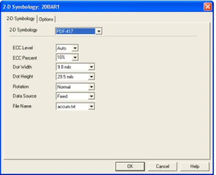
Figure 3-6 2D Symbology Properties Tabs
2 Select the desired 2D bar code type from the 2D Symbol-ogy drop-down list of choices. (Note: Not all bar code
types are available for all printers.)
Note The default values and properties appearing on the 2D
Symbology tab will differ depending on the type of symbology
that you select.
3 On the 2D Symbology tab, set the following bar code
properties as appropriate for this field:
ECC Level/Percent: The Error Correction Control (ECC)
settings determine how resistant the bar code is to destruction, while still maintaining maximum readability. Note that while the higher ECC levels (larger numbers) provide better error correction, they also increase the size of the 2D bar code. The default ECC level setting is Auto. If an Auto ECC level is used then an ECC percent may also be chosen for fine adjustment of the Error Control.
Dot Width/Height: The Dot Width and Height settings
determine the width and height of the 2D bar code (simi-lar to the Bar Width Ratio setting in a linear bar code). The
unit of measurement is mils, where 1mil=1/1000”. Typi-cally, the Dot Width and Height settings are dependent upon the type of printer used and the labeling specifica-tions to be met, if any.
4 Click the Data Source drop-down list and select the
source from which the 2D bar code will get its value. The default data source is Fixed (never changing). See the "Data Sources" chapter for more information.
5 If using a Fixed data source, click the File Name
drop-down list and select the name of the text file that contains the data to be encoded into the bar code. (Note: The text file must reside in the directory specified for text files in the Options > Directories dialog box.)
This file can also be created using Windows Notepad, available from the Tools menu.
6 Click the Options tab to assign a unique Field Name to
this field and if desired, set other optional properties. (Note: Field Names can contain letters and numbers, but no spaces are allowed.)
7 Click OK and then click on the label in the position where
you want to place the 2D bar code.
Adding a Picture 1 Do one of the following:
• On the Draw menu, click Picture.
• Click Add Picture on the Drawtools Bar. The Picture properties tabs appear.
Figure 3-7 Picture Properties Tabs
2 On the Pictures tab, set the following picture properties
as appropriate for this field:
Rotation: Controls the orientation of the picture object.
The options are Normal, Sideways Up, Sideways Down, and Upside Down.
Ratio: Determines if and how the image can be resized.
• Fixed Ratio means both the height and width will
remain proportional as the size changes.
• Stretchable means there is independent control of
the height and the width.
• Non-Resizable means the picture cannot be resized. Preview: Click this box if you want to see a preview of
the selected picture file.
3 Click the Data Source drop-down list and select the
source of the picture object. The default data source is Fixed (never changing). See the "Data Sources" chapter for more information.
4 If using a Fixed data source, click the Pictures drop-down
list and select the name of the picture file (e.g., logo.pcx). (Note: The picture file must reside in the directory speci-fied for picture files in the Options > Directories dialog box.)
5 Click the Options tab to assign a unique Field Name to
this field and if desired, set other optional properties. (Note: Field Names can contain letters and numbers, but no spaces are allowed.)
6 Click OK and then click on the label in the position where
you want to place the picture.
Adding an OLE
Object 1 Do one of the following:
• On the Draw menu, click OLE Object.
• Click Add OLE Object on the Drawtools Bar. The Insert Object dialog box appears.
Figure 3-8 Insert OLE Object
2 Select one of the following options:
• Create New: The Object Type list displays objects
associated with your other installed applications that support Object Linking and Embedding (OLE). Select an object type from the scroll list and click OK. The program associated with the selected object type will open, allowing you to create a new object using that program. (Note: Creating a new object does not create a new file; therefore, these objects are embedded and not linked.)
• Create from File: If the object you want to use on the
label is already saved on your system, use this option to locate it and insert the object as a link. You will be prompted to enter the location and file name, or you can browse to find it.
3 Click OK and then click on the label in the position where
you want to place the object.
Adding a Box 1 Do one of the following:
• On the Draw menu, click Box.
• Click Add Box on the Drawtools Bar. The Box properties appear.
Figure 3-9 Box Properties
2 Specify the thickness and color of the horizontal and
verti-cal sides of the box. If you have a single-color printer, however, the box will print only in that color.
3 Click OK and then click on the label in the position where
you want to place the box (the cursor position will be the upper left corner of the box).
4 The box will appear with a default size. If you want to
change the size of the box, click and drag one of the box's handles until you have reached the desired size.
Adding a Line 1 Do one of the following:
• On the Draw menu, click Line.
• Click Add Line on the Drawtools Bar.
2 Click and drag the cursor (appearing as a crosshair in the
design window) to draw a vertical or horizontal line.
3 To specify the thickness or color of the line, right-click on
Adding a Shape 1 Do one of the following:
• On the Draw menu, click Shape.
• Click Add Shape on the Drawtools Bar.
The Shape properties tabs appear.
Figure 3-10 Shape Properties Tabs
2 On the Shape tab, in the Shape Category drop-down
list, select the category that contains the shape you want. For example, if you are looking for a fire extinguisher icon, select the Fire Safety category. All the available shapes for the selected category appear.
3 Scroll through the displayed shapes and click the shape
you want. The selected shape will appear in the lower por-tion of the dialog box.
Once you have drawn the line on the label, you can click and drag one of the line's handles to change the line's thickness or length.
4 In the Rotation box, select the orientation of the shape.
The options are Normal, Sideways Up, Sideways Down, and Upside Down.
5 In the Ratio box, select one of the following options for
resizing the shape:
• Fixed Ratio means both the height and width will
remain proportional as you change the size. • Stretchable means you have full control over the
height and width of the image.
6 Click the Options tab to assign a unique Field Name to
this field and if desired, set other optional properties. (Note: Field Names can contain letters and numbers, but no spaces are allowed.)
7 Click OK and then click on the label in the position where
you want to place the shape.
Adding TextArt 1 Do one of the following:
• On the Draw menu, click TextArt.
• Click Add TextArt on the Drawtools Bar. The TextArt properties tabs appear.
2 On the Text tab, click the TrueType Fonts drop-down list
and select the font to use for the TextArt object.
3 Set the following TrueType font properties:
Point Size: The size of the font expressed in points. Language: Select from a list of character sets appropriate
for the language you are using.
Style: Select from a list of available styles for the selected
font. For most TrueType fonts, available styles include Nor-mal, Bold, Italic, and Bold & Italic.
4 Click the Data Source drop-down list and select the
source from which the text object will get its value. The default data source is Fixed (never changing). See the "Data Sources" chapter for more information.
5 If adding text with a Fixed data source, in the Text String
box, type the text to be printed on the label.
6 Click the Options tab to assign a unique Field Name to
this field and if desired, set other optional text properties. (Note: Field Names can contain letters and numbers, but no spaces are allowed.)
7 Click the TextArt tab.
If your printer does not support TrueType fonts, they will be processed as graphics. Graphics require more memory, taking longer to print than fonts that are resident on the printer.
Figure 3-12 TextArt Tab
8 Set the following TextArt properties:
Bend text to shape: When this box is checked, the text
will follow the border of the shape selected on the Shape
settings tab.
Alignment: Used to define the horizontal and vertical
alignment characteristics of the TextArt in its allocated space. Available alignment options include Centered (default), Left, Right, and Justified.
Break: Used to define the point where a text break should
occur, when the text has to adapt to the shape. Break options include At any character, At word boundaries, or At carriage return characters.
Char spacing: Used to define the spacing between
char-acters. Spacing options include Normal (default), Dense, Loose, and Custom. You can select the Custom option to define custom character spacing based on a scale of 20 to 200 (with the default setting of 100 being standard spac-ing).
Rotated characters: Used to rotate individual TextArt
9 If you want to apply color to the TextArt object text, click
the Text Color tab to access the color settings for the Fill, Outline, and Shadow colors.
10 If you would like a shape to appear in the background of
the TextArt object, click the Shape settings tab and select the desired shape. Shape options include Ellipse, Line, Polygon, Polyline, Rectangle, and Round rectangle.
11 If desired, use the settings on the Shape settings tab to
specify background and border settings.
12 Click OK and then click on the label in the position where
you want to place the TextArt object.
Adding a
RichTextField 1 Do one of the following:
• On the Draw menu, click RichTextField.
• Click Add RichTextField on the Drawtools Bar. The RichTextField properties tabs appear.
2 On the RichTextField tab, click the Data Source
drop-down list and select the source from which the RichText-Field object will get its value. The default data source is Fixed (never changing). See the "Data Sources" chapter for more information.
3 If adding text with a Fixed data source, click the Edit Text
button to create the text using the RichTextField Input dialog box.
Figure 3-14 RichTextField Input Dialog Box
Use the text style and formatting options on the top tool-bar to create the RichTextField text, and then click OK to return to the RichTextField tab.
4 Click the Options tab to assign a unique Field Name to
this field. (Note: Field Names can contain letters and numbers, but no spaces are allowed.)
5 If you would like a shape to appear in the background of
the RichTextField object, click the Shape settings tab and select the desired shape. Shape options include Ellipse, Line, Polygon, Polyline, Rectangle, and Round rectangle.
6 If desired, use the settings on the Shape settings tab to
specify background and border settings.
7 Click OK and then click on the label in the position where
Working with Placed Objects
Moving an Object
on the Label 1 Place the mouse pointer over the selected object. 2 Click the left mouse button and drag to move the object to
the desired location.
Sizing an Object on
the Label 1 To size the object while keeping the aspect ratio of the height and width the same, click on one of the four
cor-ners of the object handles (so the cursor is at a diagonal).
2 Drag to the desired size.
For More Information on Designing Labels
For detailed information on all label design functions available in this label design software, use the program’s online Help. Help is available by selecting Help Topics from the Help menu or by pressing F1.
I
Numerics
2D bar codes 3-10 adding 3-10 properties 3-11
A
accumulator files 2-3 adding
2D bar codes 3-10 bar codes 3-8 boxes 3-15 lines 3-15 OLE objects 3-14 paragraphs 3-6 pictures 3-12 RichTextField 3-20 shapes 3-16 text 3-3 TextArt 3-17 aligning objects 1-7
B
bar codes 3-8 adding 3-8 properties 3-9 boxes 3-15
adding 3-15 properties 3-15
C
command files 1-6
CommWatch 2-3 Configuration 1-5 coordinates 1-8 create new label 3-1 cursor position 1-8
D
data dictionary 2-3 data source
definition 2-1 types 2-2 DataWatch Server 1-6 date 2-3
dBase 2-2 DDE Server 1-6 Directories 1-5 display modes 1-3 display settings 1-8 Drawtools Bar 1-4
F
fixed data source 2-2 Float Bar 1-7
G
graphics 3-12 grid 1-2 grid display 1-8
I
inches 1-8
installing a printer 1-9 interface 1-1
L
Label Select 1-6 label setup 3-1 language selection 1-8 lines 3-15
linked data source 2-2
M
Menu Bar 1-1 menus 1-1 millimeters 1-8 moving objects 3-22
N
Name mode 1-3 new label 3-1
O
objects adding 3-3 aligning 1-7 moving 3-22 sizing 3-22 ODBC 2-3 OLE DB 2-3 OLE objects 3-14 opening a label 3-2 Options Bar 1-5
P
paragraphs 3-6 adding 3-6 properties 3-6 pick list 2-3 pictures 3-12
adding 3-12 properties 3-13 preview label 3-3 printer
setup 1-9 PrintPad 1-5
R
RichTextField 3-20 adding 3-20 Rotation button 1-8 ruler colors 1-8 rulers 1-8
S
serial file 2-3
Server Bar 1-4, 1-5, 1-6 setup 3-1
shapes 3-16 adding 3-16 properties 3-16 shift code 2-3 sizing objects 3-22 snap to grid 1-2 starting the program 1-1 Status Bar 1-8
Style Bar 1-2
T
text 3-3 adding 3-3 properties 3-4 TextArt 3-17
adding 3-17 properties 3-19 time 2-3
toolbars 1-2, 1-4, 1-5, 1-6, 1-7, 1-8
TrueType font 3-5, 3-18 two-dimensional bar codes 3-10
U
Undo 1-3
units of measure 1-8
V
Value mode 1-3 view modes 1-3
W
when printed data source 2-2
X
Copyright 2012 Teklynx Newco SAS. All rights reserved. Printed in the USA 06/12. TEKLYNX and LABELVIEW are trademarks of Teklynx Newco SAS. All other brands and product names are trademarks of their respective owners.