REFERENCE ARCHITECTURE FOR 500-SEAT AND
1000-SEAT VIRTUAL
DESKTOP
INFRASTRUCTURE
C
ITRIX
X
EN
D
ESKTOP
7
B
UILT ON
C
ISCO
UCS
B200-M3
B
LADE
S
ERVERS
WITH
EMC
VNX
E AND
M
ICROSOFT
H
YPER
-V
2012
2
Table of Contents
1. Overview ... 9
1.1. About this Document... 9
2. Solution Component Benefits ... 9
2.1. Benefits of Cisco Unified Computing System ... 9
2.1.1. Benefits of Cisco Nexus 5548UP ...10
2.2. Benefits of EMC VNX Family of Storage Controllers ...11
2.2.1. The EMC VNX Family ...11
2.2.2. VNXe Series – Simple, Efficient, Affordable ...11
2.2.3. VNX Series - Simple, Efficient, Powerful ...12
2.3. Benefits of Microsoft Windows Server 2012 with Hyper-V ...12
2.4. Benefits of Citrix XenDesktop 7 ...13
2.5. Audience ...13
3. Summary of Main Findings ...14
4. Architecture...15 4.1. Hardware Deployed ...15 4.2. Logical Architecture...16 4.3. Software Revisions ...17 4.4. Configuration Guidelines ...18 4.4.1. VLAN ...18 4.4.2. Hyper-V Clustering ...19 5. Infrastructure Components ...20
5.1. Cisco Unified Computer System (UCS) ...20
5.1.1. Cisco Unified Computing Components ...20
5.1.2. Cisco Fabric Interconnects ...22
5.1.3. Cisco IO Modules (Fabric Extenders) ...22
5.1.4. Cisco UCS Chassis ...23
5.1.5. Cisco UCS Manager ...23
5.1.6. Cisco UCS B200 M3Blade Servers...23
5.1.7. Cisco Virtual Interface Card (VIC) Converged Network Adapter ...24
5.2. EMC VNXe3300...25
3
5.2.2. Software suites available...26
5.2.3. Software packs available ...26
5.3. Microsoft Technologies...26
5.3.1. Windows Server 2012 ...26
5.3.2. Failover Clustering ...27
5.3.3. Clustered Shared Volumes...27
5.3.4. Networking Support ...27
5.3.5. Hyper-V ...28
5.3.6. Hyper-V Server 2012 ...28
5.3.7. SQL Server 2012...28
5.3.8. System Center Virtual Machine Manager 2012 SP1 ...29
5.4. Citrix XenDesktop 7 ...29
5.4.1. Enhancements in This Release ...29
5.4.2. FlexCast Technology ...30
5.4.3. High-Definition User Experience (HDX) Technology ...32
5.4.4. Citrix XenDesktop 7 Desktop and Application Services ...32
5.4.5. Provisioning Services 7...33
6. Solution Architecture ...34
6.1. Citrix Design Fundamentals ...36
6.1.1. Citrix Hosted Shared Desktop Design Fundamentals ...37
6.2. EMC Storage Architecture Design ...42
6.2.1. High Availability ...42
6.2.2. Data Protection ...43
6.3. Solution Validation ...43
6.3.1. Configuration Topology for Scalable Citrix XenDesktop 7 Hybrid Virtual Desktop Infrastructure on Cisco Unified Computing System and EMC Storage...43
6.4. Configuration Topology for Citrix XenDesktop 7on Cisco Unified Computing System with VNXe Storage ...45
6.5. Cisco UCS Configuration ...46
6.6. Base Cisco UCS Configuration...47
6.6.1. Firmware Update ...47
6.6.2. Acknowledge the Chassis ...48
6.6.3. Server Port Configuration ...49
4
6.6.5. VNXe Appliance Port Configuration...53
6.6.6. KVM IP Address Pool ...54
6.6.7. MAC Address Pool...56
6.6.8. UUID Suffix Pool ...56
6.6.9. IQN Pool ...57
6.6.10. Server Pool and Related Policies (Optional) ...57
6.6.11. Local Disk Configuration...59
6.6.12. BIOS Policy ...60
6.6.13. Power Control Policy ...61
6.6.14. Scrub Policy...62
6.6.15. Host Firmware Package...63
6.6.16. QOS Policies ...64
6.6.17. Steps to Enable QOS on the Cisco Unified Computing System ...66
6.6.18. iSCSI Adapter Policy...68
6.6.19. VLANs and vNIC Templates ...69
6.6.20. iSCSI Boot Policy ...73
6.6.21. Service Profile Template ...74
6.6.22. Create Service Profiles ...80
6.6.23. Configure iSCSI Boot LUNS for Each Service Profile ...81
6.7. LAN Configuration ...84
6.8. SAN Configuration...84
6.8.1. Boot from SAN benefits ...84
6.9. EMC VNXe Storage Configuration ...85
6.9.1. iSCSI Host Configuration...86
6.9.2. iSCSI Server Configuration ...89
6.9.3. iSCSI Storage Creation...92
6.9.4. CIFS Server Creation ...96
6.9.5. CIFS Share Storage Creation – Profile Share ...98
6.9.6. CIFS Share Storage Creation – vDisk Share ... 103
6.10. Installing and Configuring Microsoft Server 2012... 106
6.10.1. Infrastructure Servers ... 106
6.10.2. VDI Hosts ... 120
5
6.11. Installing and Configuring SQL Server 2012 SP1 ... 123
6.11.1. Pass-Through Storage Configuration ... 124
6.11.2. SQL Server 2012 – Installation Pre-requisites... 129
6.11.3. SQL Server 2012 Installation ... 129
6.11.4. AlwaysOn Application Group ... 139
6.11.5. Log File Management ... 147
6.12. Installing and Configuring System Center 2012 Virtual Machine Manager ... 148
6.13. Installing and Configuring Cisco Nexus 1000V Virtual Switch Manager and Virtual Ethernet Modules 154 6.13.1. Installing Cisco Nexus 1000V Virtual Switch... 155
6.13.2. Installing and Configuring the Virtual Supervisor Modules (VSM) ... 159
6.13.3. Cisco Nexus 1000V for Hyper-V Configuration ... 173
6.14. Installing and Configuring Citrix XenDesktop... 187
6.14.1. Installing Provisioning Services ... 191
6.14.2. Installation of the Second PVS Server ... 212
6.14.3. Installing the Delivery Controller ... 219
6.14.4. XenDesktop Controller Configuration ... 228
6.14.5. Additional XenDesktop Controller Configuration... 233
6.14.6. Configure VM Hosting, Connections, and Resources ... 235
6.14.7. Installing and Configuring StoreFront ... 239
7. Desktop Delivery Infrastructure - Citrix ... 245
7.1. Overview of desktop delivery... 245
7.1.1. PVS vDisk Image Management ... 246
7.1.2. Overview – Golden Image Creation... 246
7.2. Installing the XenDesktop 7 Virtual Desktop Agent ... 247
7.3. Citrix User Profile Management Servers – CITRIX ... 251
7.3.1. Install and Configuration of User Profile Manager ... 251
7.4. Microsoft Windows 7 and Windows Server 2012 Golden Image Creation ... 254
7.4.1. Microsoft Windows 7 and Windows Server 2012 OS Configurations ... 254
7.4.2. Installing the PVS Target Device Software ... 255
7.4.3. Running the PVS Imaging Wizard ... 257
7.4.4. Installation of Login VSI Software ... 261
6
7.4.6. Conversion to PVS vDisk... 263
7.4.7. Write-Cache Drive Sizing and Placement... 263
7.5. Citrix Provisioning Services ... 264
7.5.1. Creating the Virtual Machine Manager Templates ... 264
7.5.2. Process to Create Virtual Desktops using PVS Wizard ... 271
8. Test Setup and Configurations ... 281
8.1. Cisco UCS Test Configuration for Single Blade Scalability of Hosted Shared Desktops ... 282
8.2. Cisco UCS Test Configuration for Single Blade Scalability of Hosted Virtual Machines ... 283
8.3. Cisco UCS Test Configuration for Single Blade Scalability for a Mixed Hosted Shared and Hosted Virtual Workload ... 285
8.4. Cisco UCS Test Configuration for a Single-Chassis 500-User Configuration ... 286
8.5. Cisco UCS Test Configuration for a Two-Chasses 1000-User Configuration ... 288
8.6. Test Methodology and Success Criteria ... 289
8.6.1. Load Generation ... 289
8.6.2. User Workload Simulation – Login VSI ... 289
8.6.3. Testing Procedure ... 291
8.6.4. Success Criteria... 293
9. Login VSI Test Result ... 296
9.1. Cisco UCS B200-M3 Single-Server Scalability Results for Hosted Shared Desktops ... 296
9.2. Cisco UCS B200-M3 Single-Server Scalability Results for Hosted Virtual Desktops ... 300
9.3. Cisco UCS B200-M3 Recommended Single-Server Mixed Desktop Workload ... 303
9.4. Cisco UCS 500-User Scalability Results... 305
9.4.1. EMC VNXe Performance... 306
9.4.2. VDI Host ... 307
9.4.3. XenDesktop Controllers ... 311
9.4.4. Provisioning Services ... 312
9.4.5. SQL Servers ... 313
9.4.6. System Center Virtual Machine Manager and StoreFront ... 314
9.4.1. Active Directory ... 315
9.5. Cisco UCS 1000-User Scalability Results ... 317
9.5.1. EMC VNXe Performance... 317
9.5.2. VDI Host ... 319
7
9.5.4. Provisioning Services ... 324
9.5.5. SQL Servers ... 325
9.5.6. System Center Virtual Machine Manager and StoreFront ... 326
9.5.7. Active Directory ... 327
10. Scalability Considerations and Guidelines... 329
10.1. Cisco UCS Configuration ... 329
10.2. EMC VNXe Storage Configuration... 329
10.2.1. Capacity planning... 329
10.2.2. Performance Planning ... 330
10.2.3. Scalability Planning... 330
10.3. Microsoft Windows Server 2012 with Hyper-V 2012 Configuration ... 330
10.3.1. Virtual Machines ... 330
10.3.2. Server Running Hyper-V ... 331
10.3.4. Failover Clusters and Hyper-V ... 332
10.4. Citrix XenDesktop 7 Configuration – Citrix ... 333
11. Other Considerations ... 333
11.1. Power Outages and Boot Sequence ... 333
11.1.1. Recommended Boot Sequence ... 334
11.2. Microsoft Cluster Maintenance ... 334
11.3. SQL Server AlwaysOn Groups ... 334
12. References ... 335
12.1. Cisco Reference Documents – Cisco ... 335
12.2. EMC Reference Documents – EMC ... 335
12.3. Microsoft Reference Documents... 336
12.4. Citrix Reference Documents ... 337
13. Appendix... 338
13.1. Performance Charts for Scalability Tests ... 338
13.2. Sample Cisco Nexus 6248-UP Configurations ... 352
13.2.1. 6248UP – A ... 377
13.3. Sample Cisco Nexus 1000V Configuration... 401
13.3.1. N1000V-1 ... 406
13.4. Sample PowerShell Scripts ... 411
8
13.4.2. Enable Dynamic Memory ... 413
13.4.3. Disable Dynamic Memory... 414
13.4.4. Query the XenDesktop Database Connection Strings ... 415
13.4.5. Test the XenDesktop Database Connection String ... 416
13.4.6. Change the XenDesktop Database Connection String ... 416
9
1.
Overview
1.1.
About this Document
This document describes the reference architecture for a 500-seat and 1000-seat virtual desktop infrastructure using Citrix XenDesktop 7 built on Cisco UCS B200-M3 Blade Servers with EMC VNXe3300 and Microsoft Hyper-V 2012.
Industry trends indicate a vast data center transformation toward shared infrastructures. Enterprise customers are moving away from silos of information and toward shared infrastructures, to virtualized environments, and eventually to the cloud to increase agility and reduce costs.
This document provides the architecture and design of a virtual desktop infrastructure that can grow from 500 users to 1000 users. The infrastructure is 100% virtualized on Microsoft Hyper-V Server 2012 with third-generation Cisco UCS B-Series B200 M3 Blade Servers iSCSI booting from an EMC VNXe3300 storage array.
The virtual desktops are powered using Citrix Provisioning Server 7 and Citrix XenDesktop 7, with a mix of hosted shared desktops (70%) and pooled desktops (30%) to support the user population. Where applicable, the document provides best practice recommendations and sizing guidelines for customer deployments of XenDesktop 7 on the Cisco Unified Computing System.
2.
Solution Component Benefits
Each of the components of the overall solution materially contributes to the value of functional design contained in this document.
2.1.
Benefits of Cisco Unified Computing System
Cisco Unified Computing System™ is the first converged data center platform that combines industry-standard, x86-architecture servers with networking and storage access into a single converged system. The system is entirely programmable using unified, model-based management to simplify and speed deployment of enterprise-class applications and services running in bare-metal, virtualized, and cloud computing environments.
Benefits of the Unified Computing System include: Architectural flexibility
Cisco UCS B-Series blade servers for infrastructure and virtual workload hosting Cisco UCS C-Series rack-mount servers for infrastructure and virtual workload Hosting Cisco UCS 6200 Series second generation fabric interconnects provide unified blade, network
and storage connectivity
Cisco UCS 5108 Blade Chassis provide the perfect environment for server type, multi-purpose workloads in a single containment
10
Infrastructure Simplicity
Converged, simplified architecture drives increased IT productivity
Cisco UCS management results in flexible, agile, high performance, self-integrating information technology with faster ROI
Fabric Extender technology reduces the number of system components to purchase, configure and maintain
Standards-based, high bandwidth, low latency virtualization-aware unified fabric delivers high density, excellent virtual desktop user-experience
Business Agility
Model-based management means faster deployment of new capacity for rapid and accurate scalability
Scale up to 16 chassis and up to 128 blades in a single Cisco UCS management domain Leverage Cisco UCS Management Packs for System Center 2012 for integrated management
2.1.1.
Benefits of Cisco Nexus 5548UP
The Cisco Nexus 5548UP Switch delivers innovative architectural flexibility, infrastructure simplicity, and business agility, with support for networking standards. For traditional, virtualized, unified, and high-performance computing (HPC) environments, it offers a long list of IT and business advantages, including:
Architectural Flexibility
Unified ports that support traditional Ethernet, Fiber Channel (FC), and Fiber Channel over Ethernet (FCoE)
Synchronizes system clocks with accuracy of less than one microsecond, based on IEEE 1588 Offers converged Fabric extensibility, based on emerging standard IEEE 802.1BR, with Fabric
Extender (FEX) Technology portfolio, including the Nexus 1000V Virtual Distributed Switch
Infrastructure Simplicity
Common high-density, high-performance, data-center-class, fixed-form-factor platform Consolidates LAN and storage
Supports any transport over an Ethernet-based fabric, including Layer 2 and Layer 3 traffic Supports storage traffic, including iSCSI, NAS, FC, RoE, and IBoE
Reduces management points with FEX Technology Business Agility
Meets diverse data center deployments on one platform
Provides rapid migration and transition for traditional and evolving technologies Offers performance and scalability to meet growing business needs
11
Specifications At-a-Glance
A 1 -rack-unit, 1/10 Gigabit Ethernet switch
32 fixed Unified Ports on base chassis and one expansion slot totaling 48 ports
The slot can support any of the three modules: Unified Ports, 1/2/4/8 native Fiber Channel, and Ethernet or FCoE
Throughput of up to 960 Gbps
2.2.
Benefits of EMC VNX Family of Storage Controllers
2.2.1.
The EMC VNX Family
The EMC VNX Family delivers industry leading innovation and enterprise capabilities for file, block, and object storage in a scalable, easy-to-use solution. This next-generation storage platform combines powerful and flexible hardware with advanced efficiency, management, and protection software to meet the demanding needs of today’s enterprises.
All of this is available in a choice of systems ranging from affordable entry-level solutions to high
performance, petabyte-capacity configurations servicing the most demanding application requirements. The VNX family includes the VNXe Series, purpose-built for the IT generalist in smaller environments , and the VNX Series , designed to meet the high-performance, high scalability, requirements of midsize and large enterprises.
Figure 1 VNX Family
2.2.2.
VNXe Series – Simple, Efficient, Affordable
The VNXe Series was designed with the IT generalist in mind and provides an affordable, integrated storage system for small-to-medium businesses as well as remote offices, and departments in larger enterprise businesses. The VNXe series provides true storage consolidation with a unique application– driven approach that eliminates the boundaries between applications and their storage.
This simple application-driven approach to managing shared storage makes the VNXe series ideal for IT generalists/managers and application administrators who may have limited storage expertise. EMC
12
Unisphere for the VNXe series enables easy, wizard-based provisioning of storage for Microsoft, Exchange, file shares, iSCSI volumes, VMware, and Hyper-V. VNXe supports tight integration with VMware to further facilitate efficient management of virtualized environments. Complemented by Unisphere Remote, the VNXe is also ideal for remote office-branch office (ROBO) deployments. Built-in efficiency capabilities, such as file de-duplication with compression and thin provisioning result in streamlined operations and can save up to 50 percent in upfront storage costs. Software packs aimed at facilitating backup, remote data protection, and disaster recovery include features such as easy-to-configure application snapshots.
The VNXe series supports high availability by using redundant components – power supplies, fans, and storage processors – as well as dynamic failover and failback. Additionally, the VNXe series supports the ability to upgrade system software or hardware while the VNXe system is running. It also delivers single click access to a world of resources such as comprehensive online documentation, training, and how-to-videos to expand your knowledge and answer questions.
2.2.3.
VNX Series - Simple, Efficient, Powerful
The EMC VNX flash-optimized unified storage platform delivers innovation and enterprise capabilities for file, block, and object storage in a single, scalable, and easy-to-use solution. Ideal for mixed workloads in physical or virtual environments, VNX combines powerful and flexible hardware with advanced efficiency, management, and protection software to meet the demanding needs of today’s virtualized application environments.
VNX includes many features and enhancements designed and built upon the first generation’s success. These features and enhancements include:
More capacity with multicore optimization with Multicore Cache, Multicore RAID, and Multicore FAST Cache (MCx™)
Greater efficiency with a flash-optimized hybrid array
Better protection by increasing application availability with active/active
Easier administration and deployment by increasing productivity with new Unisphere® Management Suite
Next-Generation VNX is built to deliver even greater efficiency, performance, and scale than ever before.
2.3.
Benefits of Microsoft Windows Server 2012 with Hyper-V
Microsoft Windows Server 2012 with Hyper-V builds on the architecture and functionality of Microsoft Hyper-V 2008 R2 allowing you to run the largest workloads in your virtualized environment. Windows Server 2012 with Hyper-V offers support for up to 64 virtual processors, 1 terabyte of memory per guest VM, and 4,000 virtual machines on a 64-node cluster. With Hyper-V, you can support Offloaded Data Transfer and improved Quality of Service to enforce minimum bandwidth requirements (even for network storage). High-availability options include incremental backup support, enhancements in clustered environments to support virtual Fiber Channel adapters within the virtual machine, and inbox
13
NIC Teaming. Windows Server 2012 Hyper-V can also use server message block file shares for virtual storage. This new option is simple to provision and offers performance capabilities and features that rival those available with Fiber Channel storage area networks. The Hyper-V Extensible Switch within Windows Server 2012 with Hyper-V gives you an open, extensible switch to help support security and management needs. You can build your own extensions, or use partner extensions to support these needs. Hyper-V works with Microsoft System Center 2012 SP1 management tools to handle your multi-server virtualization environment. With new management support for Hyper-V, you can fully automate management tasks and help reduce the administrative overhead costs of your environment.
Hyper-V provides a dynamic, reliable, and scalable virtualization platform combined with a single set of integrated management tools to manage both physical and virtual resources, enabling creation of an agile and dynamic data center.
2.4.
Benefits of Citrix XenDesktop 7
There are many reasons to consider a virtual desktop solution. An ever growing and diverse base of users, an expanding number of traditional desktops, an increase in security mandates and government regulations, and the introduction of Bring Your Own Device (BYOD) initiatives are factors that add to the cost and complexity of delivering and managing desktop and application services.
Citrix XenDesktop™ 7 transforms the delivery of Microsoft Windows apps and desktops into a secure, centrally managed service that users can access on any device, anywhere. The release focuses on delivering these benefits:
Mobilizing Microsoft Windows application delivery, bringing thousands of corporate applications to mobile devices with a native-touch experience and high performance Reducing costs with simplified and centralized management and automated operations Securing data by centralizing information and effectively controlling access
Citrix XenDesktop 7 promotes mobility, allowing users to search for and subscribe to published resources, enabling a service delivery model that is cloud-ready.
The release follows a new unified FlexCast 2.0 architecture for provisioning all Windows apps and desktops either on hosted-shared RDS servers or VDI-based virtual machines. The new architecture combines simplified and integrated provisioning with personalization tools. Whether a customer is creating a system to deliver just apps or complete desktops, Citrix XenDesktop 7 leverages common policies and cohesive tools to govern infrastructure resources and access.
2.5.
Audience
This document describes the architecture and deployment procedures of an infrastructure comprised of Cisco, EMC, Microsoft and Citrix virtualization. The intended audience of this document includes, but is not limited to, sales engineers, field consultants, professional services, IT managers, partner
14
3.
Summary of Main Findings
The combination of technologies from Cisco Systems, Inc, Citrix Systems, Inc., Microsoft and EMC produced a highly efficient, robust and affordable Virtual Desktop Infrastructure (VDI) for a hosted virtual desktop deployment. Key components of the solution included:
This design is Cisco’s Desktop Virtualization Simplified Design, with compute and storage converged at the Cisco UCS Fabric Interconnect. In this design, the Cisco UCS Fabric
Interconnects are uplinked directly to the Layer 3 network, reducing the solution footprint and cost. This design is well suited for smaller deployments of virtual desktop infrastructure.
Local storage in the form of two 400 GB Enterprise SSD’s provides fast local storage for the Citrix Provisioning Services write-cache drives and significantly reduces the impact on the primary EMC VNXe3300 storage array.
Cisco UCS B200 M3 half-width blade with dual 12-core 2.7 GHz Intel Ivy Bridge (E5-2697v2) processors and 384GB of memory supports 25% more virtual desktop workloads than the previously released Sandy Bridge processors on the same hardware.
The 500-user design is based on using one Unified Computing System chassis with three Cisco UCS B200 M3 blades for virtualized desktop workloads and oneCisco UCS B200 M3 blade for virtualized infrastructure workloads.
The 1000-user design is based on using two Cisco Unified Computing System chassis with five Cisco UCS B200 M3 blades for virtualized desktop workloads and one Cisco UCS B200 M3 blade for virtualized infrastructure workloads.
All log in and start workloads up to steady state were completed in 30-minutes without pegging the processor, exhausting memory or storage subsystems.
The rack space required to support the 500 users was a single rack of approximately 22 rack units. The space required to support 1000 users in a fully redundant configuration was only 28 RUs, which translates to an additional Cisco UCS 5108 chassis.
Pure Virtualization: This Cisco Validated Design presents a validated design that is 100%
virtualized on Microsoft Hyper-V 2012. All of the Windows 7 SP1 virtual desktops and supporting infrastructure components, including Active Directory, Provisioning Servers, SQL Servers, and XenDesktop delivery controllers, were hosted as virtual servers.
Cisco maintains our industry leadership with our new Cisco UCS Manager 2.1.3(a) software that simplifies scaling, guarantees consistency, and eases maintenance.
Our 10G unified fabric story gets additional validation on second generation Cisco UCS 6200 Series Fabric Interconnects as Cisco runs more challenging workload testing, while maintaining unsurpassed user response times.
EMC’s VNXe3300 system provides storage consolidation and outstanding efficiency for up to 1000 users.
Citrix XenDesktop™ 7 follows a new unified product architecture that supports both hosted-shared desktops and applications (RDS) and complete virtual desktops (VDI). This new
XenDesktop release simplifies tasks associated with large-scale VDI management. This modular solution supports seamless delivery of Windows apps and desktops as the number of users increase. In addition, HDX enhancements help to optimize performance and improve the user
15
experience across a variety of endpoint device types, from workstations to mobile devices including laptops, tablets, and smartphones.
For hosted shared desktop sessions, the best performance was achieved when the number of vCPUs assigned to the XenDesktop 7 RDS virtual machines did not exceed the number of hyper-threaded cores available on the server. In other words, maximum performance is obtained when not overcommitting the CPU resources for hosted shared desktops.
4.
Architecture
4.1.
Hardware Deployed
The architecture deployed is highly modular. While each customer’s environment might vary in its exact configuration, when the reference architecture contained in this document is built, it can easily be scaled as requirements and demands change. This includes scaling both up (adding additional resources within a Cisco UCS Domain) and out (adding additional Cisco UCS Domains and VNX Storage arrays). The 500- and 1000-user XenDesktop 7 solution includes Cisco networking, Cisco Unified Computing System, and EMC VNXe storage, which fits into a single data center rack, including the access layer network switches.
This Cisco Validated Design document details the deployment of the 500- and 1000-user configurations for a mixed XenDesktop workload featuring the following software:
Citrix XenDesktop 7 Pooled Hosted Virtual Desktops with PVS write cache on Tier0 storage Citrix XenDesktop 7 Shared Hosted Virtual Desktops with PVS write cache on Tier0 storage Citrix Provisioning Server 7
Citrix User Profile Manager Citrix StoreFront 2.0
Cisco Nexus 1000V Distributed Virtual Switch Microsoft Windows Hyper-V 2012 Hypervisor
Microsoft System Center 2012 Virtual Machine Manager SP1 Microsoft SQL Server 2012 SP1
16
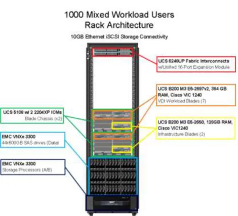
Figure 2: Workload Architecture
The workload contains the following hardware as shown in Figure 2: Workload Architecture: Two Cisco UCS 6248UP Series Fabric Interconnects
Two Cisco UCS 5108 Blade Server Chassis (1 for each 500-users of capacity) with two 2204XP IO Modules per chassis
Five Cisco UCS B200 M3 Blade Servers with Intel E5-2697v2 processors, 384GB RAM, and VIC1240 mezzanine cards for the mixed desktop virtualization workloads.
Two Cisco UCS B200 M3 Blade Servers with Intel E5-2650 processors, 128 GB RAM, and VIC1240 mezzanine cards for the infrastructure virtualization workloads
One EMC VNXe3300 dual controller storage system for HA, 44 SAS disks across 3 shelves, 10GE ports for network connectivity.
The EMC VNXe3300 disk shelf configurations are detailed in Section 5.4 Storage Architecture Design later in this document.
4.2.
Logical Architecture
The logical architecture of the validated design is very similar between the 500-user and 1000-user configuration. The design was architected to support 500 users within a single chassis and four blades. The 1000-users configuration would require seven blades across two chassis, which would also add physical redundancy for the chassis. If full redundancy is required within the 500-user configuration, a second infrastructure host (INFRA-2) can be added or the virtual machines hosted on INFRA-2 could be placed on VDI 1-4. The table below outlines all the servers in the two configurations.
17
Table 1: Infrastructure Architecture
Server Name Location Purpose
INFRA-1 Physical – Chassis 1 Clustered Windows 2012 Datacenter server for infrastructure guests
VDI1-2 Physical – Chassis 1 Mixed workload Hyper-V 2012 server VDI1-3 Physical – Chassis 1 Mixed workload Hyper-V 2012 server
VDI1-4 Physical – Chassis 1 Mixed workload Hyper-V 2012 server – (N+1) spare capacity
INFRA-2 Physical – Chassis 2 Clustered Windows 2012 Datacenter server for infrastructure guests (1000-user
configuration)
VDI2-1 Physical – Chassis 2 Mixed workload Hyper-V 2012 server (1000 – user configuration)
VDI2-2 Physical – Chassis 2 Mixed workload Hyper-V 2012 server (1000-user configuration)
AD-DC1 Virtual – INFRA-1 Active Directory Domain Controller
EXC1 Virtual – INFRA-1 XenDesktop 7 controller
PVS1 Virtual – INFRA-1 Provisioning Services streaming server SCVMM1/
SCVMM2
Virtual – INFRA-1 System Center 2012 Virtual Machine Manager Server
SFS1 Virtual – INFRA-1 StoreFront Services server
SQL1 Virtual – INFRA-1 SQL Server (primary) for AlwaysOn groups Nexus1000V 1 Virtual – INFRA-1 Nexus 1000-V VSM HA node
Nexus1000V 3 Virtual – INFRA-1 Nexus 1000-V VSM HA node
HSDGold Virtual – INFRA-1 Used to manage the PVS golden image for the Hosted Shared Desktop server image XDGold Virtual – INFRA-1 Used to managed the PVS golden image for
the Windows 7 XenDesktop VDI image AD-DC2 Virtual – INFRA-2 Active Directory Domain Controller
EXC2 Virtual – INFRA-2 XenDesktop 7 controller
PVS2 Virtual – INFRA-2 Provisioning Services streaming server SQL2 Virtual – INFRA-2 SQL Server (secondary) for AlwaysOn groups Nexus1000V 2 Virtual – INFRA-2 Nexus 1000-V VSM HA node
Nexus1000V 4 Virtual – INFRA-2 Nexus 1000-V VSM HA node
4.3.
Software Revisions
This section includes the software versions of the primary products installed in the environment. Table 2: Software Revisions
Vendor Product Version
Cisco UCS Firmware 2.1(3a)
Cisco UCS Manager 2.1(3a)
Cisco Nexus 1000V for Hyper-V 5.2(1) SM1 (5.1)
Citrix XenDesktop 7.0.0.3018
18
Citrix StoreFront Services 2.0.0.90
Microsoft System Center 2012 Virtual Machine Manager SP1
3.1.6027.0
Microsoft Windows Server 2012 DataCenter 6.2.9200 Build 9200
Microsoft Hyper-V Server 2012 6.2.9200 Build 9200
Microsoft SQL Server 2012 SP1 11.0.30000.0 (x64)
4.4.
Configuration Guidelines
This section provides guidelines for situations where additional guidance may be necessary.
4.4.1.
VLAN
The VLAN configuration recommended for the environment includes a total of eight VLANs as outlined in the table below.
Table 3: VLAN Configuration
VLAN Name VLAN ID Use
MGMT 60 Management. Used for the Hyper-V hosts and physical
hardware. Should always be assigned to the first vNIC on any host and never connected to a Hyper-V virtual switch.
INFRA 61 Infrastructure. Used for all the virtualized infrastructure hosts, such as the XenDesktop Controllers, Provisioning Servers, SQL Servers, etc.
PVS-VDI 62 Provisioning Services and VDI. Used as the only network available for the provisioned hosted shared and virtual desktops.
CSV 63 Clustered Shared Volumes and Cluster heartbeat. Used only on the infrastructure cluster hosts for cluster communication and data volume traffic.
LMIGR 64 LiveMigration for Infrastructure Cluster. Used only on the infrastructure cluster hosts for live migration of guests between the two hosts.
STORAGE-A 65 iSCSI traffic on Fabric A. Used only for iSCSI traffic on channel A.
STORAGE-B 66 iSCSI traffic on Fabric B. Used only for iSCSI traffic on channel B.
STORAGE-NULL
99 Null Storage VLAN. Used temporarily during the Windows 2012 install to prevent the install from detecting multiple storage paths to the iSCSI volume.
As described in section 4.2 Logical Architecture section, the only clustering in the design is between INFRA-1 and INFRA-2 when 1000-users are involved or full redundancy is required for the infrastructure hosts. If INFRA-2 is not included in the design, then the clustering VLANs 63 and 64 can be omitted.
19
4.4.2.
Hyper-V Clustering
This section describes the quidelines about configuring Microsoft Hyper-V Clustering.
4.4.2.1.
Network Configuration Guidelines
Microsoft recommends having a minimum of two networks for your failover cluster: a public network that allows clients to connect to the cluster and a separate network that is used only for communication between the clustered servers. You can configure additional networks for specific storage options or for redundancy as needed.
When you use identical network adapters for a network, also use identical communication settings on those adapters (for example, Speed, Duplex Mode, Flow Control, and Media Type). Also, compare the settings between the network adapter and the switch it connects to and make sure that no settings are in conflict.
If you have private networks that are not routed to the rest of your network infrastructure, make sure that each of these private networks uses a unique subnet. This is necessary even if you give each network adapter a unique IP address. For example, if you have a cluster node in a central office that uses one physical network, and another node in a branch office that uses a separate physical network, do not specify 10.0.0.0/24 for both networks, even if you give each adapter a unique IP address.
4.4.2.2.
Prestage Cluster Computer Objects in Active Directory
When you create a failover cluster by using the Create Cluster Wizard or by using Windows PowerShell, you must specify a name for the cluster. If you have sufficient permissions when you create the cluster, the cluster creation process automatically creates a computer object in AD DS that matches the cluster name. This object is called the cluster name object or CNO. Through the CNO, virtual computer objects (VCOs) are automatically created when you configure clustered roles that use client access points. For example, if you create a highly available file server with a client access point that is named FileServer1, the CNO will create a corresponding VCO in AD DS.
To create the CNO automatically, the user who creates the failover cluster must have the Create
Computer objects permission to the organizational unit (OU) or the container where the servers that will form the cluster reside. To enable a user or group to create a cluster without having this permission, a user with appropriate permissions in AD DS (typically a domain administrator) can prestage the CNO in AD DS. This also provides the domain administrator more control over the naming convention that is used for the cluster, and control over which OU the cluster objects are created in.
Instructions about how to pre-stage the Cluster Name Object can be found here: http://technet.microsoft.com/en-us/library/dn466519.aspx
4.4.2.3.
Quorum Configuration Guidelines
The cluster software automatically configures the quorum for a new cluster, based on the number of nodes configured and the availability of shared storage. This is usually the most appropriate quorum configuration for that cluster. However, it is a good idea to review the quorum configuration after the cluster is created, before placing the cluster into production. To view the detailed cluster quorum
20
configuration, you can you use the Validate a Configuration Wizard, or the Test-Cluster Windows PowerShell cmdlet, to run the Validate Quorum Configuration test. In Failover Cluster Manager, the basic quorum configuration is displayed in the summary information for the selected cluster, or you can review the information about quorum resources that returns when you run the Get-ClusterQuorum Windows PowerShell cmdlet.
At any time, you can run the Validate Quorum Configuration test to validate that the quorum configuration is optimal for your cluster. The test output indicates if a change to the quorum
configuration is recommended and the settings that are optimal. If a change is recommended, you can use the Configure Cluster Quorum Wizard to apply the recommended settings.
After the cluster is in production, do not change the quorum configuration unless you have determined that the change is appropriate for your cluster.
4.4.2.4.
Cluster Validation Tests
Before you create the failover cluster, we strongly recommend that you validate the configuration to make sure that the hardware and hardware settings are compatible with failover clustering. Microsoft supports a cluster solution only if the complete configuration passes all validation tests and if all hardware is certified for the version of Windows Server that the cluster nodes are running.
Note: You must have at least two nodes to run all tests. If you have only one node, many of the critical storage tests do not run.
The cluster validation tool can be launched through the Failover Cluster Manager, under Management, click Validate Configuration.
5.
Infrastructure Components
This section describes the infrastructure components used in this Cisco Validated Design.
5.1.
Cisco Unified Computer System (UCS)
The Cisco Unified Computing System™ (Cisco UCS™) is a next-generation data center platform that unites computing, networking, storage access, and virtualization resources into a cohesive system designed to reduce total cost of ownership (TCO) and increase business agility. The system integrates a low-latency, lossless 10 Gigabit Ethernet unified network fabric with enterprise-class, x86-architecture servers. The system is an integrated, scalable, multi-chassis platform in which all resources participate in a unified management domain.
5.1.1.
Cisco Unified Computing Components
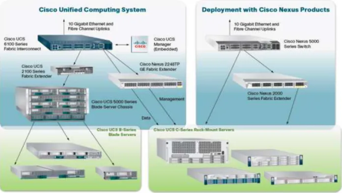
The Cisco UCS components are shown in the diagram below.21
Figure 3: Cisco UCS Components
The Cisco Unified Computing System is designed from the ground up to be programmable and self- integrating. A server’s entire hardware stack, ranging from server firmware and settings to network profiles, is configured through model-based management. With Cisco virtual interface cards, even the number and type of I/O interfaces is programmed dynamically, making every server ready to power any workload at any time.
With model-based management, administrators manipulate a model of a desired system configuration then associate a model’s service profile with hardware resources. Once associated the system
configures itself to match the model. This automation speeds provisioning and workload migration with accurate and rapid scalability. The result is increased IT staff productivity, improved compliance, and reduced risk of failures due to inconsistent configurations.
Cisco Fabric Extender technology reduces the number of system components to purchase, configure, manage, and maintain by condensing three network layers into one. It eliminates both blade server and hypervisor-based switches by connecting fabric interconnect ports directly to individual blade servers and virtual machines. Virtual networks are now managed exactly as physical networks are, but with massive scalability. This represents a radical simplification over traditional systems, reducing capital and operating costs while increasing business agility, simplifying and speeding deployment, and improving performance.
22
5.1.2.
Cisco Fabric Interconnects
The Cisco UCS 6200 Series Fabric Interconnects are a core part of the Cisco Unified Computing System, providing both network connectivity and management capabilities for the system (Figure 2). The Cisco UCS 6200 Series offers line-rate, low-latency, lossless 10 Gigabit Ethernet, Fiber Channel over Ethernet (FCoE), and Fiber Channel functions.
The Cisco UCS 6200 Series provides the management and communication backbone for the Cisco UCS B -Series Blade Servers and 5100 -Series Blade Server Chassis. All chassis, and therefore all blades, attached to the Cisco UCS 6200 Series Fabric Interconnects become part of a single, highly available management domain. In addition, by supporting unified fabric, the Cisco UCS 6200 Series provides both the LAN and SAN connectivity for all blades within its domain.
From a networking perspective, the Cisco UCS 6200 Series uses a cut-through architecture, supporting deterministic, low-latency, line-rate 10 Gigabit Ethernet on all ports, switching capacity of 2 terabits (Tb), and 320-Gbps bandwidth per chassis, independent of packet size and enabled services. The product family supports Cisco® low-latency, lossless 10 Gigabit Ethernet unified network fabric capabilities, which increase the reliability, efficiency, and scalability of Ethernet networks. The fabric interconnect supports multiple traffic classes over a lossless Ethernet fabric from the blade through the Interconnect. Significant TCO savings come from an FCoE-optimized server design in which network interface cards (NICs), host bus adapters (HBAs), cables, and switches can be consolidated.
The Cisco UCS 6248UP is a 48-port Fabric Interconnect which provides low-latency throughput in excess of 1Tbps in a single rack unit (1 RU) form-factor. The Interconnect itself has 32 fixed ports of Fiber Channel, 10-Gigabit Ethernet, Cisco Data Center Ethernet, and FCoE SFP+ ports. One expansion module slot can provide an additional sixteen ports of Fiber Channel, 10-GE, Cisco Data Center Ethernet, and FCoE SFP+.
5.1.3.
Cisco IO Modules (Fabric Extenders)
The Cisco UCS 2200 Series FEX is responsible for multiplexing and forwarding all traffic from blade servers in a chassis to a parent Cisco UCS Fabric Interconnect over the 10-Gbps unified fabric links. All traffic, even traffic between blades on the same chassis, or VMs on the same blade, is forwarded to the parent interconnect, where network profiles are managed efficiently and effectively by the Fabric Interconnect. At the core of the Cisco UCS Fabric Extenders are ASIC processors developed by Cisco to multiplex all traffic.
Note: Up to two fabric extenders can be placed in a blade chassis.
Cisco UCS 2204 used in this architecture has eight 10GBASE-KR connections to the blade chassis mid-plane, with one connection per fabric extender for each of the chassis’ eight half slots. This gives each half-slot blade server access to each of two 10-Gbps unified fabric-based networks through SFP+ sockets for both throughput and redundancy. It has 4 ports connecting up the fabric interconnect.
23
5.1.4.
Cisco UCS Chassis
The Cisco UCS 5108 Series Blade Server Chassis is a 6 RU blade chassis that will accept up to eight half-width Cisco UCS B-Series Blade Servers or up to four full-half-width Cisco UCS B-Series Blade Servers, or a combination of the two. The Cisco UCS 5108 Series Blade Server Chassis can accept four redundant power supplies with automatic load-sharing and failover and two Cisco UCS (either 2100 or 2200 series ) Fabric Extenders. The chassis is managed by Cisco UCS Chassis Management Controllers, which are mounted in the Cisco UCS Fabric Extenders and work in conjunction with the Cisco UCS Manager to control the chassis and its components.
A single Cisco UCS managed domain can theoretically scale to up to 40 individual chassis and 320 blade servers. At this time Cisco supports up to 20 individual chassis and 160 blade servers.
Basing the I/O infrastructure on a 10-Gbps unified network fabric allows the Cisco Unified Computing System to have a streamlined chassis with a simple yet comprehensive set of I/O options. The result is a chassis that has only five basic components:
The physical chassis with passive midplane and active environmental monitoring circuitry Four power supply bays with power entry in the rear, and hot-swappable power supply units
accessible from the front panel
Eight hot-swappable fan trays, each with two fans Two fabric extender slots accessible from the back panel Eight blade server slots accessible from the front panel
5.1.5.
Cisco UCS Manager
The Cisco UCS 6200 Series Fabric Interconnect hosts and runs Cisco UCS Manager in a highly available configuration, enabling the fabric interconnects to fully manage all Cisco UCS elements. Connectivity to the Cisco UCS 5100 Series blade chassis is maintained through the Cisco UCS 2100 or 2200 Series Fabric Extenders in each blade chassis. The Cisco UCS 6200 Series interconnects support out-of-band
management through a dedicated 10/100/1000-Mbps Ethernet management port as well as in-band management. Cisco UCS Manager typically is deployed in a clustered active-passive configuration on redundant fabric interconnects connected through dual 10/100/1000 Ethernet clustering ports.
5.1.6.
Cisco UCS B200 M3Blade Servers
Cisco UCS B200 M3 is a third generation half-slot, two-socket blade server. The Cisco UCS B200 M3 harnesses the power of the latest Intel® Xeon® processor E5-2600 product family, with up to 384 GB of RAM (using 16-GB DIMMs), two optional SAS/SATA/SSD disk drives, and up to dual 4x 10 Gigabit Ethernet throughput, utilizing our VIC 1240 LAN on motherboard (LOM) design. The Cisco UCS B200 M3 further extends the capabilities of Cisco Unififed Computing Sytem by delivering new levels of
manageability, performance, energy efficiency, reliability, security, and I/O bandwidth for enterprise-class virtualization and other mainstream data center workloads.
24
5.1.7.
Cisco Virtual Interface Card (VIC) Converged Network Adapter
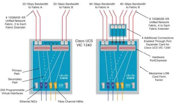
A Cisco innovation, the Cisco UCS Virtual Interface Card (VIC) 1240 (Figure 4) is a 4-port 10 Gigabit Ethernet, Fiber Channel over Ethernet (FCoE)-capable modular LAN on motherboard (mLOM) designed exclusively for the Cisco UCS M3 generation of Cisco UCS B-Series Blade Servers. When used incombination with an optional Port Expander, the Cisco UCS VIC 1240 capabilities can be expanded to eight ports of 10 Gigabit Ethernet.
The Cisco UCS VIC 1240 enables a policy-based, stateless, agile server infrastructure that can present up to 256 PCIe standards-compliant interfaces to the host that can be dynamically configured as either network interface cards (NICs) or host bus adapters (HBAs).
Figure 4: VIC 1240
25
5.2.
EMC VNXe3300
The EMC VNXe series redefines networked storage for the small business to small enterprise user, delivering an unequaled combination of features, simplicity, and efficiency. These unified storage systems provide true storage consolidation capability with seamless management and a unique application-driven approach that eliminates the boundaries between applications and their storage. With scalability from six up to 150 disk drives and 450 terabytes of capacity, the VNXe series is ready to meet the needs of growing organizations with increasingly complex storage requirements. The
VNXe3150TM is an ideal platform for businesses with physical server infrastructures, as well as those making the move to server virtualization to drive consolidation and greater efficiency. The VNXe3300TM includes all of the ease of use and application-driven management features of the VNXe3150, along with increased performance, scalability, and I/O expandability. Both systems share a comprehensive set of features including exceptional capacity utilization, data protection and availability solutions, and advanced support capabilities.
5.2.1.
Advantages and Value Proposition
The EMC VNX™ family is optimized for virtual applications delivering industry-leading innovation and enterprise capabilities for file, block, and object storage in a scalable, easy-to-use solution. This next-generation storage platform combines powerful and flexible hardware with advanced efficiency, management, and protection software to meet the demanding needs of today’s enterprises. The VNXe series is powered by Intel Xeon processor, for intelligent storage that automatically and efficiently scales in performance, while ensuring data integrity and security.
The VNXe series is purpose-built for the IT manager in smaller environments and the VNX series is designed to meet the high-performance, high-scalability requirements of midsize and large enterprises. The table below lists the VNXe customer benefits.
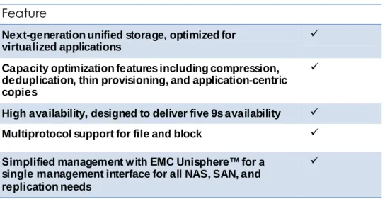
Table 4: VNXe Benefits
Feature
Next-generation unified storage, optimized for virtualized applications
Capacity optimization features including compression, deduplication, thin provisioning, and application-centric copies
High availability, designed to deliver five 9s availability Multiprotocol support for file and block Simplified management with EMC Unisphere™ for a
single management interface for all NAS, SAN, and replication needs
26
5.2.2.
Software suites available
Remote Protection Suite—Protects data against localized failures, outages, and disasters. Application Protection Suite—Automates application copies and proves compliance.
Security and Compliance Suite—Keeps data safe from changes, deletions, and malicious activity.
5.2.3.
Software packs available
Total Value Pack—Includes all three protection software suites and the Security and Compliance Suite
5.3.
Microsoft Technologies
5.3.1.
Windows Server 2012
With Windows Server 2012, Microsoft delivers a server platform built on our experience of building and operating many of the world's largest cloud-based services and datacenter. Whether you are setting-up a single server for your small business or architecting a major new datacenter environment, Windows Server 2012 will help you cloud-optimize your IT so you can fully meet your organization's unique needs.
5.3.1.1.
Beyond Virtualization
Offers a dynamic, multitenant infrastructure to help you scale and secure workloads and build a private cloud. Windows Server 2012 can help you provide:
Complete Virtualization Platform - A fully-isolated, multitenant environment with tools that can help guarantee service level agreements, enable usage-based chargeback, and support self-service delivery.
Improved Scalability and Performance - A high-density, scalable environment that you can modify to perform at an optimum level based on your needs.
Connecting to Cloud Services - A common identity and management framework to enable highly secure and reliable cross-premises connectivity.
5.3.1.2.
The Power of Many Servers, the Simplicity of One
Windows Server 2012 delivers a highly available and easy to manage cloud-optimized platform. Windows Server 2012 can help you provide:
Flexible Storage - Diverse storage choices that can help you achieve high performance, availability, and storage resource efficiency through virtualization and storage
conservation.
Continuous Availability - New and improved features that provide cost-effective, highly available services with protection against a wide range of failure scenarios.
Management Efficiency - Automation of a broad set of management tasks and simplified deployment of workloads as you move toward full, lights-out automation.
27
5.3.1.3.
Every App, Any Cloud
Microsoft Windows Server 2012 offers a cloud-optimized server platform that gives you the flexibility to build and deploy applications and websites on-premises, in the cloud, or across both. Windows Server 2012 can help you deliver:
Flexibility to Build On-Premises and in the Cloud - A consistent set of tools and frameworks that enables developers to build symmetrical or hybrid applications across the datacenter and the cloud.
A Scalable and Elastic Infrastructure - New features to help you increase website density and efficiency, plus frameworks, services, and tools to increase the scalability and elasticity of modern applications.
An Open Web and App Development Environment - An open platform that enables mission-critical applications and provides enhanced support for open standards, open-source applications, and various development languages
5.3.2.
Failover Clustering
Failover clusters provide high availability and scalability to many server workloads. These include server applications such as Microsoft Exchange Server, Hyper-V, Microsoft SQL Server, and file servers. The server applications can run on physical servers or virtual machines. In a failover cluster, if one or more of the clustered servers (nodes) fails, other nodes begin to provide service (a process known as failover). In addition, the clustered roles are proactively monitored to verify that they are working properly. If they are not working, they restart or move to another node. Failover clusters also provide Cluster Shared Volume (CSV) functionality that provides a consistent, distributed namespace that clustered roles can use to access shared storage from all nodes.
5.3.3.
Clustered Shared Volumes
Cluster Shared Volumes (CSVs) in a Windows Server 2012 failover cluster allow multiple nodes in the cluster to simultaneously have read-write access to the same LUN (disk) that is provisioned as an NTFS volume. With CSVs, clustered roles can fail over quickly from one node to another node without
requiring a change in drive ownership, or dismounting and remounting a volume. CSVs also help simplify managing a potentially large number of LUNs in a failover cluster.
CSVs provide a general-purpose, clustered file system in Windows Server 2012, which is layered above NTFS. They are not restricted to specific clustered workloads. (In Windows Server 2008 R2, CSVs only supported the Hyper-V workload.) CSV applications include:
Clustered virtual hard disk (VHD) files for clustered Hyper-V virtual machines Scale-out file shares to store application data for the Scale-Out File Server role
5.3.4.
Networking Support
Windows Server 2012 makes it as straightforward to manage an entire network as a single server, giving you the reliability and scalability of multiple servers at a lower cost. Automatic rerouting around storage, server, and network failures enables file services to remain online with minimal noticeable downtime.
28
Plus Windows Server 2012 – together with System Center 2012 SP1 – provides an end-to-end Software Defined Networking solution across public, private, and hybrid cloud implementations.
Whatever your organization’s needs, be it administering network assets to managing an extensive private and public cloud network infrastructure, Windows Server 2012 offers you solutions to today’s changing business landscape.
5.3.5.
Hyper-V
Windows Server 2012 with Hyper-V is a virtualization platform that has helped organizations of all sizes realize considerable cost savings and operational efficiencies. With industry leading size and scale, Hyper-V is the platform of choice for you to run your mission critical workloads.
Hyper-V in Windows Server 2012 greatly expands support for host processors and memory. It now includes support for up to 64 processors and 1 terabyte of memory for Hyper-V guests, a new VHDX virtual hard disk format with larger disk capacity of up to 64 terabytes, and additional resilience.
Using Windows Server 2012 with Hyper-V, you can take advantage of new hardware technology, while still utilizing the servers you already have. This way you can virtualize today, and be ready for the future.
Whether you are looking to help increase VM mobility, help increase VM availability, handle multi-tenant environments, gain bigger scale, or gain more flexibility, Windows Server 2012 with Hyper-V gives you the platform and tools you need to increase business flexibility with confidence. And you get the portability you need to virtualize on premises or extend your datacenter out to a hosting providing, helping you transform your datacenter into a cloud computing environment.
5.3.6.
Hyper-V Server 2012
Microsoft Hyper-V Server 2012 is a hypervisor-based server virtualization product that enables you to consolidate workloads, helping organizations improve server utilization and reduce costs.
Hyper-V Server is a dedicated stand-alone product that contains the hypervisor, Windows Server driver model, virtualization capabilities, and supporting components such as failover clustering, but does not contain the robust set of features and roles as the Windows Server operating system. As a result Hyper-V Server produces a small footprint and and requires minimal overhead. Organizations consolidating servers where no new Windows Server licenses are required or where the servers being consolidated are running an alternative OS may want to consider Hyper-V Server.
One of the most common uses for Hyper-V Server is in Virtual Desktop Infrastructure (VDI)
environments. VDI allows a Windows client operating system to run on server-based virtual machines in the datacenter, which the user can access from a PC, thin client, or other client device. A full client environment is virtualized within a server-based hypervisor, centralizing users’ desktops.
5.3.7.
SQL Server 2012
Microsoft® SQL Server™ is a database management and analysis system for e-commerce,
line-of-business, and data warehousing solutions. SQL Server 2012, the latest version, adds new high availability and disaster recovery solutions through AlwaysOn clusters and availability groups, xVelocity in-memory storage for extremely fast query performance, rapid data exploration and scalable business intelligence
29
through Power View and tabular modeling in Analysis Services, and new data management capability with Data Quality Services.
5.3.7.1.
AlwaysOn Application Groups
The AlwaysOn Availability Groups feature is a high-availability and disaster-recovery solution that provides an enterprise-level alternative to database mirroring. Introduced in SQL Server 2012, AlwaysOn Availability Groups maximizes the availability of a set of user databases for an enterprise. An availability group supports a failover environment for a discrete set of user databases, known as availability
databases, that fail over together. An availability group supports a set of read-write primary databases and one to four sets of corresponding secondary databases. Optionally, secondary databases can be made available for read-only access and/or some backup operations.
5.3.8.
System Center Virtual Machine Manager 2012 SP1
Microsoft System Center 2012 provides a common management toolset to help you configure, provision, monitor, and operate your IT infrastructure. If your infrastructure is like that of most organizations, you have physical and virtual resources running heterogeneous operating systems. The integrated physical, virtual, private, and public cloud management capabilities in System Center 2012 can help ensure efficient IT management and optimized ROI of those resources.
Virtual Machine Manager (VMM) is a management solution for the virtualized datacenter, enabling you to configure and manage your virtualization host, networking, and storage resources in order to create and deploy virtual machines and services to private clouds that you have created.
Virtual Machine Manager uses a single pane of glass to manage multi-hypervisor virtualized
environments such as Windows Server Hyper-V, Citrix XenServer, and VMware vSphere. This enables you to extend existing investments while you build your private cloud.
5.4.
Citrix XenDesktop 7
5.4.1.
Enhancements in This Release
Built on the Avalon™ architecture, Citrix XenDesktop™ 7 includes significant enhancements to help customers deliver Windows apps and desktops as mobile services while addressing management complexity and associated costs. Enhancements in this release include:
A new unified product architecture—the FlexCast 2.0 architecture— and administrative interfaces designed to deliver both hosted-shared applications (RDS) and complete virtual desktops (VDI). Unlike previous software releases that required separate Citrix XenApp farms and XenDesktop infrastructures, this new release allows administrators to deploy a single infrastructure and employ a consistent set of management tools for mixed desktop and app workloads.
New and improved management interfaces. XenDesktop 7 includes two new purpose-built management consoles—one for automating workload provisioning and app publishing and the second for real-time monitoring of the infrastructure.
30
Enhanced HDX technologies. Since mobile technologies and devices are increasingly pervasive, Citrix has engineered new and improved HDX technologies to improve the user experience for hosted Windows apps and desktops delivered on laptops, tablets, and smartphones.
Unified App Store. The release includes a self-service Windows app store, implemented through Citrix StoreFront services, that provides a single, simple, and consistent aggregation point for all user services. IT can publish apps, desktops, and data services to the StoreFront, from which users can search and subscribe to services.
5.4.2.
FlexCast Technology
In Citrix XenDesktop 7, FlexCast 2.0 technology is responsible for delivering and managing hosted-shared RDS apps and complete VDI desktops. By using Citrix Receiver with XenDesktop 7, users have a device-native experience on endpoints including Windows, Mac, Linux, iOS, Android, ChromeOS, and
Blackberry.
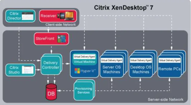
The diagram below shows an overview of the unified FlexCast 2.0 architecture and underlying components, which are also described below:
Citrix Receiver. Running on user endpoints, Receiver provides users with self-service access to resources published on XenDesktop servers. Receiver combines ease of deployment and use, supplying fast, secure access to hosted applications, desktops, and data. Receiver also provides on-demand access to Windows, Web, and Software-as-a-Service (SaaS) applications.
Citrix StoreFront. StoreFront authenticates users and manages catalogs of desktops and applications. Users can search StoreFront catalogs and subscribe to published services through Citrix Receiver.
31
Figure 6: XenDesktop 7 Architecture
Citrix Studio. Using the new and improved Studio interface, administrators can easily configure and manage XenDesktop deployments. Studio provides wizards to guide the process of setting up an environment, creating desktops, and assigning desktops to users, automating provisioning and application publishing. It also allows administration tasks to be customized and delegated to match site operational requirements.
Delivery Controller. The Delivery Controller is responsible for distributing applications and desktops, managing user access, and optimizing connections to applications. Each site has one or more delivery controllers.
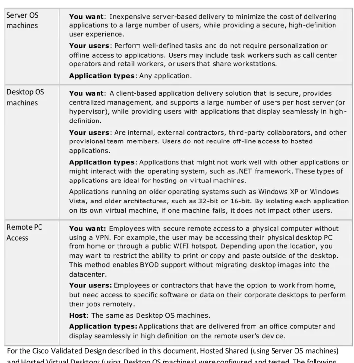
Server OS Machines. These are virtual or physical machines (based on a Windows Server operating system) that deliver RDS applications or hosted shared desktops to users. Desktop OS Machines. These are virtual or physical machines (based on a Windows Desktop
operating system) that deliver personalized VDI desktops or applications that run on a desktop operating system.
Remote PC. XenDesktop with Remote PC allows IT to centrally deploy secure remote access to all Windows PCs on the corporate network. It is a comprehensive solution that delivers fast, secure remote access to all the corporate apps and data on an office PC from any device. Virtual Delivery Agent. A Virtual Delivery Agent is installed on each virtual or physical machine
(within the server or desktop OS) and manages each user connection for application and desktop services. The agent allows OS machines to register with the Delivery Controllers and governs the HDX connection between these machines and Citrix Receiver.
32
Citrix Director. Citrix Director is a powerful administrative tool that helps administrators quickly troubleshoot and resolve issues. It supports real-time assessment, site health and performance metrics, and end user experience monitoring. Citrix EdgeSight® reports are available from within the Director console and provide historical trending and correlation for capacity planning and service level assurance.
Citrix Provisioning Services 7. This new release of Citrix Provisioning Services (PVS) technology is responsible for streaming a shared virtual disk (vDisk) image to the configured Server OS or Desktop OS machines. This streaming capability allows VMs to be provisioned and
re-provisioned in real-time from a single image, eliminating the need to patch individual systems and conserving storage. All patching is done in one place and then streamed at boot-up. Citrix PVS 7 supports image management for both RDS and VDI-based machines, including support for image snapshots and rollbacks.
5.4.3.
High-Definition User Experience (HDX) Technology
High-Definition User Experience (HDX) technology in this release is optimized to improve the user experience for hosted Windows apps on mobile devices. Specific enhancements include:
HDX Mobile™ technology, designed to cope with the variability and packet loss inherent in today’s mobile networks. HDX technology supports deep compression and redirection, taking advantage of advanced codec acceleration and an industry-leading H.264-based compression algorithm. The technology enables dramatic improvements in frame rates while requiring significantly less bandwidth. HDX technology offers users a rich multimedia experience and optimized performance for voice and video collaboration.
HDX Touch technology enables mobile navigation capabilities similar to native apps, without rewrites or porting of existing Windows applications. Optimizations support native menu controls, multi-touch gestures, and intelligent sensing of text-entry fields, providing a native application look and feel.
HDX 3D Pro uses advanced server-side GPU resources for compression and rendering of the latest OpenGL and DirectX professional graphics apps. GPU support includes both dedicated user and shared user workloads.
5.4.4.
Citrix XenDesktop 7 Desktop and Application Services
IT departments strive to deliver application services to a broad range of enterprise users that have varying performance, personalization, and mobility requirements. Citrix XenDesktop 7 allows IT to configure and deliver any type of virtual desktop or app, hosted or local, and optimize delivery to meet individual user requirements, while simplifying operations, securing data, and reducing costs.
33
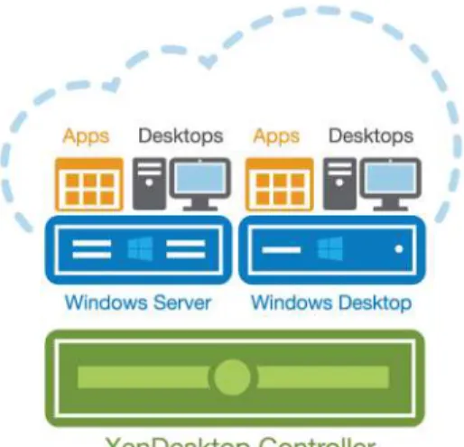
Figure 7: XenDesktop Controller
With previous product releases, administrators had to deploy separate XenApp farms and XenDesktop sites to support both hosted-shared RDS and VDI desktops. As shown above, the new XenDesktop 7 release allows administrators to create a single infrastructure that supports multiple modes of service delivery, including:
Application Virtualization and Hosting (RDS). Applications are installed on or streamed to Windows servers in the data center and remotely displayed to users’ desktops and devices. Hosted Shared Desktops (RDS). Multiple user sessions share a single, locked-down Windows Server environment running in the datacenter and accessing a core set of apps. This model of service delivery is ideal for task workers using low intensity applications, and enables more desktops per host compared to VDI.
Pooled VDI Desktops. This approach leverages a single desktop OS image to create multiple thinly provisioned or streamed desktops. Optionally, desktops can be configured with a Personal vDisk to maintain user application, profile and data differences that are not part of the base image. This approach replaces the need for dedicated desktops, and is generally deployed to address the desktop needs of knowledge workers that run more intensive application workloads.
VM Hosted Apps (16 bit, 32 bit, or 64 bit Windows apps). Applications are hosted on virtual desktops running Windows 7, XP, or Vista and then remotely displayed to users’ physical or virtual desktops and devices.
This Cisco Validated Design focuses on delivering a mixed workload consisting of hosted shared desktops (RDS) and pooled VDI desktops.
5.4.5.
Provisioning Services 7
One significant advantage to service delivery through RDS and VDI is how these technologies simplify desktop administration and management. Citrix Provisioning Services (PVS) takes the approach of streaming a single shared virtual disk (vDisk) image rather than provisioning and distributing multiple OS