http://www.scirp.org/journal/ojce ISSN Online: 2164-3172 ISSN Print: 2164-3164
Interaction of Twin Circular Shallow Tunnels
in Soils—Parametric Study
Faisal I. Shalabi
Department of Civil & Environmental Engineering, King Faisal University, Al-Ahssa, Kingdom of Saudi Arabia
Abstract
In big and crowded cities with limited urban areas, it is sometimes necessary to build twin tunnels to overcome transportation problems. In a city like Riyadh in Saudi Arabia, tunneling becomes very essential to solve effectively traffic conjunctions and associated problems. The city started to construct big tunneling projects and it is expected in the near future to start building twin tunnels. If the design and construction process of twin tunnels are not un-derstood and considered, damage to the tunnel lining or excessive ground surface settlement may take place. In this study, the interaction between adja-cent tunnels excavated through soils in Saudi Arabia has been investigated using FE analysis and the range of the encountered soil properties. The inves-tigation considered the effect of spacing between the twin tunnels and ground conditions on tunnel behavior. The analysis focused on the effect of con-structing twin tunnels on ground surface settlement, contact pressure between lining and ground, and change in tunnel diameter. Based on the results ob-tained, it was observed that as the compressibility ratio, c, and spacing be-tween tunnels decreased, the interaction effect bebe-tween tunnels increased. For compressibility ratio of 0.01, the excavation of the new tunnel caused an in-crease in the lining deformation of the old one in the range of 0.1% to 0.3%. Furthermore, the excavation of the new tunnel leads to an increase in the contact pressure at the crown of the old one by 7% - 9%. At the spring line level, the excavation of the new tunnel had almost no effect on the far side of the old one. On the other hand, and for low compressibility ratio, the new tunnel excavation significantly affected contact pressure at the near side of the old one. For an expected tunnel life of 100 years, the results show an increase in the normalized contact pressure at the crown of the old tunnel due to the excavation of the new one in the range of 2% - 7% for compressibility ratio ranging between 0.01 - 0.1, respectively.
Keywords
Twin Tunnels, FE Analysis, Settlement, Deformation, Contact Pressure
How to cite this paper: Shalabi, F.I. (2017) Interaction of Twin Circular Shallow Tun-nels in Soils—Parametric Study. Open Jour-nal of Civil Engineering, 7, 100-115. https://doi.org/10.4236/ojce.2017.71006
Received: February 3, 2017 Accepted: March 17, 2017 Published: March 20, 2017
Copyright © 2017 by author and Scientific Research Publishing Inc. This work is licensed under the Creative Commons Attribution International License (CC BY 4.0).
1. Introduction
In large and crowded cities, the transportation system is a critical issue. Nowa-days, countries pay much attention to the transportation system because it re-flects their development and success. As the surface area in cities gets limited and is very expensive to develop new infrastructures for roads and rails, the need for underground tunnels to generate an effective and sustainable transportation system becomes crucial. Special care needs to be considered when constructing tunnels underneath cities because any failure could be catastrophic especially when tunneling through soils or weak rocks. During tunnel construction or even after construction (in squeezing ground), ground movement may lead to surface settlement which in turn may affect the super structures. During the last 70 years, many researchers studied and investigated single tunneling behavior and its effect on the surrounding structures (e.g. Terzaghi [1]; Morgan [2]; Peck [3]; Deere et al. [4]; Cording et al. [5]; Peck et al. [6]; Kulhawy [7]; Wood [8]; Eins-tein [9]; Ranken et al. [10]; Bieniawski [11]; Penzien [12]; Shalabi [13] [14]; Sha-labi et al. [15] [16] [17] [18]).
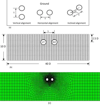
In order to minimize the cost of constructing a large diameter transportation tunnel especially in areas where ground conditions are expected to produce large deformations, constructing twin or adjacent tunnels is preferable. Twin tunnels may be constructed with horizontal, vertical, or inclined alignment as shown in
Figure 1(a).
Many investigators studied the interaction between tunnels and its effect on ground movement. Tsuchiyama et al. [19] used 3D finite element method ap-proach to analyze the interaction at the intersection of a new access tunnel with an existing main tunnel in rock. They found that the influence zone around the main tunnel was in the order of 1D to 3D of the tunnel diameter (where D is tunnel diameter). Kim et al. [20] [21], based on tests on closely spaced tunnels excavated in clay, found that spring line and crown of the existed tunnel are the most affected parts. Liu et al. [22] studied the influence of excavating a new tun-nel in rock on the support system of an existing tuntun-nel using 3D FEM (Finite element method) and elasto-plastic material models. They found that the influ-ence of the new tunnel on the supporting system of the existing tunnel is signifi-cant when the face of the new one passes the support system of the old one. Do
S
40 D 10 D
2.5 D
LFT RGT
S S
S
Ground
β
Horizontal alignment
Vertical alignment Inclined alignment
S (a)
(b)
[image:3.595.212.536.74.415.2](c)
Figure 1. (a) Twin tunnels configuration, (b) used tunnel geometry for the analysis, & (c) FE-Mesh.
established a relation between a non-dimensional stability number (function of soil cover, cohesion, and unit weight) and the tunnels spacing for different tun-nel diameter and soil properties. Fang et al. [26] presented a case of closely twin tunnels constructed beneath closely spaced twin tunnels. Their results showed that the trough of the ground surface settlement displayed a “W” shape, while after constructing the new twin tunnels the trough surface settlement displayed the “U” shape. Fargnoli et al. [27] studied the surface and structural settlement due to excavation of Milan metro twin tunnel through coarse grained soils. The results showed that the second tunnel resulted in an increase in settlement at the surface of the first tunnel.
2. Numerical Modeling
2D Visco-elastic model was used to perform the analysis. The soil material engi-neering properties were selected to cover the soil properties encountered in Sau-di Arabia. Power law creep model was used to simulate the viscous behavior of the selected soils. This model describes the relationship between the strain rates, stress, and time according to the following formula:
n m
A t
ε= σ (1) where
ε
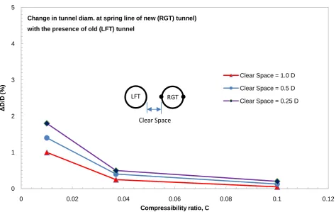
is the stain rate, σ is the stress difference, t is the time, A, m, and n arethe creep model parameters and they depend on the temperature. According to Ouyang [29] and to have reasonable results, A and n should be positives, and m needs to be between −1.0 and 0.0. Power law creep model is available in ABAQUS software and can be used directly for time dependent analysis. Table 1 shows the used concrete lining properties and encountered soil properties for shallow tunneling in Saudi Arabia.
3. Simulation of Loading and Excavation Process
Figure 1(b) & Figure 1(c) show the geometrical arrangement and FE mesh of the analyzed tunnels. In this case, circular cross-section tunnels with diameters of 10.0 m and thickness of 0.5 m were excavated at a depth of 25 m from the ground surface to the tunnel center and with different spacing, s. The analyses were performed using ABAQUS FE software through step analysis. The gravity loads were applied first throughout the whole model. The excavation process in-side the tunnel was simulated by removing the inner soil elements of the left (old) lining, then erecting its lining by activating the concrete elements. The right (new) tunnel was built in subsequent steps using the same procedures as of the left tunnel. Time dependent behavior was introduced at later steps using power law creep model for a tunnel lifetime of 100 years.
4. Results and Discussion
4.1. Ground Surface Settlement
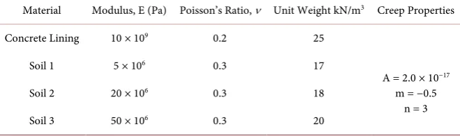
[image:4.595.208.538.637.735.2]Ground surface settlement above the centerline of right tunnel (new) when ex-cavated with the presence of the left (old) tunnel is shown in Figure 2. The compressibility ratio, which correlates the relative stiffness between the ground medium and tunnel lining, was evaluated based on Peck et al. [6] equation:
Table 1. Concrete lining and soil properties.
Creep Properties Unit Weight kN/m3
Poisson’s Ratio, ν
Modulus, E (Pa) Material
25 0.2
10 × 109 Concrete Lining
A = 2.0 × 10⁻¹⁷ m = −0.5
n = 3 17
0.3 5 × 10⁶
Soil 1
18 0.3
20 × 106 Soil 2
20 0.3
Figure 2. Ground surface settlement above the C.L. of new (RGT) tunnel with the presence of the old (LFT) one.
(
)
(
)(
)
2 1
1 1 2
m l
l m m
E v R
c
E t v v
− =
+ − (2)
where El, vl, R, and t are the lining modulus of elasticity, Poisson’s ratio, radius,
and thickness, respectively, and Em and vm are the ground medium modulus of
elasticity and Poisson’s ratio, respectively.
In this figure, it can be seen that as the compressibility ratio increases, the surface settlement increases. This effect becomes almost negligible for compres-sibility ratio greater than 0.04. In addition, this figure shows that as the spacing between the twin tunnels decreases, the ground surface settlement increases. The effect of spacing on surface settlement is also negligible for compressibility ratio greater than 0.04. Figure 3 shows the effect of excavation of right (new) tunnel on ground surface settlement above the centerline of left (old) tunnel. In this figure, the increase in the surface settlement is between 25% - 30% for compres-sibility ratio of 0.01 and the effect on surface settlement decreases as both the compressibility ratio and the spacing between the twin tunnels decreases.
4.2. Lining Deformation
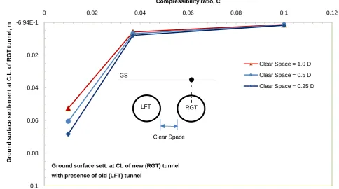
Tunnel lining deformation (∆D/D) of the right (new) tunnel with the presence
of the left (old) tunnel at the crown and spring line shows increasing values with the decrease in compressibility ratio, c, as shown in Figure 4 and Figure 5 re-spectively. In these figures, the results show that the change in tunnel diameter is in the range of 1% to 2% for compressibility ratio of about 0.01. The results also indicate that as the spacing between the tunnels decreases, the lining deformation
-6.94E-1
0.02
0.04
0.06
0.08
0.1
0 0.02 0.04 0.06 0.08 0.1 0.12
G
round
s
ur
fa
c
e
s
e
tt
le
m
e
nt
a
t
C
.L.
of
R
G
T
t
unne
l,
m
Compressibility ratio, C
Ground surface sett. at CL of new (RGT) tunnel with presence of old (LFT) tunnel
Clear Space = 1.0 D
Clear Space = 0.5 D
Clear Space = 0.25 D
Clear Space GS
Figure 3. Increase in ground surface settlement above the C.L. of the old (LFT) tunnel due to the excavation of the new (RGT) one.
Figure 4. Change in tunnel diameter at crown of new (RGT) tunnel with the presence of the old (LFT) one. 0
0.01
0.02
0.03
0.04
0.05
0 0.02 0.04 0.06 0.08 0.1 0.12
Inc
re
a
s
e
i
n
gr
ound s
ur
fa
c
e
s
e
tt
le
m
e
nt
a
t
C
.L.
of
LFT
t
unne
l,
m
Compressibility ratio, C
Increase in ground surface sett. of CL of LFT Tunnel
due to excavation of new (RGT) tunnel
Clear Space = 1.0 D
Clear Space = 0.5 D
Clear Space = 0.25 D
Clear Space
LFT RGT
GS
0 1 2 3 4 5
0 0.02 0.04 0.06 0.08 0.1 0.12
Δ
D/
D
(%
)
Compressibility ratio, C Change in Tunnel Diam. at Crown-Invert of RGT Tunnel
with presence of LFT tunnel
Clear Space = 1.0 D
Clear Space = 0.5 D
Clear Space = 0.25 D Clear Space
[image:6.595.60.534.419.713.2]Figure 5. Change in tunnel diameter at spring line of the new (RGT) with the presence of the old (LFT) one.
increases and these deformation are almost negligible for compressibility ratio, c greater than 0.04. Considering the effect of new tunnel excavation on the defor-mation of the old one, Figure 6 and Figure 7 show that there is an increase in lining deformation in the range of 0.1% to 0.3% for compressibility ratio of 0.01. Moreover, those figures show that lining deformation decreases as the spacing between the tunnels increases.
4.3. Lining-Ground Contact Pressure
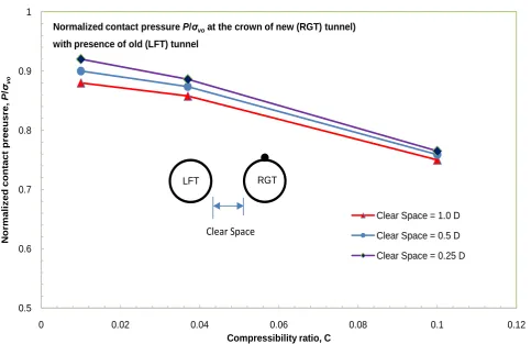
Lining contact pressure, P, normalized to the overburden pressure at the crown (σvo) of the right (new) tunnel shows a decrease in the value as the
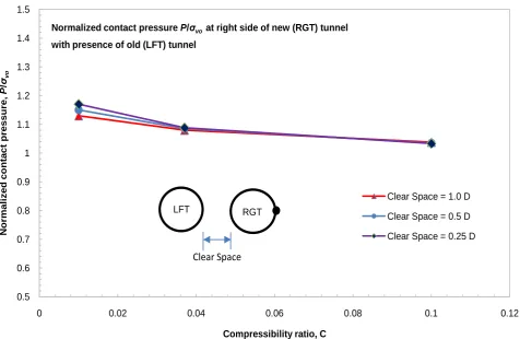
compressibil-ity ratio increases, as shown in Figure 8. It can be noticed that the normalized contact pressure is within the range of 0.86 to 0.92 for compressibility ratio of 0.01. For the left (old) tunnel, the normalized contact pressure is higher than that of the right (new) one and it is in the range of 0.92 - 1.0, as shown in Figure 9. This indicates that, due to the excavation of the new tunnel there was an in-crease in the contact pressure at the crown of the old tunnel in the range of 7% - 9% for compressibility ratio of 0.01. At the spring lines of the two tunnels, the results of normalized contact pressure show different and interested observa-tions, as can be seen in Figure 10 through Figure 13. For the right (new) tunnel, the contact pressure (P) normalized to the overburden pressure at the spring line level (σvo) is almost identical for both sides, as can be seen in Figure 10 and Figure 11, and it is in the range of 1.12 - 1.20 for compressibility ratio, c of 0.01.
0 1 2 3 4 5
0 0.02 0.04 0.06 0.08 0.1 0.12
Δ
D/
D
(%
)
Compressibility ratio, C Change in tunnel diam. at spring line of new (RGT) tunnel)
with the presence of old (LFT) tunnel
Clear Space = 1.0 D
Clear Space = 0.5 D
Clear Space = 0.25 D
Clear Space
L
Figure 6. Increase in tunnel diameter change at the crown of the old (LFT) tunnel due to the excavation of the new (RGT) one.
Figure 7. Increase in tunnel diameter change at the spring line of the old (LFT) tunnel due to the excavation of the new (RGT) one. 0
0.1 0.2 0.3 0.4 0.5 0.6 0.7 0.8 0.9 1
0 0.02 0.04 0.06 0.08 0.1 0.12
Δ
D/
D
(%
)
Compressibilty ratio, C
Additional change in Tunnel Diam. at Crown-Invert of old (LFT) tunnel
Due to excavation of new (RGT) Tunnel
Clear Space = 1.0 D
Clear Space = 0.5 D
Clear Space = 0.25 D RGT
Clear Space LFT
0 0.1 0.2 0.3 0.4 0.5 0.6 0.7 0.8 0.9 1
0 0.02 0.04 0.06 0.08 0.1 0.12
Δ
D/
D
(%
)
Compressibility ratio, C Additional change in tunnel diam. at spring line of old (LFT) tunnel due to excavation of new (RGT) tuunel
Clear Space = 1.0 D
Clear Space = 0.5 D
Clear Space = 0.25 D Clear Space
[image:8.595.64.536.385.715.2]Figure 8. Normalized contact pressure at the crown of the new (RGT) tunnel with the presence of the old (LFT) one.
Figure 9. Normalized contact pressure at the crown of the old (LFT) tunnel after excavating the new (RGT) one. 0.5
0.6 0.7 0.8 0.9 1
0 0.02 0.04 0.06 0.08 0.1 0.12
N
o
rm
al
iz
ed
co
n
tact
p
reeu
sr
e
,
P
/σ
vo
Compressibility ratio, C Normalized contact pressure P/σvoat the crown of new (RGT) tunnel)
with presence of old (LFT) tunnel
Clear Space = 1.0 D
Clear Space = 0.5 D
Clear Space = 0.25 D Clear Space
LFT RGT
0.7 0.8 0.9 1
0 0.02 0.04 0.06 0.08 0.1 0.12
N
o
rm
al
iz
ed
co
n
tact
p
ressu
re,
P
/σ
vo
Compressibility ratio, C Normalized contact pressure P/σvoat crown of old(LFT) tunnel
after excavating the new (RGT) tunnel
Clear Space = 1.0 D
Clear Space = 0.5 D
Clear Space = 0.25 D Clear Space
[image:9.595.61.536.407.713.2]Figure 10. Normalized contact pressure at the right side of the new (RGT) tunnel with the presence of the old (LFT) one.
Figure 11. Normalized contact pressure at the left side of the new tunnel (RGT) with the presence of the old (LFT) one. 0.5
0.6 0.7 0.8 0.9 1 1.1 1.2 1.3 1.4 1.5
0 0.02 0.04 0.06 0.08 0.1 0.12
N
o
rm
al
iz
ed
co
n
tact
p
ressu
re,
P
/σ
vo
Compressibility ratio, C Normalized contact pressure P/σvoat right side of new (RGT) tunnel
with presence of old (LFT) tunnel
Clear Space = 1.0 D
Clear Space = 0.5 D
Clear Space = 0.25 D
Clear Space
LFT RGT
0.5 0.6 0.7 0.8 0.9 1 1.1 1.2 1.3 1.4 1.5
0 0.02 0.04 0.06 0.08 0.1 0.12
N
o
rm
al
iz
ed
co
n
tact
p
ressu
re,
P
/σ
vo
Compressibility ratio, C Normalized contact pressure P/σvoat left side of new (RGT) tunnel
with presence of old (LFT) tunnel
Clear Space = 1.0 D
Clear Space = 0.5 D
Clear Space = 0.25 D
Clear Space
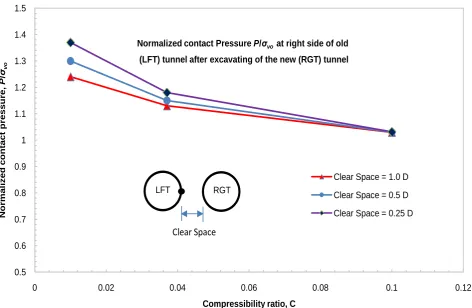
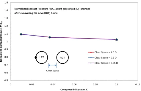
[image:10.595.64.532.410.717.2]The values of normalized contact pressure decrease with c and become almost in the range of 1.02 - 1.06 for c greater than 0.04. For the left (old) tunnel, the re-sults in Figure 12 and Figure 13 show that the normalized contact pressure at the side close to the new tunnel is higher (ranges between 1.24 - 1.38) than that at the opposite side (value is equal to 1.1) for compressibility ratio of 0.01. In ad-dition to that, the close side of the old tunnel shows a decrease in the contact pressure with the compressibility ratio, and for c equal to 0.1, the new tunnel has no effect on the normalized contact pressure, and the value is almost constant and equal to 1.1.
4.4. Time Dependent Behavior
[image:11.595.64.537.407.715.2]Time dependent behaver of the increase in normalized contact pressure at the crown of the left (old) tunnel due to the excavation of the right (new) tunnel is found to be decreases with both, the increase in compressibility ratio and the spacing between the twin tunnels, as shown in Figure 14 through Figure 16. As can be seen in these figures, the increase in the normalized contact pressure on the crown of the old tunnel lining increases with time in a decreasing rate, and it starts to level of after almost 10 years. For an expected tunnel life of 100 years, the increase in the normalized contact pressure with tunnel spacing is almost equal, and it is in the range of 2% to 7% for compressibility ratio ranging be-tween 0.01 and 0.1, respectively.
Figure 12. Normalized contact pressure at the right side of the old (LFT) tunnel after excavating the new (RGT) one. 0.5
0.6 0.7 0.8 0.9 1 1.1 1.2 1.3 1.4 1.5
0 0.02 0.04 0.06 0.08 0.1 0.12
N
o
rm
al
iz
ed
co
n
tact
p
ressu
re,
P
/σ
vo
Compressibility ratio, C
Normalized contact Pressure P/σvoat right side of old
(LFT) tunnel after excavating of the new (RGT) tunnel
Clear Space = 1.0 D
Clear Space = 0.5 D
Clear Space = 0.25 D
Clear Space
Figure 13. Normalized contact pressure at the left side of the old (LFT) tunnel after excavating the new (RGT) one.
Figure 14. Increase in normalized contact pressure vs. time at the crown of theold (LFT) tunnel due to the excavation of the new (RGT) one. c = 0.01.
0.5 0.6 0.7 0.8 0.9 1 1.1 1.2 1.3 1.4 1.5
0 0.02 0.04 0.06 0.08 0.1 0.12
N
o
rm
al
iz
ed
co
n
tact
p
ressu
re,
P
/σvo
Compressibility ratio, C Normalized contact Pressure P/σvoat left side of old (LFT) tunnel after excavating the new (RGT) tunnel
Clear Space = 1.0 D
Clear Space = 0.5 D
Clear Space = 0.25 D
Clear Space
LFT RGT
0.1 1 10
0.001 0.01 0.1 1 10 100
In
cr
ease
in
n
o
rm
al
iz
ed
co
n
tact
p
ressu
re
P
/σ
vo
,
%
Time (Years) Increase in normalized contact pressure at Crown of old (LFT) tunnel lining due to excavation of new (RGT) tunnel.
Clear Space = 1.0 D
Clear Sace = 0.5 D
Clear Space = 0.25 D Clear Space
LFT RGT
[image:12.595.58.537.404.705.2]Figure 15. Increase in normalized contact pressure vs. time at the crown of the old (LFT) tunnel due to the excavation of the new (RGT) one. c = 0.037.
Figure 16. Increase in normalized contact pressure vs. time at the crown of the old (LFT) tunnel due to the excavation of the new (RGT) one. c = 0.1.
0.1 1 10
0.001 0.01 0.1 1 10 100
In
cr
ease
in
n
o
rm
al
iz
ed
co
n
tact
p
ressu
re
P
/σ
vo
,
%
Time (Years) Increase in normalized contact pressure at crown of old (LFT)
tunnel lining due to excavation of new (RGT) tunnel.
Clear Space = 1.0 D
Clear Sace = 0.5 D
Clear Space = 0.25 D
Clear Space
LFT RGT
Compressibility ratio, c= 0.037
0.1 1 10
0.001 0.01 0.1 1 10 100
In
cr
ease
in
n
o
rm
al
iz
ed
co
n
tact
p
ressu
re
P
/σ
vo
,
%
Time (Years) Increase in normalized contact pressure at crown of old (LFT)
tunnel lining due to excavation of new (RGT) tunnel.
Clear Space = 1.0 D
Clear Sace = 0.5 D
Clear Space = 0.25 D
Clear Space Compressibility ratio, c= 0.1
[image:13.595.69.535.408.704.2]5. Conclusions
In big and crowded cities, having an efficient and sustainable transportation sys-tem is a big challenge. Transportation tunnels are considered a good solution to this problem. In critical situations, it is sometimes necessary to build new trans-portation tunnels adjacent to old ones. The interaction between the new tunnel and the old one, and their effects on the overall stability in terms of deformation, contact pressure, and ground surface settlement become a real issue. In this study, the interaction between twin tunnels was investigated. The study focused on the ground surface settlement above the centerline of the tunnel, lining de-formation, and lining-ground contact pressure. Based on this study, the follow-ing conclusions are drawn:
1) The interaction between twin tunnels is affected by the compressibility ra-tio and spacing between tunnels. As the compressibility rara-tio and spacing be-tween tunnels decrease, the interaction effect increases.
2) The excavation of the new tunnel leads to an increase in the contact pres-sure at the crown of the old one by 7% - 9%. At the spring line level, the excava-tion of the new tunnel has almost no effect on the far side of the old one. On the other hand, and for low compressibility ratio, the new tunnel excavation signifi-cantly affects the near side of the old one.
3) For compressibility ratio of 0.01, the excavation of the new tunnel causes an increase in lining deformation of the old one in the range of 0.1% to 0.3%.
4) The increase in the ground surface settlement above the centerline of the old tunnel due to the excavation of the new one is between 25% - 30% for com-pressibility ratio of 0.01.
5) For an expected tunnel life of 100 years, the increase in the normalized contact pressure at the crown of the old tunnel due to the excavation of the new one is in the range of 2% to 7% for compressibility ratio ranging between 0.01 and 0.1, respectively.
Acknowledgements
The author would like to thank Engr. Mohammad Al-Nasharti for his help in providing some data about soil properties.
References
[1] Terzaghi, K. (1946) Rock Defects and Loads on Tunnel Supports. In: Proctor, R.V. and White, T.L., Eds., Rock Tunneling with Steel Supports, Commercial Shearing and Stamping Company, Youngstown.
[2] Morgan, H.D. (1961) A Contribution to the Analysis of Stress in a Circular Tunnel.
Geotechnique, 11, 37-46.https://doi.org/10.1680/geot.1961.11.1.37
[3] Peck, R.B. (1969) Deep Excavation and Tunneling in Soft Ground. State of the Art Report. 7th International Conference on Soil Mechanics and Foundation Engineer-ing, Mexico City, 225-290.
[4] Deere, D.U., Peck, R.B., Monsees, J.E., Parker, H.W. and Schmidt, B. (1969) Design of Tunnel Support Systems. Highway Research Record No. 339, 26-33.
Measure-ments. Proceedings of 1st NARETC, Chicago, 601-622.
[6] Peck, R.B., Hendron, A.J. and Mohraz, B. (1972) State of the Art of Soft-Ground Tunneling. International Proceedings of the North American Rapid Excavation and Tunneling Conference, Chicago, 5-7 June 1972, 259-286.
[7] Kulhawy, F.H. (1974) Finite Element Modeling Criteria for Underground Openings in Rock. International Journal of Rock Mechanics and Mining Sciences, 11, 465- 472.https://doi.org/10.1016/0148-9062(74)91996-2
[8] Wood, A.M. (1975) The Circular Tunnel in Elastic Ground. Geotechnique, 25, 115- 127.https://doi.org/10.1680/geot.1975.25.1.115
[9] Einstein, H.H. and Schwartz, C.W. (1979) Simplified Analysis for Tunnel Supports.
Journal of the Geotechnical Engineering Division, 105, 499-517.
[10] Ranken, R.E., Ghaboussi, J. and Hendron, A.J. (1987) Analysis of Ground-Liner In-teraction for Tunnels. Report UMTA-IL-06-0043-78-3. US Department Transporta-tion, Washington DC.
[11] Bieniawski, Z.T. (1989) Engineering Rock Mass Classifications. Wiley, New York. [12] Penzien, J. and Wu, C.L. (1998) Stresses in Linings of Bored Tunnels. Earthquake
Engineering and Structural Dynamics, 27, 283-300.
https://doi.org/10.1002/(SICI)1096-9845(199803)27:3<283::AID-EQE732>3.0.CO;2-T
[13] Shalabi, F.I. (2004) Assessment of Tunnel Design Based on Different Empirical Ap-proaches: Case Study in Jordan. International Conference on Structural and Geo-technical Engineering and Construction Technology, Mansoura, 23-25 March 2004, 1-16.
[14] Shalabi, F. (2005) FE Analysis of Time-Dependent Behavior of Tunneling in Squeezing Ground Using Two Different Creep Models. Tunnelling and Underground Space Technology, 20, 271-279.https://doi.org/10.1016/j.tust.2004.09.001
[15] Shalabi, F.I. and Cording, E.J. (2005) 3D-Finite Element Analysis of Segmental Concrete Tunnel Lining Deformation and Moments under the Effect of Static and Earthquake Loading. Proceeding of the 11th International Conference on Computer Methods and Advances in Geomechanics, Torino, 19-24 June 2005, 75-82.
[16] Shalabi, F., Hussam, A. and Omar, H. (2009) Elasto-Plastic Behavior of Raghadan Tunnel Based on RMR and Hoek-Brown Classification. Geotechnical and Geologi-cal Engineering, 27, 237-248.https://doi.org/10.1007/s10706-008-9225-0
[17] Shalabi, F.I., Cording, E.J. and Paul, S.L. (2012) Concrete Segment Tunnel Lining Sealant Performance under Earthquake Loading. Tunnelling and Underground Space Technology, 31, 51-60.https://doi.org/10.1016/j.tust.2012.04.006
[18] Shalabi, F.I., Cording, E.J. and Paul, S.L. (2016) Sealant Behavior of Gasketed Seg-mental Tunnel Lining-Conceptual Model. Geommechanics and Tunnelling, 9, 345- 355.https://doi.org/10.1002/geot.201500030
[19] Tsuchiyama, S., Hayakawa, T. and Konno, H. (1988) Deformation Behavior of the Tunnel under the Excavation of Crossing Tunnel. Proceeding of the 6th Interna-tional Conference on Numerical Methods in Geomechanics, Innsbruck, April 1988, 1591-1596.
[20] Kim, S., Burd, H. and Milligan, G. (1996) Interaction between Closely Spaced Tun-nels in Clay. Proceedings of International Symposium on Geotechnical Aspects of Underground Construction in Soft Soil Ground, London, April 1996, 543-548. [21] Kim, S., Burd, H. and Milligan, G. (1998) Model Testing of Closely Spaced Tunnels
in Clay. Geotechnique, 48, 375-388.https://doi.org/10.1680/geot.1998.48.3.375
Existing Support Systems in the Sydney Region. Tunnelling and Underground Space Technology, 23, 399-340.https://doi.org/10.1016/j.tust.2007.06.009
[23] Do, N., Dias, D., Oreste, P. and Maigre, I. (2014) Three-Dimensional Numerical Simulation of a Mechanized Twin Tunnels in Soft Ground. Tunnelling and Under-ground Space Technology, 42, 40-51.https://doi.org/10.1016/j.tust.2014.02.001
[24] Chehade F. and Shahrour I. (2008) Numerical Analysis of the Interaction between Twin-Tunnels: Influence of the Relative Position and Construction Procedure.
Tunneling and Underground Space Technology, 23, 210-214.
https://doi.org/10.1016/j.tust.2007.03.004
[25] Saho, J. and Kumar, J. (2013) Stability of Long Unsupported Twin Circular Tunnels in Soils. Tunnelling and Underground Space Technology, 38, 326-335.
https://doi.org/10.1016/j.tust.2013.07.005
[26] Fang, Q., Zhang, D., Li, Q. and Wong L. (2015) Effects of Twin Tunnels Construc-tion beneath Existing Shield-Driven Twin Tunnels. Tunnelling and Underground Space Technology, 45, 128-137.https://doi.org/10.1016/j.tust.2014.10.001
[27] Fargnoli, V., Boldini D. and Amorosi, A. (2015) Twin Tunnel Excavation in Coarse Grained Soils: Observation and Numerical Back-Predictions under Free Field Con-ditions and in Presence of a Surface Structure. Tunnelling and Underground Space Technology, 49, 454-469.https://doi.org/10.1016/j.tust.2015.06.003
[28] ABAQUS Theory and Users Manual, Version 10.2. Habbit, Karlsson and Sorenseb Inc., Pawtuket.
[29] Ouyang, F. (2005) Abaqus Implementation of Creep Failure in Polymer Matrix Composites with Transverse Isotropy. Master Thesis, The Graduate Faculty of the University of Akron, Akron.
Submit or recommend next manuscript to SCIRP and we will provide best service for you:
Accepting pre-submission inquiries through Email, Facebook, LinkedIn, Twitter, etc. A wide selection of journals (inclusive of 9 subjects, more than 200 journals)
Providing 24-hour high-quality service User-friendly online submission system Fair and swift peer-review system
Efficient typesetting and proofreading procedure
Display of the result of downloads and visits, as well as the number of cited articles Maximum dissemination of your research work
Submit your manuscript at: http://papersubmission.scirp.org/