COMPARISON OF BUCCAL AND PALATAL CORTICAL BONE THICKNESS CHANGES DURING
EN-MASSE RETRACTION USING SKELETAL ANCHORAGE
*
Dr. Nillan K Shetty, Dr. Subin
Professor and Head of the Department of Orthodontics, Health Sciences, Mangalore, Karnataka, India
ARTICLE INFO ABSTRACT
Introduction
anterior segments during en masse retraction using skeletal anchorage aided by micro implants Methods
and/or angle’s cla permanent dentition.pre
small head micro implants, were used as anchor units for en
bone thickness were measured at cervical(s1),middle(s2)and apical(s3)regions. Results
statistically significant increase in cortical bone thickness
with a p value of <0.001,whereas on the palatal aspect there was significant decrease in s1 s2 and s3 after retraction.
Conclusion
in the thickness of cortical plates ie: reduction in thickness along the direction of force and differential remodelling at s1,s2 &s3.Increase in labial cortical plate thickness was seen after correction of inclination and retraction of maxillary ant
Copyright©2017, Dr. Nillan K Shetty et al. This is an open access article distributed under the Creative Commons Attribution License, which permits unrestricted use, distribution, and reproduction in any medium, provided the original work is properly cited.
INTRODUCTION
Over the years, a lot of research has been conducted on cortical bone thickness before and after orthodontic treatment
(Sarikaya et al., 2002; Ferreira et al., 2013;
DeAngelis, 1970). Some of the patients demonstrated bone dehiscence that was not visible radiographically,
also exhibited fenestration and dehiscence in the direction of movement, although these problems did not exist before
treatment (Ferreira et al., 2013). A basic axiom in orthodontics
is “bone traces tooth movement,” which suggests that whenever orthodontic tooth movement occurs, bone around the alveolar socket will remodel to the same extent
Murray, 1980; Reitan, 1963; Reitan, 1964),
remodeling to tooth movement (b/t) of 1:1 develops
1963; Reitan, 1964). In the transverse dimension, dehiscence and fenestration of the buccal cortical plate have been reported in rapid maxillary expansion, suggesting that root movement of the buccal dental segment surpasses lateral bone remodeling
(Vardimon et al., 1991). Even a single tooth movement in a
buccolingual direction can produce the (Wainwright, 1973).
*Corresponding author: Dr. Nillan K Shetty,
Professor and Head of the Department of Orthodontics, Health Sciences, Mangalore, Karnataka, India.
ISSN: 0975-833X
Article History:
Received 22nd February, 2017
Received in revised form
12th March, 2017
Accepted 15th April, 2017
Published online 23rd May,2017
Key words:
Cortical bone thickness, Implants,
Retraction.
Citation: Dr. Nillan K Shetty, Dr. Subin Samson, Dr. Chaithra Laxmi, B. and Dr. Anitha Alageshan
bone thickness changes during en-masse retraction using skeletal anchorage 50535.
RESEARCH ARTICLE
COMPARISON OF BUCCAL AND PALATAL CORTICAL BONE THICKNESS CHANGES DURING
MASSE RETRACTION USING SKELETAL ANCHORAGE- A CBCT STUDY
Subin Samson, Dr. Chaithra Laxmi, B. and Dr.
Professor and Head of the Department of Orthodontics, Health Sciences, Mangalore, Karnataka, India
ABSTRACT
Introduction: To evaluate and compare the labial and lingual cortical bone thickness in maxillary anterior segments during en masse retraction using skeletal anchorage aided by micro implants Methods: The study was done in-vivo on 10 subjects, with angle’s class i bi
and/or angle’s class ii div 1 protrusion patients between the age group of 18
permanent dentition.pre-treatment and post treatment CBCT’s were taken for all the patients. titanium small head micro implants, were used as anchor units for en-masse retraction.
bone thickness were measured at cervical(s1),middle(s2)and apical(s3)regions.
Results:One-way Anova test and Paired t test were performed on the given data which stated that statistically significant increase in cortical bone thickness was seen in at s2&s3 on the buccal aspect with a p value of <0.001,whereas on the palatal aspect there was significant decrease in s1 s2 and s3 after retraction.
Conclusion-This current study concluded that orthodontic retraction force causes significant c in the thickness of cortical plates ie: reduction in thickness along the direction of force and differential remodelling at s1,s2 &s3.Increase in labial cortical plate thickness was seen after correction of inclination and retraction of maxillary anterior segment.
This is an open access article distributed under the Creative Commons Attribution License, which permits unrestricted use, distribution, and reproduction in any medium, provided the original work is properly cited.
Over the years, a lot of research has been conducted on cortical bone thickness before and after orthodontic treatment ., 2013; Vincent Some of the patients demonstrated bone dehiscence that was not visible radiographically, some patients exhibited fenestration and dehiscence in the direction of movement, although these problems did not exist before A basic axiom in orthodontics is “bone traces tooth movement,” which suggests that whenever orthodontic tooth movement occurs, bone around the alveolar socket will remodel to the same extent (Vincent, 1970; ie, a ratio of bone remodeling to tooth movement (b/t) of 1:1 develops (Reitan, In the transverse dimension, dehiscence cortical plate have been reported in rapid maxillary expansion, suggesting that root movement of the buccal dental segment surpasses lateral bone remodeling Even a single tooth movement in a buccolingual direction can produce the same effect
Professor and Head of the Department of Orthodontics, Health
In the vertical dimension, during orthodontic tooth extrusion, bone increase is usually less than the dental displacement, leading to an increase in the clinical crown
1993). In the same vertical dimension, tooth intrusion showed more coherence in maintaining a 1:1 b/t ratio
1989), though tooth intrusion has been shown to exceed bone
reduction (Melsen et al., 1988;
sagittal dimension, a different reaction is demonstrated between the posterior and anterior segments. In the posterior dental segment, a 1:1 b/t ratio is well maintained as long as tooth movement is restrained between the two cortical plates, ie, affecting the intermittent cancellous bone in the anterior segment, both the palatal (or lingual) and the labial cortical plates are involved in all antero
the maxillary (or mandibular) anterior dental segments. The bulk of evidence supports the doubt that a 1:1 b/t ratio does not hold true in the anterior segment
orthodontist’s office, the most common cases one gets to see is class 2 malocclusions and bimaxillary protrusions.
which require anterior teeth retract occlusion and better profile
Treatment mechanics for both types of malocclusions would require a maximum anchorage in most cases as the
segments need to be retracted more than the protraction of
Available online at http://www.journalcra.com
International Journal of Current Research
Vol. 9, Issue, 05, pp.50529-50535, May, 2017
INTERNATIONAL
OF CURRENT RESEARCH
ubin Samson, Dr. Chaithra Laxmi, B. and Dr. Anitha Alageshan, 2017. “Comparison of buccal and palatal cortical
masse retraction using skeletal anchorage- a CBCT study”, International Journal of Current Research
z
COMPARISON OF BUCCAL AND PALATAL CORTICAL BONE THICKNESS CHANGES DURING
A CBCT STUDY
, B. and Dr. Anitha Alageshan
Professor and Head of the Department of Orthodontics, Health Sciences, Mangalore, Karnataka, India
lingual cortical bone thickness in maxillary anterior segments during en masse retraction using skeletal anchorage aided by micro implants. with angle’s class i bi-maxillary protrusion ss ii div 1 protrusion patients between the age group of 18-30 years in the
treatment and post treatment CBCT’s were taken for all the patients. titanium masse retraction. changes in cortical bone thickness were measured at cervical(s1),middle(s2)and apical(s3)regions.
performed on the given data which stated that was seen in at s2&s3 on the buccal aspect with a p value of <0.001,whereas on the palatal aspect there was significant decrease in s1 s2 and s3
This current study concluded that orthodontic retraction force causes significant change in the thickness of cortical plates ie: reduction in thickness along the direction of force and differential remodelling at s1,s2 &s3.Increase in labial cortical plate thickness was seen after correction of
This is an open access article distributed under the Creative Commons Attribution License, which permits unrestricted
In the vertical dimension, during orthodontic tooth extrusion, increase is usually less than the dental displacement,
leading to an increase in the clinical crown (Kajiyama et al.,
In the same vertical dimension, tooth intrusion showed
more coherence in maintaining a 1:1 b/t ratio (Murakami et al.,
h tooth intrusion has been shown to exceed bone
., 1988; Melsen et al., 1989). In the
dimension, a different reaction is demonstrated between the posterior and anterior segments. In the posterior dental segment, a 1:1 b/t ratio is well maintained as long as tooth movement is restrained between the two cortical plates, ermittent cancellous bone in the anterior segment, both the palatal (or lingual) and the labial cortical plates are involved in all antero-posterior tooth movements of the maxillary (or mandibular) anterior dental segments. The e doubt that a 1:1 b/t ratio does not hold true in the anterior segment (Engelking, 1982). In an orthodontist’s office, the most common cases one gets to see is class 2 malocclusions and bimaxillary protrusions. Both of which require anterior teeth retraction to attain a stable
occlusion and better profile (Kaur et al., 2013; Park).
Treatment mechanics for both types of malocclusions would require a maximum anchorage in most cases as the anterior segments need to be retracted more than the protraction of
INTERNATIONAL JOURNAL OF CURRENT RESEARCH
Comparison of buccal and palatal cortical
50529-posterior teeth, therefore anchorage preparation has to be
meticulously planned so as to prevent anchorage loss (Bae et
al., 2002; Al-Sibaie et al., 2013). Anchorage loss is the
reciprocal reaction of the anchor unit that can obstruct the success of orthodontic treatment by complicating antero-posterior correction. Anchorage loss is a reciprocal reaction that could obstruct the success of orthodontic treatment by
complicating the antero-posterior correction of the
malocclusion and possibly detracting from facial esthetics. A major concern when correcting severe crowding, excessive overjet, and bimaxillary protrusion is control of anchorage loss. Anchorage loss is an unfavorable sequele that has plagued clinicians since the dawn of orthodontics. The introduction of skeletal anchorage has largely helped counteract this problem and has improved treatment outcomes.
Retraction of the anterior segment can be done with the canine being distalised first, followed by the other four incisors, this reduces the anchorage burn of the posterior teeth. Though this method is popular, it still takes extra time because of the
lengthy retraction process (Al-Sibaie et al., 2013; Hyo-Sang,
2004). Keeping time as a determining factor in mind, most patients opt for en-masse retraction of all 6 anterior teeth ,which does cause anchorage loss. In such cases anchorage can be augmented by the use of intraoral devises such as transpalatal bars and nance palatal buttons or by extraoral appliances such as headgears (Mclaughlin, 1991; Creekmore, 1983). However these intraoral devices provide minimal anchorage preservation and extraoral devices require good
patient compliance19.Extraoral appliances are bulky and the
patient does not prefer wearing it in public.
Creekmore in his studies with mini screws gave us an insight on the possibility of absolute skeletal anchorage (Sung-Seo, 2010). Mini screws,dental implants and mini plates can be used for absolute anchorage and they have numerous benefits such as ease of placement and removal, cost effectiveness and it requires minimal/no patient compliance. Being small in size they can be placed in various parts of the bone intraorally,even in between the roots of teeth without causing discernable damage (Sung-Seo, 2010; Deguchi, 2003). What is most advantageous to orthodontists is the fact that microimplants can be almost immediately loaded with orthodontic forces after placement (Melsen, 2003; Mah, 2005). These type of implants can be called as temporary anchorage devices because of the ease of removal. They do not get osseointegrated with the bone therefore they can be removed when the term of their use is completed (Mah, 2005). Studies have reported successful treatment of bimaxillary protusion with enmasse retraction method done with the use of micro implant aided anchorage
system (Upadhyay, 2008; Upadhyay et al., 2008). The best
method to analyze alveolar bone thickness in all dimensions is a 3-dimensional approach. One such method could be computed tomography. CBCT is an evolution of the original computed tomography proposed by Hounsfield and Comark. CBCT scans allow the orthodontist to assess the patient’s hard and soft tissue in three dimensions (3d) (Grauer, 2009; Hatcher, 2003). The accuracy and reliability of such images have been tested and were found to be adequate for implant planning, periodontal disease quantification, and assessment of tumor/lesion volumes (Misch, 2006). The need for this investigation is to evaluate the precise changes of maxillary labial and lingual cortical bone thickness during en-masse retraction by micro implant anchorage system.
MATERIALS AND METHODS
The study was done in-vivo on 10 subjects, among the patients with angle’s classI bi-maxillary protrusion and/or angle’s classII div 1 protrusion patients between the age group of 18-30 years in the permanent dentition. Patients underwent en-masse using TAD aided skeletal anchorage.Consent was taken regarding placement and removal of TADs under local anesthesia, the extraction of 2 upper and 2 lower premolars and of 2 CBCT scans to be done.
Inclusion
Criteria
class I bi-maxillary protrusion cases, class II div 1
malocclusion cases
no impacted teeth except third molars
no missing teeth except third molars
medically fit individuals with no systemic diseases and not under any medications.
healthy periodontium
age group 18-30
Exclusion criteria
previous history of orthodontic treatment
syndromic patients
cleft lip and palate cases
pregnant women
In all subjects pre-treatment CBCT scans of the anterior maxillary dentoalveolar complex region were taken.All patients were treated with the preadjusted edgewise appliance system, MBT prescription, slot size 0.022 x 0.028”.The teeth were levelled and aligned with the following wire sequence- 0.016 HANT, 0.017x0.025 HANT, 0.019x0.025 HANT. The initial round wire was kept as long as the crowding was relieved, the average time being about 3 months. Only the first molars were banded, the second molars and the teeth mesial to the first molars were bonded. After levelling and aligning, 0.19 x 0.025 stainless steel archwires were placed for a period of 4 weeks before the start of retraction phase. This was done to ensure that the wires would remain passive. These wires had crimpable hooks placed distal to the lateral incisor brackets, which would aid in retraction. Periapical radiographs, taken with the paralleling technique, aided in the placement of the TADs. Titanium small head micro implants, were used as anchor units,the diameter being 1.3mm and 0.6mm in the maxilla.
The TADs were placed between the roots of the 2nd premolar
and 1st molar at a height of about 3-5mm at the muco-gingival
junction.to avoid trauma, these were placed 2-3 mm higher if there was any root interference predicted. Retraction was done with the help of e-chains/closed coil springs from the TAD head to the crimpable hook. The force measured in each quadrant was averaged to about 150 grams. The surgical procedure for TAD placement involved manual insertion of the screws into the buccal cortical bone under local anesthesia with a TAD driver (Figure1:a,b,c,d,e).TheTADs were checked for primary stability and strict instructions were given to the patient regarding oral hygiene. The TADs were then immediately loaded extending from the TAD head to the crimpable hooks for en-masse retraction of anterior teeth.After retraction was completed, another CBCT scan was done to evaluate changes in cortical bone thickness in both cases.
50531 International Journal of Current Research,
[image:3.595.145.463.68.272.2]Fig1.Intraoral photographs after TAD placement and loading. a) left lateral view c) frontal view d) maxillary occlusal view e)
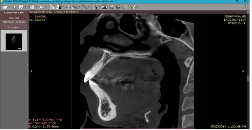
Figure 2.a Radiant software panel showing saggital view
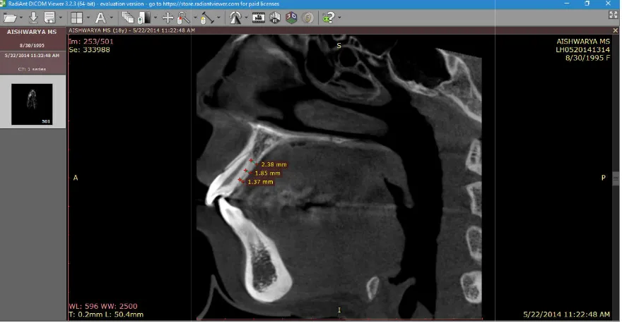
Figure 2.b Linear measurements of buccal cortical bone thickness
International Journal of Current Research, Vol. 9, Issue, 05, pp.50529-50535, May, 2017
[image:3.595.98.512.320.533.2]Fig1.Intraoral photographs after TAD placement and loading. a) right lateral view b) frontal view d) maxillary occlusal view e) mandibular occlusal view
Figure 2.a Radiant software panel showing saggital view
2.b Linear measurements of buccal cortical bone thickness
7
The Dicom files were then transferred to the radiant dicom viewer (64-bit) software for cortical bone thickness estimation. The length tool was used for linear measurements of bone thickness. (Figure: 2a,b,c). This method was used to measure the pre treatment and post treatment cortical bone thickness of all the maxillary anterior teeth and the mean value
RESULTS
Changes in palatal cortical bone
Comparison of mean values of maxillary palatal cortical bone width measured from CBCT scans before and after retraction of maxillary anterior teeth (Table 1&5).On comparison of the mean values of pre treatment and post treatment palatal cortical bone thickness, the mean values of post treatment is higher and are statistically significant at s1,s2 and s3 level (Table:2,3,4). At s1 level all four incisors showed a p value of <0.001. At s2 level right and left lateral incisor and right central incisor showed a p value of <0.001 while left central incisor cortical bone thickness changes showed p value of 0.002. At s3 level right and left lateral incisor and right central incisor showed a p value of <0.001 while left central incisor cortical bone thickness changes showed p value of 0.007.
Changes in buccal cortical bone
On comparison of the mean values of PRETREATMENT and POSTTREATMENT buccal cortical bone thickness of maxillary incisors the mean values of POSTTREATMENTl is
[image:4.595.80.520.63.292.2]50532 Dr. Nillan K Shetty et al. Comparison of Buccal and palatal cortical bone thickness changes during en
Figure 2.c Linear
Table 1. Comparison of mean values
CBCT scans before and after retraction of maxillary anterior teeth
Maxillary palatal right lateral
Maxillary palatal right central
Maxillary palatal left central
Maxillary palatal left lateral
ansferred to the radiant dicom thickness estimation. The length tool was used for linear measurements of bone 2a,b,c). This method was used to measure the pre treatment and post treatment cortical bone thickness of all the maxillary anterior teeth and the mean value was taken. .
Comparison of mean values of maxillary palatal cortical bone width measured from CBCT scans before and after retraction of maxillary anterior teeth (Table 1&5).On comparison of the re treatment and post treatment palatal the mean values of post treatment is higher and are statistically significant at s1,s2 and s3 level At s1 level all four incisors showed a p value of and left lateral incisor and right central incisor showed a p value of <0.001 while left central incisor cortical bone thickness changes showed p value of 0.002. At s3 level right and left lateral incisor and right central 01 while left central incisor cortical bone thickness changes showed p value of 0.007.
On comparison of the mean values of PRETREATMENT and POSTTREATMENT buccal cortical bone thickness of es of POSTTREATMENTl is
higher and is statistically not significant(Table 6).At s2 level right and left lateral incisor and right central incisor showed a p value of <0.001 while left central incisor cortical bone thickness changes showed p value of 0.012
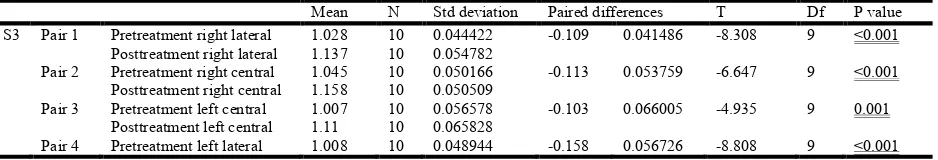
level right and left lateral incisor and right central incisor showed a p value of <0.001 while left central incisor cortical bone thickness changes showed p value of 0.001(Table 8)
DISCUSSION
The samples selected in the study was mainly bimaxillary dentoalveolar proclination and needed maximum anchorage control for retraction of the anterior teeth.
reinforced using temporary anchorage devices or micro implants in the alveolar bone b
molar in the right and left maxillary segments.
severely proclined or flared incisors, it is observed that the thickness of buccal cortical bone is comparitivly less due to anterior positioning of the incisors
extreme cases periodontal bone defects such as fenestration and dehiscence can be observed which cannot be visualised on routine diagnostic procedures such as clinical examination and conventional radiographs. It is of utmos
orthodontist to evaluate the quality and quantity of supporting bone prior to retraction of anterior teeth in to the space available, to avoid any iatrogenic damage such as loss of periodontal support, delayed closure of spaces and bon defects i.e fenestration and dehiscence.
[image:4.595.98.499.343.478.2]Comparison of Buccal and palatal cortical bone thickness changes during en-masse retraction using skeletal anchorage- A CBCT study
Figure 2.c Linear measurements of lingual cortical bone thickness
Comparison of mean values of maxillary palatal cortical bone width measured from CBCT scans before and after retraction of maxillary anterior teeth
T1 T2 Difference
X Sd X Sd X Sd
S1 1.33 0.06 1.12 0.10 0.03 0.09
S2 2.17 0.13 1.95 0.14 0.27 0.04
S3 2.72 0.10 2.40 0.21 0.36 0.20
S1 1.50 0.06 1.23 0.07 0.26 0.10
S2 2.54 0.33 2.16 0.37 0.37 0.23
S3 3.33 0.19 3.07 0.19 0.25 0.11
S1 1.51 0.07 0.87 0.11 0.26 0.059
S2 2.53 0.27 2.21 0.37 0.32 0.24
S3 3.32 0.19 1.81 0.77 0.25 0.23
S1 1.31 0.07 1.24 0.04 0.18 0.11
S2 2.22 0.11 1.95 0.14 0.27 0.04
S3 2.77 0.09 2.40 0.21 0.36 0.20
higher and is statistically not significant(Table 6).At s2 level right and left lateral incisor and right central incisor showed a p value of <0.001 while left central incisor cortical bone thickness changes showed p value of 0.012 (Table 7). At s3 level right and left lateral incisor and right central incisor showed a p value of <0.001 while left central incisor cortical bone thickness changes showed p value of 0.001(Table 8)
e samples selected in the study was mainly bimaxillary dentoalveolar proclination and needed maximum anchorage control for retraction of the anterior teeth. anchorage was reinforced using temporary anchorage devices or
micro-implants in the alveolar bone between 2nd premolar and first
molar in the right and left maxillary segments. In patients with severely proclined or flared incisors, it is observed that the thickness of buccal cortical bone is comparitivly less due to anterior positioning of the incisors against the cortical plate. In extreme cases periodontal bone defects such as fenestration and dehiscence can be observed which cannot be visualised on routine diagnostic procedures such as clinical examination and It is of utmost importance for the orthodontist to evaluate the quality and quantity of supporting bone prior to retraction of anterior teeth in to the space available, to avoid any iatrogenic damage such as loss of periodontal support, delayed closure of spaces and bone defects i.e fenestration and dehiscence.
masse retraction using
bone width measured from
P
0.001 0.001 0.001 0.001 0.001 0.001
0.059 0.001
50533 International Journal of Current Research, Vol. 9, Issue, 05, pp.50529-50535, May, 2017
Table 2. Comparison of the pre and post values at s1
Mean N Std. Deviation Paired differences T Df P value
S1 Pair 1 Pretreatment right lateral 1.333 10 0.06961 0.212 0.085088 7.879 9 <0.001
Post treatment right lateral 1.121 10 0.109793
Pair 2 Pretreatment right central 1.5 10 0.066667 0.266 0.104158 8.076 9 <0.001
Posttreatment right central 1.234 10 0.075454
Pair 3 Pretreatment left central 1.516 10 0.075307 0.268 0.059777 14.177 9 <0.001
Posttreatment left central 1.248 10 0.042374
Pair 4 Pretreatment left lateral 1.316 10 0.071678 0.18 4.758 9 0.001
[image:5.595.57.542.217.315.2]Posttreatment left lateral 1.136 10 0.104478
Table 3. Comparison of the pre and post values at s2
Mean N Std Deviation Paired differences T Df P value
S2 Pair 1 Pretreatment right lateral 2.172 10 0.1334 0.267 0.097758 8.637 9 <0.001
Posttreatment right lateral 1.905 10 0.197611
Pair 2 Pretreatment right central 2.54 10 0.336914 0.374 0.236653 4.998 9 0.001
Posttreatment right central 2.166 10 0.39733
Pair 3 Pretreatment left central 2.537 10 0.27244 0.321 0.244334 4.155 9 0.002
Posttreatment left central 2.216 10 0.378981
Pair 4 Pretreatment left lateral 2.228 10 0.119703 0.272 0.04341 19.814 9 <0.001
[image:5.595.51.542.355.451.2]Posttreatment left lateral 1.956 10 0.141044
Table 4. Comparison of the pre and post values at s3
Mean N Std deviation Paired differences T Df P value
S3 Pair 1 Pretreatment right lateral 2.726 10 0.10997 0.283 0.142521 6.279 9 <0.001
Posttreatment right lateral 2.443 10 0.219902
Pair 2 Pretreatment right central 3.332 10 0.197135 0.258 0.117265 6.957 9 <0.001
Posttreatment right central 3.074 10 0.192827
Pair 3 Pretreatment left central 3.326 10 0.199566 0.253 0.231903 3.45 9 0.007
Posttreatment left central 3.073 10 0.166002
Pair 4 Pretreatment left lateral 2.772 10 0.098522 0.369 0.204094 5.717 9 <0.001
Posttreatment left lateral 2.403 10 0.218177
Table 5. Comparison of mean values of maxillary buccal cortical bone width measured from CBCT scans before and after retraction of maxillary anterior teeth
T1 T2 Difference P
X Sd X Sd X Sd
Maxillary labial right lateral S1 0.81 0.06 0.84 0.12 -0.03 0.13 0.001
S2 0.92 0.03 1.01 0.04 -0.08 -0.10 0.001
S3 1.02 0.04 1.13 0.05 -0.10 0.04 0.001
Maxillary labial right central S1 0.84 0.04 0.87 0.08 -0.03 0.11 0.001
S2 0.89 0.04 1.00 0.06 -0.10 0.05 0.001
S3 1.04 0.05 1.15 0.05 -0.11 0.05 0.001
Maxillary labial left central S1 0.83 0.08 0.87 0.11 -0.03 0.09 0.001
S2 0.90 0.03 0.97 0.08 -0.06 0.06 0.001
S3 1.00 0.05 1.11 0.06 -0.10 0.06 0.001
Maxillary labial left lateral S1 0.82 0.06 0.87 0.10 -0.04 0.10 0.001
S2 0.84 0.05 1.00 0.07 0.27 0.04 0.001
S3 1.00 0.04 1.16 0.05 -0.15 0.05 0.001
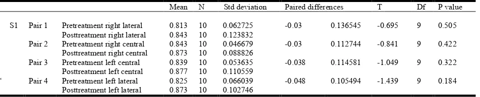
Table 6. Comparison of the pre and post maxillary buccal cortical bone thickness values at s1
Mean N Std deviation Paired differences T Df P value
S1 Pair 1 Pretreatment right lateral 0.813 10 0.062725 -0.03 0.136545 -0.695 9 0.505
Posttreatment right lateral 0.843 10 0.123832
Pair 2 Pretreatment right central 0.843 10 0.046679 -0.03 0.112744 -0.841 9 0.422
Posttreatment right central 0.873 10 0.088826
Pair 3 Pretreatment left central 0.839 10 0.053635 -0.038 0.114581 -1.049 9 0.322
Posttreatment left central 0.877 10 0.110559
‘ Pair 4 Pretreatment left lateral 0.825 10 0.066039 -0.048 0.105494 -1.439 9 0.184
[image:5.595.103.493.501.635.2] [image:5.595.63.539.674.771.2]CBCT is used in our study for precise qualitative and quantitave evaluation of the supporting alveolar bone. The amount of retraction that can be carried out for the anteriors is limited to the cortical plates on the labial and palatal sides also known as the orthodontic walls. As all the samples taken, underwent first premolar extraction, maximum amount of space available was used for retaction of anteriors using micro-implants which prevents taxing of anchorage from the posterior segment. Orthodontic force is known to remodel the supporting alveolar bone resulting in movement of the teeth along the socket. Previous studies have shown that the displacement of teeth and supporting alveolar bone is not at the
same rate13. Remodelling along the alveolar bone itself is also
differential i.e the amount of remodelling at different levels of alveolar bone and anatomic locations, is also varied. The results of the present study stated that there was a resultant increase in labial cortical bone thickness whereas the cortical bone thickness of the palatal region decreased to a significant level.this finding is supported by the similar pattern of bone
remodelling in study conducted by Wehrbein et al,who
concluded that there was significant reduction in the cortical bone thickness toward the direction of tooth movement.
The increase in the labial cortical plate thickness was also observed to be differential at levels, s1, s2 and s3. Although there was minimal increase in the post treatment thickness of labial cortical plate at level s1, the difference was not statistically significant. This differential remodelling can be explained by the bone bending theory proposed by Farrar which explains the displacement by bending of the bone rather than absolute remodelling. The retraction force was applied from the micro-implant as close to centre of resistance as possible to facilitate bodily tooth movement of the anterior segment. during the levelling and aligning phase. Complete torque expression was achieved by rectangular arch wire, to position the root in the cancellous bone, which was positioned close to the labial cortical plate. The post treatment CBCT was taken immediately after completion of treatment to evaluate the immediate effects of retraction force on the cortical plate thickness, and eliminate any change due to osteoblastic activity during the retentive phase. New alveolar bone formation at the defect sites are expected to form by 4 to 6 months of retention period. Ten Hoeve and Mulier, on the basis of their laminagraphic evidence, suggested that the cortical plate would be reestablished within 6 months, irrespective of the amount the tooth movement.
This effect can be attributed to two reasons, first being the osteoblastic activity during the retention phase and second being the relapse of tooth movement and torque. The cortical plate was evaluated around the four anterior teeth i.e centrals and lateral incisors of left and right side. The change in thickness was not uniform along the entire segment. Along the labial cortical plate of left central incisor ,the mean increase at level s1,s2,s3 was 0.068mm and 0.015mm respectively. Where as for left lateral, it was 0.0157mm and 0.0158mm at s1,s2 and s3 respectively. The values varied between the right and left segments , at right central the increase in thickness was at s1,0.108mm at s2 and 0.113mm at s3 .and for right lateral the amount of increase was at s1,0.089 at s2 and 0.109mm at s3. The changes at s1 are minimal and statistically insignificant. Lingual cortical plate being along the direction of force applied ,undergoes osteoclastic activity resulting in apparent reduction in cortical plate thickness after retraction. The decrease in cortical plate thickness of left cental incisor at level s1,s2,s3 was 0.268,0.321 and 0.253 respectively. Where as for left lateral,it was 0.18,0.272 and 0.369 at s1,s2 and s3 respectively. At right central the decrease in thickness was 0.266 at s1, 0.374 at s2 and0.258 at s3 .and for right lateral the amount of increase was 0.212 at s1 0.267 at s2 and 0.283 at s3.Melsen stated that there is more osteoblastic activity in tension sites and osteoclastic activity on the compression, which explains the increased thickness at labial cortical plate and reduced thickness at palatal cortical plate.
Conclusion
The results indicates that when maxillary anteriors are retracted using TADs there is differential deposition and resorption in the anterior cortical bone thickness. These changes can be precisely measured using CBCT and will help to reduce the risk of dehiscence and fenestration. Long term follow up is needed to evaluate the amount of cortical bone repair that takes place during the retentive period.
REFERENCES
Al-Sibaie, S., Hajeer, M.Y. 2013. Assessment of changes
following en-masse retraction with mini-implants
anchorage compared to two-step retraction with
[image:6.595.49.528.65.153.2]conventional anchorage in patients with class II division 1 malocclusion: a randomized controlled trial. Eur J
Table 7. Comparison of the pre and post maxillary buccal cortical bone thickness values at s2
Mean N Std deviation Paired differences T Df P value
S2 Pair 1 Pretreatment right lateral 0.922 10 0.036758 -0.089 0.039285 -7.164 9 <0.001
Posttreatment right lateral 1.011 10 0.041218
Pair 2 Pretreatment right central 0.895 10 0.041164 -0.108 0.053707 -6.359 9 <0.001
Posttreatment right central 1.003 10 0.066173
Pair 3 Pretreatment left central 0.907 10 0.032335 -0.068 0.068767 -3.127 9 0.012
Posttreatment left central 0.975 10 0.082496
Pair 4 Pretreatment left lateral 0.849 10 0.059339 -0.157 0.082064 -6.05 9 <0.001
Posttreatment left lateral 1.006 10 0.070585
Table 8. Comparison of the pre and post maxillary buccal cortical bone thickness values at s3
Mean N Std deviation Paired differences T Df P value
S3 Pair 1 Pretreatment right lateral 1.028 10 0.044422 -0.109 0.041486 -8.308 9 <0.001
Posttreatment right lateral 1.137 10 0.054782
Pair 2 Pretreatment right central 1.045 10 0.050166 -0.113 0.053759 -6.647 9 <0.001
Posttreatment right central 1.158 10 0.050509
Pair 3 Pretreatment left central 1.007 10 0.056578 -0.103 0.066005 -4.935 9 0.001
Posttreatment left central 1.11 10 0.065828
Pair 4 Pretreatment left lateral 1.008 10 0.048944 -0.158 0.056726 -8.808 9 <0.001
[image:6.595.69.538.182.262.2]Orthod. 2014 Jun;36(3):275-83. doi: 10.1093/ejo/cjt046. Epub Jun 20
Bae, S.M., Park, H.S., Kyung, H.M., Kwon, O.H., Sung, J.H.
2002. Clinical application of micro-implant anchorage. J
Clin Orthod., 36: 298-302.
Creekmore, T.D. 1983. The possibility of skeletal anchorage. J
Clin Orthod., 17:266–269
Deguchi, T., Takano-Yamamoto, T., Kanomi, R., Hartsfield, J.K. Jr, Roberts, W.E., Garetto, L.P. 2003. The use of small
titanium screws for orthodontic anchorage. J Dent Res.,
82:377–381
Engelking, G., Zachrisson, B.U. 1982. Effect of incisor repositioning on the monkey periodontium after expansion
through the cortical plate. Am J Orthod., 82:23-32.
Ferreira, P.P., Torres, M., Campos, P.S., Vogel, C.J., de Araújo, T.M., Rebello, I.M. 2013. Evaluation of buccal bone coverage in the anterior region by cone-beam
computed tomography. Am J Orthod Dentofacial
Orthop. Nov;144(5):698-704
Grauer, D., Cevidanes, L.S., Proffit, W.R. 2009. Working with
DICOM craniofacial images. Am J Orthod Dentofacial
Orthop., 136:460–470.
Hatcher, D.C., Dial, C., Mayorga, C. 2003. Cone beam CT for presurgical assessment of implant sites. J Calif Dent Assoc. 31:825–833.
Hyo-Sang Park and Tae-Geon Kwon ,Sliding Mechanics with
Microscrew Implant Anchorage.Angle Orthod
2004;74:703–710.
Kajiyama, K., Murakami, T., Shigeru, Y. 1993.Gingival reactions after experimentally induced extrusion of the
upper incisors in monkeys. Am J Orthod Dentofacial
Orthop; 104:36-47.
Kaur, H., Pavithra, U.S., Abraham, R. 2013. Prevalence of malocclusion among adolescents in South Indian
population..J Int Soc Prev Community Dent.
Jul;3(2):97-102. doi: 10.4103/2231-0762.122453.
Mah, J., Bergstrand, F. 2005. Temporary anchorage devices: a
status report. J Clin Orthod., 39:131–136
Mclaughlin, R.P., Bennett, J.C. 1991. Anchorage control during leveling and aligning with a preadjusted appliance
system. J Clin Orthod., 25:687–696
Melsen B, Costa A. Immediate loading of implants used for orthodontic anchorage. Clin Orthod Res. 2003:23–28 Melsen, B., Agerbek, N., Eriksen, J., Terp, S. 1988. New
attachment through periodontal treatment and orthodontic
intrusion. Am J Orthod Dentofacial Orthop, 94:104-16.
Melsen, B., Agerbek, N., Markenstam, G. 1989. Intrusion of
incisors in adult patients with marginal bone loss. Am J
Orthod Dentofacial Orthop, 96:232-41.
Misch, K.A., Yi, E.S., Sarment, D.P. 2006. Accuracy of cone beam computed tomography for periodontal defect measurements.J Periodontol.77:1261–1266.
Murakami, T., Yokota, S., Takahama, Y. 1989. Periodontal changes after experimentally induced intrusion of the upper
incisors in Macaca fuscata monkeys. Am J Orthod
Dentofacial Orthop., 95:115-26.
Murray, C. Meikle, The dento-maxillary complex and overjet correction in Class II, Division I malocclusion: Objectives
of skeletal and alveolar remodeling, Am J Orthod,
February,1980
Park, H.S., Bae, S.M., Kyung, H.M. Micro-implant anchorage for treatment of skeletal Class I bialveolar protrusion. J Clin Orthod 001;35:417-22.
Reitan, K. 1963. Influence of variation in bone type and
character on tooth movement. Eur Orthod Soc Tr.,
39:137-54.
Reitan, K. 1964. Effects of force magnitude and direction of
tooth movement on different alveolar bone types. Angle
Orthod, 34:244-55.
Sarabjeet Singh Sandhu, Nidhi bansal ,Incidence of Malocclusions in India - A Review :, Navreet Sandhu J Oral Health Comm Dent 2012;6(1)21-24
Sarikaya, S., Haydar, B., Ciger, S., Ariyürek, M. 2002. Changes in alveolar bone thickness due to retraction of
anterior teeth. Am J Orthod Dentofacial Orthop.
Jul;122(1):15-26.
Sung-Seo Mo; Seong-Hun Kim; Yoon-Ah Kook; Do-Min Jeong; Kyu-Rhim Chung;Gerald Nelson, Resistance to Immediate Orthodontic Loading of Surface-Treated Mini-Implants Angle Orthod 2010;80:123–129
Upadhyay, M., Yadav, S., Nagaraj, K., Patil, S. 2008. Treatment effects of mini-implants for en-masse retraction of anterior teeth in bialveolar dental protrusion patients: a
randomized controlled trial. Am J Orthod Dentofacial
Orthop., 134:18–29.e1
Upadhyay, M., Yadav, S., Patil, S. 2008. Mini-implant anchorage for en-masse retraction of maxillary anterior
teeth: a clinical cephalometric study. Am J Orthod
Dentofacial Orthop. 134:803–810.
Vardimon, A.D., Graber, T.M., Voss, L.R., Lemke, J. 1991. Determinants controlling iatrogenic external root resorption and repair during and after palatal expansion. Angle Orthod 61:113-24.
Vincent De Angelis, Observations on the response of alveolar bone to orthodontic force, Amer. J. Orthodont. September 1970
Wainwright, W.M. Faciolingual tooth movement: its influence on the root and cortical plate. Am J Orthod 1973;64:278-302.