warwick.ac.uk/lib-publications
Original citation:
Lan, Rong and Tao, Shanwen. (2016) A simple high-performance matrix-free biomass molten
carbonate fuel cell without CO2 recirculation. Science Advances, 2 (8). e1600772.
Permanent WRAP URL:
http://wrap.warwick.ac.uk/81326
Copyright and reuse:
The Warwick Research Archive Portal (WRAP) makes this work of researchers of the
University of Warwick available open access under the following conditions.
This article is made available under the Creative Commons Attribution 4.0 International
license (CC BY 4.0) and may be reused according to the conditions of the license. For more
details see:
http://creativecommons.org/licenses/by/4.0/
A note on versions:
The version presented in WRAP is the published version, or, version of record, and may be
cited as it appears here.
A P P L I E D S C I E N C E S A N D E N G I N E E R I N G 2016 © The Authors, some rights reserved; exclusive licensee American Association for the Advancement of Science. Distributed under a Creative Commons Attribution License 4.0 (CC BY). 10.1126/sciadv.1600772
A simple high-performance matrix-free
biomass molten carbonate fuel cell without
CO
2
recirculation
Rong Lan1and Shanwen Tao1,2*
In previous reports, flowing CO2 at the cathode is essential for either conventional molten carbonate fuel cells
(MCFCs) based on molten carbonate/LiAlO2electrolytes or matrix-free MCFCs. For the first time, we demonstrate
a high-performance matrix-free MCFC without CO2recirculation. At 800°C, power densities of 430 and 410 mW/cm2
are achieved when biomass—bamboo charcoal and wood, respectively–is used as fuel. At 600°C, a stable performance is observed during the measured 90 hours after the initial degradation. In this MCFC, CO2is produced
at the anode when carbon-containing fuels are used. The produced CO2then dissolves and diffuses to the cathode
to react with oxygen in open air, forming the required CO23or CO 2
4 ions for continuous operation. The dissolved O2 ions may also take part in the cell reactions. This provides a simple new fuel cell technology to directly convert carbon-containing fuels such as carbon and biomass into electricity with high efficiency.
INTRODUCTION
In terms of energy sources, about 87% of the energy consumed in the
world depends on fossil fuels (1), which are a major source of CO2
emission. It is desirable to integrate more renewable energy sources with lower carbon footprints. Biomass from energy crops, agricultural residues, wastes and residues, and forestry is an important renewable energy source. It is estimated that global biomass potential is about
200 EJ (up to 600 EJ), which is about one-third of the world’s total
en-ergy consumption (2). Biomass energy is used to generate heat through
combustion or to generate electricity by supplying steam for the same kind of steam-electric generators used to burn fossil fuels. Fuel cell technology is another type of technology that is used to convert the chemical energy in biomass into electricity. Biomass can be used to produce charcoal through pyrolysis. The charcoal produced is an ideal
fuel for direct carbon fuel cells (DCFCs) (3–5). Alternatively, biomass,
such as starch, cellulose, and sugar, can be used as fuel for electricity generation through microbial fuel cells, but the power density is quite
small (Table 1) (6–8). It has been determined that intermediate- to
high-temperature fuel cells, such as molten alkaline fuel cells, molten carbonate fuel cells (MCFCs), solid oxide fuel cells (SOFCs), and hybrid MCFC/SOFC, use carbon or charcoal derived from biomass
for power generation with reasonably high power density (3–5,9–14).
Liquid tin anode SOFCs were also investigated for DCFCs (15), but
the deposition of nonconductive SnO2at the anode triple-phase
bound-ary is a potential problem (3). The high requirements of materials in
contact with the liquid anode are also potential challenges. Lignin was also reported as fuel for a hybrid MCFC/SOFC fuel cell with
a power density of 25 mW/cm2at 560°C (16). An unprecedented high
power density of 878 mW/cm2 has been achieved at 750°C when a
hybrid MCFC/SOFC was used for DCFCs using a special charcoal
(a pyrolyzed medium-density fiberboard) as the fuel (5). However,
conventional SOFC technology does not yet meet the reliability and durability targets for large-scale commercialization. Although
mate-rials improvement plays a central role in the development process, sys-tem and stack design must integrate degradation analysis to achieve the
lowest cost of electricity (17). The introduction of molten carbonate in
the hybrid MCFC/SOFC DCFCs will make the hybrid MCFC/SOFC technology more challenging, particularly on materials in contact with the molten carbonate. Therefore, it is necessary to develop DCFCs or direct biomass fuel cells based on a simple design to avoid the chal-lenges associated with the complicated cell design.
MCFC is an important type of fuel cell for efficient power
gen-eration (18,19). Although significant progress has been made in the
last 40 years, MCFC technology still faces challenges, such as low
power density, the stability of LiAlO2matrix in the carbonate/LiAlO2
electrolyte (20), and the corrosion of electrode and bipolar materials
(21,22). There is also a requirement to recirculate CO2from the anode
exhaust to the cathode to react with O2in air to generate CO23ions
as the charge carriers according to reaction 1 and to maintain the carbonate composition. This also complicates the balance-of-plant
equipment (18)
CO2þ1=2O2þ2e→CO23 ð1Þ
Recirculation of CO2 in MCFC not only complicates the system
but also has a significant negative effect on overall efficiency (23).
The use of a matrix also increases the internal resistance, leading to reduced power density. Therefore, matrix-free MCFCs give a higher power density.
MCFCs are attractive for DCFCs/direct biomass fuel cells because of their excellent wetting property to the solid fuels, which achieve a
high power density, and their high tolerance to impurities (3). Ahnet al.
(11) reported a direct carbon MCFC (DCMCFC), where carbon fuel
[5 weight percent (wt %)] was premixed with a molten carbonate
elec-trolyte, with air and CO2bubbled through a porous cathode tube. In
another report, a porous anode tube was used for a DCMCFC (24). In
both cells, flowing CO2at the cathode is essential (11,24). Air
bub-bling through the cathode is in direct contact with the fuel and, thus, 1School of Engineering, University of Warwick, Coventry CV4 7AL, UK.2Department of
Chemical Engineering, Monash University, Clayton, Melbourne, Victoria 3800, Australia. *Corresponding author. Email: [email protected]
on August 31, 2016
http://advances.sciencemag.org/
chemically reacts with the carbon fuel, forming CO or CO2. This direct
reaction will generate heat rather than electricity, leading to
de-creased electrical efficiency (3). In a recent report where a porous
nickel rod was used as the anode, mixed graphite and (Li,K)2CO3
was used as slurry fuel, and mixed CO2 and O2was flowed at the
cathode (25), good performance was achieved.
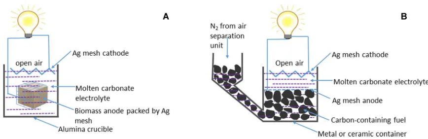
Here, we report a simple design for MCFCs that does not involve
flowing CO2at the cathode (Fig. 1A). In this design, solid fuel is put
in a cage made of conducting materials such as silver mesh,
elimi-nating the need to flow CO2at the cathode. This will greatly simplify
the cell manufacturing process and reduce the operating cost.
Contin-uous fuel cell operation can be achieved through a cell design shown in Fig. 1B. Solid fuels such as carbon or biomass are ideal for this new type of MCFC.
In our new design, unlike previously reported MCFCs (11,24),
air or oxygen was not bubbling into the molten carbonate electrolyte. The only possible direct chemical reaction between the fuel and
ox-ygen is through dissolved molecular oxox-ygen (O2). It has been reported
that, at a temperature of 600°C, the dissolved oxygen in 62 mole
per-cent (mol %) Li2CO3–38 mol % K2CO3and that in 52 mol % Li2CO3–
48 mol % Na2CO3are in charged forms, such as superoxide (O2) or
peroxymonocarbonate (CO2
[image:3.594.44.560.88.562.2]4 ), and the dissolved molecular oxygen
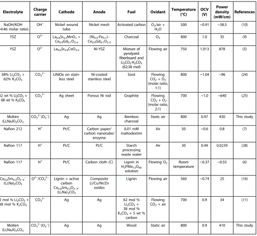
Table 1. Comparison of reported typical fuel cell performances on using carbon and biomass as the fuel.YSZ, yttria-stabilized zirconia.
Electrolyte Charge
carrier Cathode Anode Fuel Oxidant
Temperature (°C)
OCV (V)
Power density (mW/cm)
References
NaOH/KOH (54:46 molar ratio)
OH− Nickel wound tube
Nickel mesh Activated carbon O2/air +
H2O
500 ~0.91 ~38.5 (10)
YSZ O2− La0.8Sr0.2MnO3+
Ce0.9Gd0.1O2-d
(Ni0.9-Fe0.1
)-Ce0.9Gd0.1O2-d
Charcoal O2 800 1.0 35 (9)
YSZ O2− La
0.6Sr0.4CoO3-d Ni-YSZ Mixture of
pyrolyzed fiberboard and
Li2CO3-K2CO3
(62:38 mol)
Flowing air 750 1.013 878 (5)
38% Li2CO3+
62% K2CO3
CO32− LiNiOx on
stain-less steel
Ni-coated stainless steel
Soot Flowing
CO2+ O2
(molar ratio, 1:1)
800 ~1.04 ~96 (24)
32 wt % Li2CO3+
68 wt % K2CO3
CO32− Ag sheet Porous Ni rod Graphite Flowing
CO2+ O2
(molar ratio, 2:1)
700 ~1.0 ~640 (25)
Molten (Li,Na,K)2CO3
CO32−(O2−) Ag Ag Bamboo
charcoal
Static air 800 0.97 430 This study
Nafion 212 H+ Pt/C Carbon paper/
carbon nanotube/ enzyme
0.01 mM maltodextrin
Air 50 ~0.6 0.8 (7)
Nafion 117 H+ Pt/C Pt/C Starch
processing waste water
Air 30 0.49 0.0239 (38)
Nafion 117 H+ Pt/C Carbon cloth (C) Lignin in
H3PMo12O40
solution
Flowing O2 Room
temperature
~0.37 ~0.55 (6)
Ce0.8Sm0.2O2−d−
(Li,Na)2CO3
O2−/CO3
2− Lignin + active
carbon Ce0.8Sm0.2O2−d
-(Li,Na)2CO3
Composite Li/Cu/Ni/Zn oxides
Lignin Flowing air 560 ~0.74 25 (16)
62 mol % Li2CO3+
38 mol % K2CO3
CO32− Ag Ag 62 mol %
Li2CO3+
38 mol % K2CO3+ 5 wt %
carbon
Flowing CO2+ air
700 0.9 34 (11)
Molten (Li,Na,K)2CO3
CO32−(O2−) Ag Ag Wood Static air 800 0.9 410 This study
on August 31, 2016
http://advances.sciencemag.org/
(O2) at high temperatures is negligible (26). In the reaction between
charged oxygen species and the anode, there must be a loss of electrons to generate electricity. Under this circumstance, the charged dissolved oxygen is used as the charge carrier. The possible cathode reactions are
O2þe→O2 ð2Þ
CO2þO2þ2e→CO24 ð3Þ
The formed anions will diffuse in the molten carbonate and react with the solid fuel at the anode. If carbon is used as the fuel, the re-actions at the anode are
CþO2 →CO2þe ð4Þ
CþCO24→2CO2þ2e ð5Þ
Cþ2CO23→3CO2þ4e ð6Þ
For reactions 2 and 4, the charge carriers are O2 ions; thus, CO2is
not required for the reaction. Therefore, theoretically, an MCFC can
work without flowing CO2.
In our new cell design, at high working temperatures, the efficien-cy loss due to the direct reaction between molecular oxygen and fuel will be minimized because of the low solubility of molecular
O2in molten carbonates (26). Moreover, the possible stability issues
associated with decomposition of carbonates can also be avoided
be-cause of the in situ formation of CO2at the anode, which suppresses
carbonate decomposition. CO2 solubility in molten carbonates is
much higher than that of O2(24,26,27). The solubility of CO2in
the molten ternary eutectic mixture Li2CO3-Na2CO3-K2CO3(43.5/
31.5/25.0 mol %) at 700°C was 9.5 × 10⁻²mol/liter (27). Thus, the
produced CO2at the MCFC anode can dissolve and diffuse to the
cathode through the molten carbonates to react with O2in air,
form-ing CO24and CO23ions according to reactions 1 and 3. The formed
CO2
4 and CO23ions then diffuse to the anode to react with the fuel
according to reactions 5 and 6. Under this circumstance, flowing CO2
at the cathode is not required in the matrix-free MCFCs. If the CO2
generated at the anode is beyond the solubility limit in molten
car-bonates, the“extra”CO2may also pass through the electrolyte to the
cathode and then react with O2in air, forming carbonate ions to take
part in the fuel cell reaction.
RESULTS
Direct charcoal MCFC
On the basis of the analysis above, two fuel cells were tested using the newly designed cell shown in Fig. 1A, one with the anode made of bamboo-derived charcoal and the other made of wood. Biomass was used as fuel in the fuel cell because it is nearly carbon-neutral.
The mixture of Li2CO3, Na2CO3, and K2CO3was used as the
elec-trolyte, and the silver mesh cathode was exposed to static air without
CO2flow. Experimental details can be found in the Supplementary
Materials.
The fuel cell performance of the direct charcoal fuel cell is shown in Fig. 2A. At 600°C, the open-circuit voltage (OCV) of the cell was
0.69 V. Maximum current and power densities of ~500 mA/cm2and
88 mW/cm2, respectively, were observed. A key feature on theI-V
curve (Fig. 2A) is the oscillation of the curve at high current
densi-ties. This is due to the formation of gas (CO and/or CO2) on the
char-coal surface, which may temporarily separate the contact between the silver anode and the charcoal, leading to a lower current. However, once the gas bubble is released or dissolved in the molten carbonates, the anode/charcoal contact is recovered and a large current density is
observed. The formed CO may be oxidized in situ to CO2by the anions,
such as O2, CO2
3 , and CO24. When the operating temperature increased
to 650°C, the OCV jumped to 0.9 V. This is fairly close to the
the-oretical OCV of DCFCs (1.0 V) (3). At 750°C, the OCV was 0.98 V,
and then it decreased to 0.85 V when the operating temperature further increased to 800°C. The OCV drop may be related to the formation of intermediate CO at the anode. At high temperatures, CO might be formed via the reverse Boudouard reaction
CþCO2→2CO ð7Þ
This reaction is spontaneous at a temperature above 700°C (28).
[image:4.594.78.512.70.211.2]The presence of alkali carbonates, such as Na2CO3and K2CO3, will
Fig. 1. Schematic diagram of a matrix-free MCFC without flowing CO2at the cathode.(A) Caged anode. (B) Design for continuous operation.
on August 31, 2016
http://advances.sciencemag.org/
suppress the formation of CO; therefore, decreased OCV was shifted
to 800°C in our study (29). The generated CO can be electrochemically
oxidized in situ to CO2according to the reaction
COþCO23→ 2CO2þ2e ð8Þ
whereas the OCV for oxidation of CO to CO2decreased at elevated
temperatures (3,30,31). Decreased OCV at high temperatures was
also observed for DCFC based on ceria-gadolinia electrolyte (31).
When alkali carbonate was used as electrolyte, interactions involving the alkali metal in the melt may have contributed to the observed cell
potential, which is complicated (3,28). At 800°C, the maximum
cur-rent and power densities were 2.2 A/cm2(Fig. 2A) and 430 mW/cm2
(Fig. 2B). This power density is slightly lower than that of the highest
DCFC based on the hybrid MCFC/SOFC electrolyte (5) and MCFC
when mixed CO2and O2was flowing at the cathode (25), but is higher
than the power density of DCFCs reported by other groups (Table 1). However, the cell design in this study is much simpler than the reported
hybrid MCFC/SOFC (5) cell and the MCFC (25), thus making it easier
to fabricate and maintain. Moreover, this is just a starting point, and it is expected that more efficient electrode materials can be identified to further improve the power density. The impedance spectra mea-sured at the OCV of the direct charcoal fuel cell are shown in Fig. 2C.
At 800°C, the overall resistance was 0.53 ohm·cm2. From the slope of
theI-Vcurve, it was found that the resistance of the cell decreased at a
lower voltage and at a higher current density (Fig. 2A). At a high
cur-rent density, a large amount of CO2is produced. The produced CO2
will increase the local CO2concentration in the melts and cathode and,
thus, increase the CO23ion concentration, resulting in a higher current
density. However, in other DCFCs, a current drop at low operating
volt-age was observed because of the short supply of fuel (5,11). This was
not observed in this study because of the good contact between the silver anode and the charcoal fuel. The current oscillation at 800°C was not significant, possibly because of the increased solubility of
CO2at higher temperatures. The OCVs of the direct charcoal MCFC
at different temperatures are shown in fig. S1. The highest OCV of 0.98 V was observed at 750°C. This is slightly lower than the theore-tical OCV of DCFCs (~1.0 V). In a DCFC, partial oxidation of carbon
to CO can lead to a higher OCV (>1.0 V) (3,5,28).
Cþ1=2O2→CO ð9Þ
The fact that the OCV of the cell is slightly lower than 1.0 V
in-directly indicates that the complete oxidation of carbon to CO2is the
dominant reaction, implying high electricity efficiency (3).
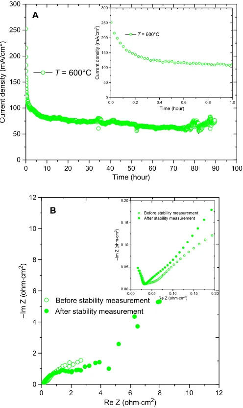
The performance stability of the DCMCFC at 600°C is shown in Fig. 3A. The operating voltage was 0.5 V. Some initial decrease in current density was observed in the first 20 min, and then the cell tended to give a stable performance. This decrease could be related to the loss of contact between the charcoal and the silver mesh due to the consumption of carbon on the surface during the fuel cell mea-surement. This may lead to increased electrode polarization re-sistance that is confirmed by ac impedance spectra for the cell before and after the stability measurements (Fig. 3B). It is expected that better contact with the anode can be achieved for the design shown in Fig. 1B.
0 500 1000 1500 2000 2500
0.0 0.2 0.4 0.6 0.8 1.0
600°C 650°C 700°C 750°C 800°C
Voltage (V)
Current density (mA/cm2)
0 500 1000 1500 2000 2500
Current density (mA/cm2) A
0 100 200 300 400 500
Power density (mW/cm
2)
600°C 650°C 700°C 750°C 800°C
B
0.0 0.5 1.0 1.5 2.0 2.5 3.0
0.0 0.5 1.0 1.5 2.0 2.5 3.0
600°C 650°C 700°C 750°C 800°C C
0.00 0.05 0.10 0.15 0.20 0.00
0.05 0.10 0.15 0.20
600°C 650°C 700°C 750°C 800°C
Re Z (ohm cm2)
Re Z (ohm cm2)
–Im Z (
ohm cm
2)
–Im Z (
ohm cm
[image:5.594.57.270.133.677.2]2)
Fig. 2. (AtoC)I-Vcurves (A),I-Pcurves (B), and ac impedance spectra (C) of DCMCFC.
on August 31, 2016
http://advances.sciencemag.org/
Scanning electron microscopy (SEM) observations were carried out on the remaining charcoal after fuel cell measurements as well as before the measurements (fig. S1, A and B). It can be seen that the charcoal is quite porous with close pores. This type of microstructure is not ideal as compared to microstructures with open pores, which allow the diffusion of carbonate melt into the pore, thus extending the anode reaction zone and decreasing the anode polarization resistance,
leading to high power density (32). It is believed that the power
den-sity of DCFCs based on molten carbonate electrolytes can be further improved if carbon with open pores is used as the fuel. Microstructure change of the remaining charcoal during the measurement was in-significant, as shown in fig. S1B. Energy dispersive spectroscopy (EDS) of the charcoal before and after fuel cell measurements is shown in fig. S2. It can be seen that the major composition of the charcoal is
car-bon, which is expected. After the fuel cell measurement and removal of the electrolyte by water, besides carbon, a tiny amount of magne-sium (about 1 wt %) appears in the EDS pattern. The possible source of the magnesium is the internal part of the charcoal, which was ex-posed to the surface after the surface charcoal was consumed during the fuel cell operation. Another possible source is the carbonate
elec-trolyte; MgCO3is insoluble in water, and thus sticks to the charcoal
surface. The signal for oxygen is from the air in the SEM chamber, although there could be oxygen in wood.
Direct wood MCFC
Because charcoal is normally produced through pyrolysis of biomass such as wood, bamboo, starch, and sawdust, during this pyrolysis, tar, bio-oil, and biogas are formed along with the charcoal. These are also
potential fuels for MCFCs for power generation (33). The combustion
of this produced biogas in the air can provide heat to maintain the high operating temperature. Therefore, directly using biomass such as wood as the fuel in an MCFC can maximize energy utilization. Therefore, wood, which is a typical biomass, was directly used as fuel for the newly designed MCFC (Fig. 1A).
When wood was used as the fuel, it was partially pyrolyzed dur-ing the heatdur-ing-up process for the cell. At 600°C, an OCV of 0.96 V was
observed. The maximum current and power densities were 150 mA/cm2
and 52 mW/cm2, respectively. Oscillation of theI-Vcurve was
ob-served at all measured temperatures. This is probably related to the in situ pyrolysis of the wood that may produce biogas bubbles, thus temporarily separating the contact of the fuel and silver anode. Higher fuel cell performance was observed at elevated tempera-tures. At 800°C, the observed OCV was 0.90 V. The OCV of wood MCFC is fairly close to that of direct charcoal MCFC (fig. S3). EDS analysis indicates that a small amount of Si [likely in the form of
SiO2 or M2SiO3(M = Li, Na, or K) as described below] in wood
might slightly affect the catalytic activity of the anode; thus, the OCV
needs further investigation, although SiO2 may be converted into
M2SiO3(M = Li, Na, or K). Maximum current and power densities
of 1.98 A/cm2(Fig. 4A) and 410 mW/cm2(Fig. 4B), respectively, were
achieved at 800°C. This power density is just slightly lower than that
of direct charcoal MCFC at the same temperature (430 mW/cm2).
The application of direct biomass MCFCs will save additional costs
on a pyrolysis reactor, and the in situ formed by-products—tar,
bio-oil, and biogas—are directly converted into electricity or combustion
to heat up the fuel cell. This is a better choice for biomass-to-electricity conversion. At 800°C, the overall resistance of the wood MCFC was
0.56 ohm·cm2(Fig. 4C). Again, the measured resistance at OCV could
be slightly higher because the initial activation of carbon or biomass
could be difficult, particularly at lower temperatures (11). Figure S2
(C and D) shows the SEM pictures of the wood before and after fuel cell measurement. The wood is dense before fuel cell measurement, whereas a porous cracked charcoal was obtained after the fuel cell measurement, indicating the occurrence of in situ pyrolysis. EDS analysis indicates that the wood is composed of C, N, and O with a tiny amount of Si, whereas H cannot be picked up by EDS because it is too light (fig. S2). After the fuel cell measurement, the wood was converted into charcoal, and carbon and a small amount of Si (~0.2 wt %) were observed. It is believed that, after fuel cell
mea-surement, Si is likely presented in the form of SiO2or further reacts
with molten carbonate electrolyte to form M2SiO3(M = Li, Na, or K).
The SiO2in biomass is a typical poisoner for the anode for SOFCs
0 10 20 30 40 50 60 70 80 90 100
0 50 100 150 200 250 300
Current density (mA/cm
2)
Time (hour)
T = 600°C
A
0 2 4 6 8 10 12
0 2 4 6 8 10 12
Before stability measurement After stability measurement B
0.0 0.2 0.4 0.6 0.8 1.0
0 50 100 150 200 250 300 Cur rent dens ity (mA/cm 2) Time (hour)
T = 600°C
0.00 0.05 0.10 0.15 0.20 0.00
0.05 0.10 0.15 0.20
Before stability measurement After stability measurement
–Im Z (
ohm cm
2)
Re Z (ohm cm2)
Re Z (ohm cm2
)
–Im Z (
ohm cm
[image:6.594.42.290.66.482.2]2)
Fig. 3. (AandB) Stability of DCMCFCs at 600°C at an operating voltage of 0.5 V (A) and the ac impedance spectra before and after the stability measurement at 600°C (B).
on August 31, 2016
http://advances.sciencemag.org/
(32,34,35). However, in our fuel cell design, the biomass fuel is
merged in molten carbonate electrolyte. The SiO2will react with alkali
carbonate to form M2SiO3(M = Li, Na, or K).
M2CO3þSiO2→M2SiO3þCO2 ð10Þ
The formed M2SiO3 (M = Li, Na, or K) will precipitate on the
bottom to be removed later. It has been reported that the reaction
be-tween Li2CO3 and SiO2starts at a temperature around 600°C (36).
From this point of view, MCFC has better chemical compatibility with silicon than SOFCs.
To determine the residual of the charcoal and wood after being
used as fuels in an MCFC, thermogravimetric–differential scanning
calorimetry (TG-DSC) analysis was carried out in air (fig. S4). It was found that the solid residual was only 1.47 and 0.90 wt % for charcoal and wood, respectively. Exothermal peaks accompany-ing weight loss are due to the combustion of charcoal or wood (fig. S4). As mentioned previously, the residual may or may not react with molten carbonate electrolyte. For the MCFC stack described in Fig. 1, after operating for a long period of time, the solid impurities can be separated from the alkali carbonate by dissolving the electrolyte in wa-ter because alkali carbonates are wawa-ter-soluble. Afwa-ter evaporating the water in the carbonate solution, the carbonates are recovered to be used as electrolyte for MCFC again. From this point of view, MCFC has a high impurity tolerant limit, and the contamination is regenera-tive, which is particularly suitable for fuels containing high impurity, such as biomass.
DISCUSSION
In previous reports, flowing CO2at the cathode is essential for either
the conventional MCFCs (37) based on molten carbonate/LiAlO2
elec-trolyte or the new matrix-free MCFCs (11,24,25). Here, for the first
time, we demonstrated that flowing CO2is not required for a newly
designed MCFC (Fig. 1). In this new design, CO2is produced at the
anode when a carbon-containing fuel was used with this CO2dissolving
in the molten salt electrolyte and then diffusing to the cathode to react
with oxygen in air, forming the required CO23 ions for continuous
operation of the MCFC. Under the fuel cell operating conditions,
in-volvement of other anions such as O2 and CO24 cannot be ruled
out. The presence of CO2at the cathode is not required when O2 ions
play the role of charge carriers. From this point of view, recirculation of
CO2to the cathode is not required for MCFCs if a carbon-containing
fuel is used. Here, high power densities of 430 mW/cm2(4.3 kW/m2)
and 410 mW/cm2(4.1 kW/m2) were achieved when charcoal and
wood, respectively, were used as fuel. This newly designed MCFC can be used by coal- or biomass-fired power stations for power gen-eration via direct biomass-to-electricity conversion. We used silver mesh as both cathode and anode, but low-cost electrode materials could be identified to further reduce the cost of the cell. One option is to coat a thin layer of silver on the surface of the electrodes. The application of this type of fuel cell can be further extended to other carbon-containing fuels such as coal and food waste. The application of this novel-type MCFC will markedly increase the conversion
effi-ciency from chemical energy to electricity while also reducing CO2
emissions.
0 500 1000 1500 2000
0.0 0.2 0.4 0.6 0.8 1.0
600°C 650°C 700°C 750°C 800°C
Voltage (V)
Current density (mA/cm2)
0 500 1000 1500 2000
Current density (mA/cm2) A
0 100 200 300 400 500
Power density (mW/cm
2)
600°C 650°C 700°C 750°C 800°C
B
0 2 4 6 8 10 12
600°C 650°C 700°C 750°C 800°C
C
0.0 0.2 0.4 0.6 0.8 1.0
0.0 0.2 0.4 0.6 0.8 1.0
600°C 650°C 700°C 750°C 800°C
0 2 4 6 8 10 12
–Im Z (
ohm cm
2)
Re Z (ohm cm2) Re Z (ohm cm2)
–Im Z (
ohm cm
[image:7.594.58.271.124.679.2]2)
Fig. 4. (AtoC)I-Vcurves (A),I-Pcurves (B), and ac impedance spectra (C) of direct wood MCFC.
on August 31, 2016
http://advances.sciencemag.org/
MATERIALS AND METHODS
Fabrication of the fuel cells
The ternary eutectic salt [(Li,Na,K)2CO3] was prepared by a solid-state
reaction. Lithium carbonate (Li2CO3; 98%, Alfa Aesar), sodium carbonate
(Na2CO3; 99.5+%, Aldrich), and potassium carbonate (K2CO3; 99%, Alfa
Aesar) were mixed with a molar ratio of 43.5:31.5:25. The mixture was ball-milled in isopropanol for 2 hours using a Pulverisette 6 Fritsch miller at a speed of 400 rpm and dried on a hot plate. The bamboo charcoal (bought from China) or wood (obtained from a local shop) fuel was put in a cage made of silver mesh (Alfa Aesar). The volume of the charcoal
or wood was around 1 cm3. This caged anode was put in an alumina
crucible, and the ternary (Li,Na,K)2CO3salts were added in the
cru-cible. The cathode was also made of silver mesh but was folded into a zigzag shape (Fig. 1) to increase the cathode surface area in contact
with the ternary (Li,Na,K)2CO3salts. Silver wires were mounted on
the cathode and anode of the cell. The whole cell was put in a muffle furnace, heated up to 450°C, and dwelled for 1 hour to melt the car-bonates. The gap between the anode and the cathode was 10 mm. The
cathode area in contact with the molten carbonate was 0.2 cm2for the
charcoal fuel cell and 0.4 cm2for the wood fuel cell. The anode area
was larger than that for the cathode. The cathode area was taken as an effective area of the cell for current and power density calculation. A K-type thermal couple was mounted near the cell to measure the real temperature of the cell.
Fuel cell measurements
The as-prepared cell was mounted on an alumina tube with a ceramic adhesive. The cell was put in the middle of a split vertical furnace. A Solartron 1470E electrochemical interface with an integrated Solartron
1455A ac impedance analyzer was used forI-V and impedance
mea-surements, respectively. The impedance spectra were recorded at an OCV with an applied bias of 100 mV in the frequency range of 1 MHz to 0.01 Hz.
SEM observation
SEM observation was carried out on a Hitachi SU6600 Field-Emission SEM (FE-SEM). The FE-SEM is equipped with EDS Oxford Inca 350 with a 20-mm X-Max detector.
Thermal analysis
TG-DSC analyses of charcoal and wood were carried out on a NETZSCH F3 thermal analyzer in flowing air at 900°C with an airflow rate of 50 ml/min.
SUPPLEMENTARY MATERIALS
Supplementary material for this article is available at http://advances.sciencemag.org/cgi/ content/full/2/8/e1600772/DC1
fig. S1. The SEM pictures of charcoal and wood. fig. S2. EDS spectra of charcoal and wood.
[image:8.594.302.561.61.737.2]fig. S3. The OCV of the charcoal (□) and wood (○) fuel cell. fig. S4. TG-DSC analyses of charcoal and wood.
REFERENCES AND NOTES
1. J. Tollefson, R. Monastersky, The global energy challenge: Awash with carbon.Nature491, 654–655 (2012).
2. UK Energy Research Centre (UKERC), Energy from biomass: The size of the global resource (UKERC, 2011).
3. T. M. Gür, Critical review of carbon conversion in“carbon fuel cells.”Chem. Rev.113, 6179–6206 (2013).
4. S. Giddey, S. P. S. Badwal, A. Kulkarni, C. Munnings, A comprehensive review of direct carbon fuel cell technology.Prog. Energy Combust. Sci.38, 360–399 (2012).
5. C. Jiang, J. Ma, A. D. Bonaccorso, J. T. S. Irvine, Demonstration of high power, direct con-version of waste-derived carbon in a hybrid direct carbon fuel cell.Energy Environ. Sci.5, 6973–6980 (2012).
6. W. Liu, W. Mu, M. Liu, X. Zhang, H. Cai, Y. Deng, Solar-induced direct biomass-to-electricity hybrid fuel cell using polyoxometalates as photocatalyst and charge carrier.Nat. Commun. 5, 3208 (2014).
7. Z. Zhu, T. Kin Tam, F. Sun, C. You, Y.-H. Percival Zhang, A high-energy-density sugar bio-battery based on a synthetic enzymatic pathway.Nat. Commun.5, 3026 (2014). 8. F. Ahmad, M. N. Atiyeh, B. Pereira, G. N. Stephanopoulos, A review of cellulosic microbial
fuel cells: Performance and challenges.Biomass Bioenergy56, 179–188 (2013). 9. M. Dudek, P. Tomczyk, R. Socha, M. Skrzypkiewicz, J. Jewulski, Biomass fuels for direct
carbon fuel cell with solid oxide electrolyte.Int. J. Electrochem. Sci.8, 3229–3253 (2013). 10. L. Guo, J. M. Calo, E. DiCocco, E. J. Bain, Development of a low temperature, molten
hy-droxide direct carbon fuel cell.Energy Fuels27, 1712–1719 (2013).
11. S. Y. Ahn, S. Y. Eom, Y. H. Rhie, Y. M. Sung, C. E. Moon, G. M. Choi, D. J. Kim, Utilization of wood biomass char in a direct carbon fuel cell (DCFC) system.Appl. Energy105, 207–216 (2013).
12. X. Xu, W. Zhou, F. Liang, Z. Zhu, Optimization of a direct carbon fuel cell for operation below 700°C.Int. J. Hydrogen Energy38, 5367–5374 (2013).
13. T. T. Tao, Patents WO9945607-A, WO9945607-A1, US2002015877-A1, US6692861-B2, and US2004166398-A1 (1999).
14. S. Tao, J. T. S. Irvine, A redox-stable efficient anode for solid-oxide fuel cells.Nat. Mater.2, 320–323 (2003).
15. H. Abernathy, R. Gemmen, K. Gerdes, M. Koslowske, T. Tao, Basic properties of a liquid tin anode solid oxide fuel cell.J. Power Sources196, 4564–4572 (2011).
16. R. B. Lima, R. Raza, H. Qin, J. Li, M. E. Lindström, B. Zhu, Direct lignin fuel cell for power generation.RSC Adv.3, 5083–5089 (2013).
17. A. Nakajo, F. Mueller, J. Brouwer, J. Van herle, D. Favrat, Progressive activation of degra-dation processes in solid oxide fuel cell stacks: Part II: Spatial distribution of the degrada-tion.J. Power Sources216, 434–448 (2012).
18. B. C. H. Steele, A. Heinzel, Materials for fuel-cell technologies.Nature414, 345–352 (2001). 19. J. R. Selman, Molten-salt fuel cells—Technical and economic challenges.J. Power Sources
160, 852–857 (2006).
20. E. Antolini, The stability of LiAlO2powders and electrolyte matrices in molten carbonate fuel cell environment.Ceram. Int.39, 3463–3478 (2013).
21. A. Kulkarni, S. Giddey, Materials issues and recent developments in molten carbonate fuel cells.J. Solid State Electrochem.16, 3123–3146 (2012).
22. E. Antolini, The stability of molten carbonate fuel cell electrodes: A review of recent im-provements.Appl. Energy88, 4274–4293 (2011).
23. F. Yoshiba, Y. Izaki, T. Watanabe, System calculation of integrated coal gasification/molten carbonate fuel cell combined cycle: Reflection of electricity generating performances of practical cell.J. Power Sources132, 52–58 (2004).
24. M. R. Predtechensky, Y. D. Varlamov, S. N. Ul’yankin, Y. D. Dubov, Direct conversion of solid hydrocarbons in a molten carbonate fuel cell.Thermophys. Aeromech.16, 601–610 (2009). 25. C. Li, H. Yi, D. Lee, On-demand supply of slurry fuels to a porous anode of a direct carbon fuel cell: Attempts to increase fuel-anode contact and realize long-term operation.J. Power Sources309, 99–107 (2016).
26. S. Frangini, S. Scaccia, Sensitive determination of oxygen solubility in alkali carbonate melts.J. Electrochem. Soc.151, A1251–A1256 (2004).
27. P. Claes, D. Moyaux, D. Peeters, Solubility and solvation of carbon dioxide in the molten Li2CO3/Na2CO3/K2CO3(43.5:31.5:25.0 mol-%) eutectic mixture at 973 K.Eur. J. Inorg. Chem. 1999, 583–588 (1999).
28. Y. Nabae, K. D. Pointon, J. T. S. Irvine, Electrochemical oxidation of solid carbon in hybrid DCFC with solid oxide and molten carbonate binary electrolyte.Energy Environ. Sci.1, 148–155 (2008).
29. P. Pranda, K. Prandová, V. Hlavacek, F. Yang, Combustion of fly-ash carbon: Part II: Thermo-dynamic aspects and calorimetric experiment.Fuel Process. Technol.72, 227–233 (2001). 30. S. Nürnberger, R. Bußar, P. Desclaux, B. Franke, M. Rzepka, U. Stimming, Direct carbon
conversion in a SOFC-system with a non-porous anode.Energy Environ. Sci.3, 150–153 (2010). 31. A. Kulkarni, S. Giddey, S. P. S. Badwal, Electrochemical performance of ceria-gadolinia
elec-trolyte based direct carbon fuel cells.Solid State Ion.194, 46–52 (2011).
32. P. I. Cowin, C. T. G. Petit, R. Lan, J. T. S. Irvine, S. Tao, Recent progress in the development of anode materials for solid oxide fuel cells.Adv. Energy Mater.1, 314–332 (2011). 33. D. Mohan, C. U. Pittman Jr., P. H. Steele, Pyrolysis of wood/biomass for bio-oil: A critical
review.Energy Fuels20, 848–889 (2006).
34. A. Atkinson, S. Barnett, R. J. Gorte, J. T. S. Irvine, A. J. McEvoy, M. Mogensen, S. C. Singhal, J. Vohs, Advanced anodes for high-temperature fuel cells.Nat. Mater.3, 17–27 (2004).
on August 31, 2016
http://advances.sciencemag.org/
35. X.-M. Ge, S.-H. Chan, Q.-L. Liu, Q. Sun, Solid oxide fuel cell anode materials for direct hy-drocarbon utilization.Adv. Energy Mater.2, 1156–1181 (2012).
36. J.-W. Kim, Y.-D. Lee, H.-G. Lee, Decomposition of Li2CO3by interaction with SiO2in mold flux of steel continuous casting.ISIJ Int.44, 334–341 (2004).
37. S. J. McPhail, A. Aarva, H. Devianto, R. Bove, A. Moreno, SOFC and MCFC: Commonalities and opportunities for integrated research.Int. J. Hydrogen Energy36, 10337–10345 (2011). 38. N. Lu, S.-g. Zhou, L. Zhuang, J.-t. Zhang, J.-r. Ni, Electricity generation from starch proces-sing wastewater uproces-sing microbial fuel cell technology.Biochem. Eng. J.43, 246–251 (2009).
Acknowledgments
Funding:We thank the following projects for funding this work: Engineering and Physical Sciences Research Council Flame SOFCs (EP/K021036/2), UK-India Biogas SOFCs (EP/ I037016/1), and SuperGen Fuel Cells (EP/G030995/1).Author contributions:S.T. designed the experiments. R.L. fabricated and measured the devices. Both authors contributed to the
discussion and the writing of the paper.Competing interests:The University of Warwick has filed a patent application relating to certain novel aspects of this invention and is interested in working with commercial organizations to bring this technology to market.Data and materials availability:All data needed to evaluate the conclusions in the paper are present in the paper and/or the Supplementary Materials. Additional data related to this paper may be requested from the authors
Submitted 11 April 2016 Accepted 19 July 2016 Published 17 August 2016 10.1126/sciadv.1600772
Citation:R. Lan, S. Tao, A simple high-performance matrix-free biomass molten carbonate fuel cell without CO2recirculation.Sci. Adv.2, e1600772 (2016).
on August 31, 2016
http://advances.sciencemag.org/
doi: 10.1126/sciadv.1600772 2016, 2:.
Sci Adv
Rong Lan and Shanwen Tao (August 17, 2016)
this article is published is noted on the first page.
This article is publisher under a Creative Commons license. The specific license under which
article, including for commercial purposes, provided you give proper attribution.
licenses, you may freely distribute, adapt, or reuse the CC BY
For articles published under
.
here
Association for the Advancement of Science (AAAS). You may request permission by clicking for non-commerical purposes. Commercial use requires prior permission from the American
licenses, you may distribute, adapt, or reuse the article CC BY-NC
For articles published under
http://advances.sciencemag.org. (This information is current as of August 31, 2016): The following resources related to this article are available online at
http://advances.sciencemag.org/content/2/8/e1600772.full online version of this article at:
including high-resolution figures, can be found in the Updated information and services,
http://advances.sciencemag.org/content/suppl/2016/08/15/2.8.e1600772.DC1 can be found at:
Supporting Online Material
http://advances.sciencemag.org/content/2/8/e1600772#BIBL 1 of which you can access for free at: cites 36 articles,
This article
trademark of AAAS
otherwise. AAAS is the exclusive licensee. The title Science Advances is a registered York Avenue NW, Washington, DC 20005. Copyright is held by the Authors unless stated published by the American Association for the Advancement of Science (AAAS), 1200 New
(ISSN 2375-2548) publishes new articles weekly. The journal is
Science Advances
on August 31, 2016
http://advances.sciencemag.org/