Forgeability and Flow Stress of Mg-Zn-Y Alloys with Long Period Stacking
Ordered Structure at Elevated Temperatures
Ryo Matsumoto
1, Michiaki Yamasaki
2, Masaaki Otsu
2and Yoshihito Kawamura
21
Division of Mechanical Engineering, Graduate School of Engineering Science, Osaka University, Toyonaka 560-8531, Japan 2Department of Materials Science and Engineering, Graduate School of Science and Technology, Kumamoto University, Kumamoto 860-8555, Japan
To develop a forging process for high strength Mg-Zn-Y alloys with a long period stacking ordered (LPSO) structure, the forgeability and flow stress of Mg97Zn1Y2(at%) alloys were investigated with the upsettability test at an initial strain rate of 0.55 s1. As-cast and extruded Mg97Zn1Y2alloys can be successfully forged without fracture up to 0.5 and 1.0 respectively of average equivalent strain at a forging temperature of 773 K. To remove the influence of the temperature change during upsetting from the experimentally obtained flow stress curve, the isothermal flow stress curve was estimated by combining experimental results with finite element analysis. Furthermore, the mechanical properties of the forged Mg-Zn-Y alloys were measured, and the influence of microstructure on the forging properties was discussed.
[doi:10.2320/matertrans.MRA2008255]
(Received August 7, 2008; Accepted January 28, 2009; Published March 18, 2009)
Keywords: magnesium, forging, ductility, long period stacking ordered structure, finite element simulation
1. Introduction
Magnesium alloys are increasingly used in the automotive and electronics industries for lightweight structural and functional parts. As the common process for mass
produc-tion, die casting or thixoforming is used.1) Since these
manufacturing processes are low productivity ones, it is desirable to produce Mg alloy parts by higher productivity processes, especially, forging. Furthermore, the strength and toughness of forged products are higher than those of cast ones. In order to investigate the possibility of precision forging of Mg alloys, fundamental forging tests for commer-cial wrought Mg alloys such as AZ31 (Mg-3 mass%Al-1 mass%Zn) and ZK60 (Mg-6 mass%Zn-0.5 mass%Zr) have been carried out.2–4)
Recently, a rapidly solidified powder metallurgy (RS P/M)
Mg-Zn-Y alloy has been developed by Kawamuraet al.5)The
alloy consists of a fine-grained-Mg matrix and an 18R-type
long period stacking ordered (LPSO) structure, and has excellent mechanical properties of 610 MPa in tensile yield
strength and 5% in elongation at room temperature.6,7)
Moreover, it was reported that 18R and 14H-type LPSO structures were formed not only in the rapidly solidified alloy but also in ingot metallurgy (I/M) Mg-Zn-rare earth alloys.8–13)
The excellent properties of the LPSO phase containing I/ M Mg-Zn-Y alloy make it desirable for use as structural parts
in industry. However, the coarse-grained-Mg matrix in I/M
Mg-Zn-Y alloy limits the strengthening ability of LPSO phase. On manufacturing light structural parts from this alloy, forging or that after extrusion may be effective not only for strengthening of matrix but also in productivity. In a process design of the industrial forging, it is essential to know the properties under dynamic deforming conditions, but the known properties have mainly been measured under static conditions, i.e. at a low strain rate.
In industry, finite element simulation is carried out for designing of forging process. In the simulation, flow stress curve of material obtained by compression test are used as
one of input data for the simulation. In the test, the influence of temperature rise during the test on flow stress is not taken into account, however, the calculation is conducted with accuracy in the cases of forging of steels or aluminum alloys. On the other hand, a few Mg alloys have been forged in the practical use and a number of forging simulation of Mg alloys is not so large. In many cases of finite element simulation of forging processes, flow stress for input data includes the influence of the temperature rise during forming. To carry out the simulation with accuracy, the influence should be removed from the flow stress used in the simulation since flow stress of Mg alloys is sensitively affected by forming
temperature. Although, Kada et al.14) have suggested the
method of calculating the isothermal flow stress obtained by removing the influence of temperature rise during forming from the flow stress, isothermal flow stresses of Mg-Zn-Y alloys have not been calculated yet.
In this study, the forgeability and flow stress curves of LPSO phase containing Mg-Zn-Y alloys were investigated by combining experimental results from an upsettability test with finite element analysis. Particular attention was paid to the isothermal flow stress curves under high strain rate compression, in order to discuss the flow stress curves without the influence of the temperature change during upsetting. The isothermal flow stress curves under high strain rate compression targeting practical forging are obtained. The mechanical properties of the forged Mg-Zn-Y alloys were measured, and the influence of microstructure on the forging properties is discussed.
2. Material
The material tested was Mg97Zn1Y2(at%) alloy. An ingot
Figure 1 shows the microstructures of as-cast and extruded Mg97Zn1Y2alloys before forging. The as-cast alloy consisted
of two phases, an -Mg matrix and an 18R-LPSO phase
corresponding to the lamellar contrast in the optical micro-graph, with a grain size in the range of 260–340mm. In the alloys extruded at 623 K and 723 K, there were three regions,
the dynamically recrystallized -Mg grain region, the
hot-worked-Mg grain region and the kink-deformed 18R LPSO
phase region. Grain size of the recrystallized-Mg grains in the 623 K-extruded alloy was in the range of submicron to
5mm. However, grain growth of dynamically recrystallized
-Mg grains occurred in the 723 K-extruded alloy, the grain
size of recrystallized -Mg grains reached about 9mm.
Furthermore, the area of recrystallized -Mg grains in the
723 extruded alloy was larger than that in the 623 K-extruded alloy.15)
3. Upsettability Test
3.1 Experimental conditions
In order to examine the workability of the Mg97Zn1Y2
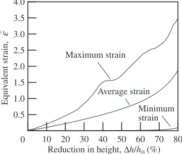
alloy, the upsettability test16)was carried out. In the test, a cylindrical billet was compressed with concentrically grooved flat tools to restrict the end surfaces of the billet, so that the influence of friction between the billet and the tool during the test was removed. The billet deformed to a barrel shape and the equivalent strain in the billet was not distributed uniformly, as shown in Fig. 2 (calculated by FE analysis). The forging limit (forgeability) was defined as the reduction in height of the billet when a crack was first observed on the surface of the compressed billet. Average flow stress was obtained from the load-stroke data in the
upsettability test.17) The average flow stress and average
equivalent strain were calculated by a finite element simulation from the measured load and reduction in height in the experiment. Since it was possible to measure the flow stress curve up to an average equivalent strain of about 2.5 under a high strain rate corresponding to the value in forging process by mechanical press, the test is a practical one for developing forging processes in industry.
The initial shape of billet was cylinder with a diameter
d0of 10 mm and a heighth0 of 15 mm. In extrusion rod, its
axis is corresponded to the billet axis. The billets were heated in a furnace without protective gas and were compressed in
the temperature range of Ts¼473{773K. To prevent the
heated billet from rapidly cooling on the tool, the tools were heated to a temperature of 523 K when the testing
temper-atures were higher than Ts¼523K. For the case of Ts¼
473K, the tools were heated to a temperature of 473 K. The upsettability test was conducted on a material testing machine (Shimadzu Autograph, AG-250kNISE). The com-pression speed was 8.3 mms1; the initial strain rate at the
beginning of compression was about 0.55 s1.
3.2 Forgeability
The as-cast and extruded Mg97Zn1Y2 specimens after
upsetting are shown in Fig. 3. In upsetting of the as-cast
(a) As-cast
(b) 623 K-extruded
(c) 723 K-extruded
Fig. 1 Microstructures of as-cast and extruded Mg97Zn1Y2alloys.
10 20 30 40 50 60 70 80 0.5
1.0 1.5 2.0 2.5 3.0 3.5 4.0
Equi
v
alent strain,
ε
−
Reduction in height, ∆h/h0 (%) Maximum strain
Average strain
0
Minimum strain
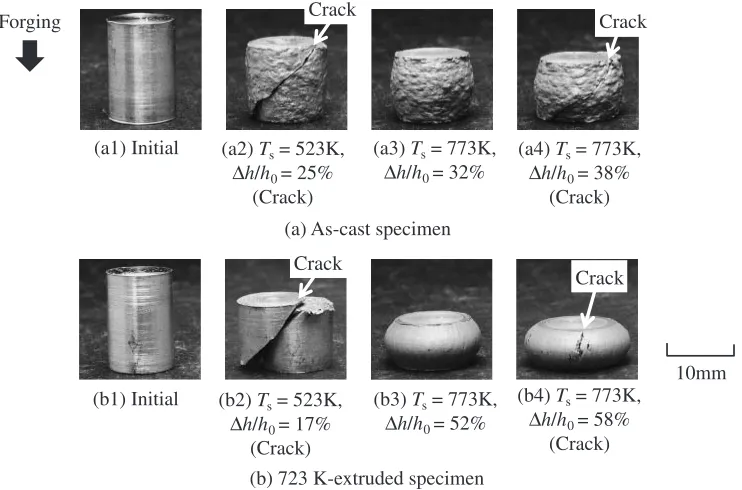
[image:2.595.75.263.73.570.2] [image:2.595.338.518.77.229.2]alloy, a shear type fracture was caused and the barreled surface of the specimen was rough due to the large grain size as shown in Fig. 1. In upsetting of the extruded alloy, the specimen was separated by a shear type fracture at a low reduction in height of h=h0¼17% atTs¼523K. On the
other hand, the ductility was improved atTs¼773K and a
ductile type fracture was caused ath=h0¼58%.
Figure 4 shows the forging limit without fracture of the as-cast and extruded Mg97Zn1Y2 alloys in the upsettability
test. The forging limit of the as-cast alloy was low, i.e.
h=h0¼32% atTs¼773K. Coarse grains and networking
of the LPSO phase in the grain boundaries and dendrite arm boundaries may cause a decline in forgeability. On the other hand, in upsetting of the 623 K-extruded alloy, a shear type
fracture occurred at less than h=h0¼20% irrespective
of the forging temperature. Local grain-refinement and the
formation of hot-worked grains in the-Mg phase, and the
dispersion of the LPSO phase, occurred in extrusion and are thought to be responsible for the low forging limit. In upsetting of the 723 K-extruded alloy, although the forging
limit was low at below Ts¼623K, the ductility changed
discontinuously between Ts¼623K and 723 K, and the
fracture mode changed from the shear type to the ductile type. In comparison with the 623 K-extruded alloy after
forging, the recrystallization of -Mg phase in the 723
K-extruded specimen was accelerated with improving the forgeability. Thus it is found that the forgeability is sensitively affected by the extrusion temperature of the specimen before forging.
[image:3.595.114.485.74.319.2]3.3 Flow stress curve
Figure 5 shows the average flow stress curves of the as-cast and extruded Mg97Zn1Y2alloys obtained from the
load-stroke data in upsetting, prior to the occurrence of a crack in the billet, at various forging temperatures. At the same initial billet temperature, the flow stress values of the extruded billets (Fig. 5(b), (c)) were higher than those of the as-cast ones (Fig. 5(a)), and the peak value of the flow stress of the extruded billets changed considerably with temperature. In
the Mg97Zn1Y2 alloy, it was confirmed that the grain
refinement by extrusion as shown in Fig. 1 is highly effective to strengthening at low temperature and to ductility ment at high temperature. Especially, the ductility improve-ment of 723 K-extruded billet at high forging temperature as shown in Figs. 4 and 5 may be due to expansion of
recrystallized-Mg matrix region and then grain growth of
recrystallized grains during extrusion.
3.4 Vickers hardness
Figure 6 shows the Vickers hardness of the as-cast and extruded Mg97Zn1Y2specimens after forging atTs¼723K. The Vickers hardness was measured at the center of the
(b1) Initial (b2) Ts= 523K, ∆h/h0= 17%
(Crack)
(b3) Ts= 773K, ∆h/h0= 52%
(b4) Ts= 773K, ∆h/h0= 58%
(Crack) (a1) Initial (a2) Ts= 523K,
∆h/h0= 25% (Crack)
(a3) Ts= 773K, ∆h/h0= 32%
(a4) Ts= 773K, ∆h/h0= 38%
(Crack)
(a) As-cast specimen
(b) 723 K-extruded specimen
10mm
Forging Crack
Crack
Crack
Fig. 3 Photographs of as-cast and extruded Mg97Zn1Y2specimens after upsetting.
450 500 550 600 650 700 750 800 0
10 20 30 40 50 60 70 80
Reduction in height,
∆
h/h
0
(%)
Billet initial temperature, Ts /K As−cast
623K−extruded 723K−extruded
A
v
erage equi
v
alent strain,
ε
− ave
0.5 1.0 1.5 2.0
0
[image:3.595.66.270.372.528.2]cross-section in the forging direction. In compression up to an average equivalent strain of 0.8, the hardness of the as-cast and extruded specimens increased to 90 HV and 95 HV, respectively.
[image:4.595.306.549.71.393.2]4. Microstructure
Figure 7 shows optical micrographs of typical cross-sections of the Mg97Zn1Y2specimens forged atTs¼723K.
The forged alloys consisted of two phases, the-Mg matrix
and the LPSO phase, and no phase transformation or formation occurred during forging. However, it has been shown that feature deformation occurred in each phase
during forging. In the comparatively coarse -Mg matrix
grains of the as-cast and 623 K-extruded specimens after forging, profuse twins were observed. However, in the LPSO phase region, twinning was not found and some kink-deformation bands were observed. Arrowheads and arrows in
Fig. 7 indicate representative twin deformation in the-Mg
phase and kink deformation in the LPSO phase, respectively.
In the recrystallized -Mg grains of the 723 K-extruded
specimen after forging, a small number of twins was observed, while kink-deformation bands were frequently observed around the LPSO phase region.
As mentioned above, the microstructures of forged
Mg97Zn1Y2 alloy were characterized by twin deformation
in the-Mg matrix coarse grain region and kink-deformation
in the LPSO phase region. Twin deformation in Mg-Zn-Y alloy was considered to be a supplementary deformation
mechanism of a strong anisotropic dislocation slip,18) and
cannot bring about a sufficiently uniform deformation during forging. In order to avoid macroscopic strain localization
0.2 0.4 0.6 0.8 1.0 1.2 50
100 150 200 250 300 350 400
A
v
erage flo
w stress,
σ
− ave
/MP
a
Average equivalent strain, ε−ave
Ts = 473K
Ts = 573K
Ts = 673K
Ts = 773K
0
(a) As-cast
(b) 623 K-extruded
(c) 723 K-extruded
0.2 0.4 0.6 0.8 1.0 1.2 50
100 150 200 250 300 350 400
A
v
erage flo
w stress,
σ
− ave
/MP
a
Average equivalent strain, ε−ave
Ts = 473K
Ts = 573K
Ts = 673K
Ts = 773K
0
0.2 0.4 0.6 0.8 1.0 1.2 50
100 150 200 250 300 350 400
A
v
erage flo
w stress,
σ
− ave
/MP
a
Average equivalent strain, ε−ave
Ts = 473K
Ts = 573K
Ts = 673K
Ts = 773K
0
Fig. 5 Natural flow stress curves of as-cast and extruded Mg97Zn1Y2 alloys.
0.2 0.4 0.6 0.8 1.0 1.2 70
75 80 85 90 95 100
Average equivalent strain, ε−ave
V
ick
ers hardness (HV0.2)
As−cast 723K−extruded
0
Fig. 6 Vickers hardness of as-cast and extruded Mg97Zn1Y2 specimens after forging atTs¼723K.
(a) As-cast (∆h/h0= 45 %)
(b) 623 K-extruded (∆h/h0= 22 %)
(c) 723 K-extruded (∆h/h0= 45 %)
Fig. 7 Optical micrographs of typical cross-sections of as-cast and extruded Mg97Zn1Y2specimens after forging atTs¼723K (arrowheads:
[image:4.595.80.262.74.473.2] [image:4.595.76.259.526.683.2]slip in the recrystallized fine grains region. As shown in Fig. 4, forgeability of the Mg97Zn1Y2 alloy was sensitively
affected by the extrusion temperature of the alloy before forging. The extruded Mg97Zn1Y2 alloys had three regions,
the dynamically recrystallized -Mg grains region, the
hot-worked -Mg grains region and the kink-deformed LPSO
phase region. Higher temperature extrusion increased the
area fraction of dynamically recrystallized-Mg fine-grains
and decreased that of the hot-worked -Mg region in the
Mg97Zn1Y2 alloys (Fig. 1), resulting in enhancement of
forgeability. Furthermore, as shown in Fig. 5, the flow stress curves in forging showed a tendency towards work harden-ing, although apparent softening by temperature rise during forging was observed in a few forged specimens. Formation
of a kink-deformation band in the LPSO phase and -Mg
phase region may strengthen the Mg alloys,13)because macro kink deformation bands that were formed perpendicular to the primary slip direction19)became an obstruction to basal slipping.
5. Finite Element Simulation to Determine Isothermal Flow Stress Curve
5.1 Isothermal flow stress curve
It is difficult to compress the billet isothermally at a practical forging speed, because the billet temperature is changed during upsetting by heat generation in the billet and heat transfer from the billet surface. The influence of the temperature change on the flow stress must be considered to accurately obtain the flow stress curve. In this study, the flow stress curve, including the temperature change obtained in Fig. 5, is called a natural flow stress curve. To estimate the isothermal flow stress without the influence of the temperature change from the natural flow stress curves, a calculation method for the isothermal flow stress proposed by Kada et al.14)was applied in this study. In this method, the isothermal flow stress was calculated by combining experimental results from the upsettability test with finite element analysis.
5.2 FE simulation conditions
The rigid-plastic finite element method, RIPLS-Forge20)
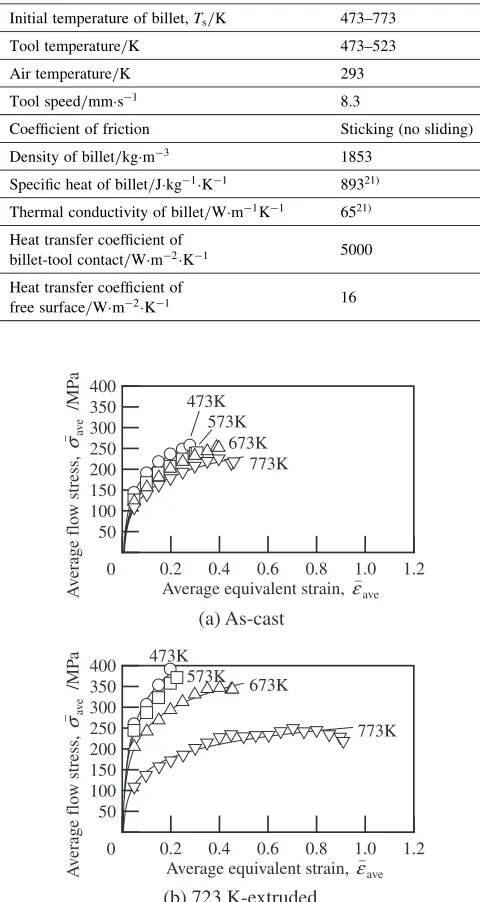
was employed to calculate the load during the upsettability test, and the temperature distribution was calculated by the finite element simulation for heat conduction. In the simulation, the rigid-plastic and the heat conduction finite element calculations were carried out alternately. Table 1 shows the computational conditions used for the simulation of the upsettability test. The dimensions, geometries and temperatures of the billet and tools used for the simulation were set to be the same as the experimental conditions. Specific heat and thermal conductivity used in this simulation
were quoted from previous report.21) Heat transfer
coeffi-cients of billet-tool contact and free surface were determined by the experimental heating test of the specimen, and the frictional condition of the billet-tool interface was assumed to be sticking (no sliding) because a concentrically grooved dies were used in the experiment. The natural flow stresses obtained from experiment at different forging temperatures
(Fig. 5) were employed in the first step of estimating the isothermal flow stresses.
5.3 Calculated isothermal flow stress curves
The isothermal flow stress curves of Mg97Zn1Y2 alloys
calculated from the natural flow stress curves at various forging temperatures are shown in Fig. 8. The isothermal flow stress curves showed a tendency towards work harden-ing. The values of the isothermal flow stress were higher than the natural ones. This indicates the billet temperature was raised by heat generation during upsetting.
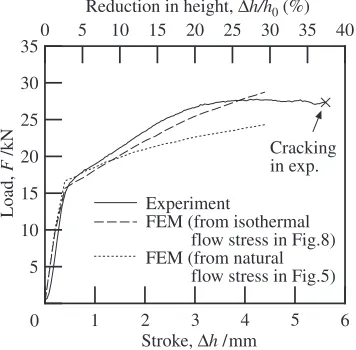
To verify the validity of the calculated isothermal flow stress curve, the histories of the upsetting load and stroke in experiment and finite element simulation of extruded
Mg97Zn1Y2 alloy were compared as shown in Fig. 9. The
load-stroke curves were calculated by using the isothermal
Initial temperature of billet,Ts/K 473–773
Tool temperature/K 473–523
Air temperature/K 293
Tool speed/mms1 8.3
Coefficient of friction Sticking (no sliding)
Density of billet/kgm3 1853
Specific heat of billet/Jkg1K1 89321Þ
Thermal conductivity of billet/Wm1K1 6521Þ
Heat transfer coefficient of
billet-tool contact/Wm2K1 5000
Heat transfer coefficient of
free surface/Wm2K1 16
0.2 0.4 0.6 0.8 1.0 1.2 50
100 150 200 250 300 350 400
A
v
erage flo
w stress,
σ
− ave
/MP
a
Average equivalent strain, ε−ave 0
473K
573K 673K
773K 0.2 0.4 0.6 0.8 1.0 1.2 50
100 150 200 250 300 350 400
A
v
erage flo
w stress,
σ
− ave
/MP
a
Average equivalent strain, ε−ave 0
473K 573K
673K 773K
(a) As-cast
(b) 723 K-extruded
[image:5.595.303.549.94.249.2](Fig. 8(b)) and the natural flow stress curves (Fig. 5(c)) in the finite element simulation. It can be seen that the load history calculated by using the isothermal flow stress curves agrees fairly well with the experimental one.
For the purpose of highly accurate FE analysis for plastic deformation, it is vital to obtain an accurate flow stress curve. From the above results, it is expected that FE analysis for the plastic deformation of the Mg97Zn1Y2 alloys can be
carried out by inputting the calculated isothermal flow stress curves as material properties.
6. Conclusions
To develop a forging process for high strength Mg-Zn-Y alloys with LPSO structure, the forging properties of Mg97Zn1Y2alloy were examined with the upsettability test.
The following results were obtained.
(1) As-cast and 623 K-extruded Mg97Zn1Y2 specimens
were separated by shear type fracture at low reductions in height. In upsetting of 723 K-extruded specimens, the fracture mode changed from shear type to ductile type at upsetting temperature around 673 K.
(2) The isothermal flow stress curves of Mg97Zn1Y2alloy,
which was obtained by removing the influence of the temperature change during upsetting, was accurately estimated by incorporating experimental results in a finite element simulation.
(3) The isothermal flow stress curves of Mg97Zn1Y2 alloy
under high strain rate compression at 473–773 K indicated a tendency towards work hardening.
(4) An increase in the recrystallized -Mg matrix grain
region in the extruded Mg97Zn1Y2 alloys improved
forgeability of the alloys.
Acknowledgement
This work was supported by the Kumamoto Prefecture Collaboration of Regional Entities for the Advancement of Technological Excellence, JST.
REFERENCES
1) B. L. Mordike and T. Ebert: Mater. Sci. Eng. Series A302(2001) 37–45.
2) R. Matsumoto and K. Osakada: Annals CIRP51(2002) 223–226. 3) R. Matsumoto and K. Osakada: Mater. Trans.45(2004) 2838–2844. 4) R. Matsumoto, T. Kubo and K. Osakada: Annals CIRP56 (2007)
293–296.
5) Y. Kawamura, K. Hayashi, A. Inoue and T. Masumoto: Mater. Trans.
42(2001) 1172–1176.
6) E. Abe, Y. Kawamura, K. Hayashi and A. Inoue: Acta Mater.50(2002) 3845–3857.
7) D. H. Ping, K. Hono, Y. Kawamura and A. Inoue: Philos. Mag. Lett.82
(2002) 543–551.
8) T. Itoi, T. Seimiya, Y. Kawamura and M. Hirohashi: Scr. Mater.51
(2004) 107–111.
9) Y. Kawamura and S. Yoshimoto: Magnesium Technology 2005, (TMS, 2005) pp. 499–502.
10) M. Yamasaki, M. Sasaki, M. Nishijima, K. Hiraga and Y. Kawamura: Acta Mater.55(2007) 6798–6805.
11) Y. Kawamura and M. Yamasaki: Mater. Trans.48(2007) 2986–2992. 12) S. Yoshimoto, M. Yamasaki and Y. Kawamura: Mater. Trans. 47
(2006) 959–965.
13) M. Yamasaki, T. Anan, S. Yoshimoto and Y. Kawamura: Scr. Mater.
53(2005) 799–803.
14) O. Kada, T. Miki, M. Toda and K. Osakada: Annals CIRP47(1998) 185–188.
15) M. Yamasaki, H. Tamagawa, Y. Kawamura, K. Hagihara, Y. Umakoshi, T. Morikawa and K. Higashida: in preparation.
16) H. Kudo, K. Sato and K. Aoi: Annals CIRP16(1968) 309–318. 17) K. Osakada, T. Kawasaki and K. Mori: Annals CIRP30(1981) 135–
138.
18) J. Koike: Metall. Mater. Trans.36A(2005) 1689–1696.
19) K. Higashida, J. Takamura and N. Narita: Mater. Sci. Eng.81(1986) 239–258.
20) K. Osakada, J. Nakano and K. Mori: Int. J. Mech. Sci. 24(1982) 459–468.
21) M. Yamasaki and Y. Kawamura: Scr. Mater.60(2009) 264–267.
1 6
5 10 15 20 25 30 35
0 5 10 15 20 25 30 35 40 Reduction in height, ∆h/h0 (%)
Load,
F
/kN
Stroke, ∆h /mm 0
Experiment
FEM (from isothermal flow stress in Fig.8) FEM (from natural
flow stress in Fig.5) Cracking in exp.
2 3 4 5
[image:6.595.81.259.76.251.2]