E
ff
ect of Laser Patterning Preprocessing on Fatigue Strength of Adhesive Bonded
Joints Using Thin Steel Plate
+1Katsuki Shikimoto
1, Shogo Ishida
2, Wataru Jinnouchi
2, Yuki Ogawa
3, Hiroyuki Akebono
2,+2and
Atsushi Sugeta
2,+21Mitsui Chemicals, Inc., Kuga-gun, Yamaguchi 740-0061, Japan
2Department of Mechanical Science and Engineering, Hiroshima University, Higashi-hiroshima 739-8527, Japan
3National Institute for Materials Science, Tsukuba 305-0047, Japan
Reducing the weight of automobile bodies would help counteract environmental problems caused by greenhouse gas emissions by improving fuel efficiency. Multi-material structures have been investigated to construct an automobile body structure composed of steel in combination with lightweight metal materials and carbon-fiber-reinforced plastic. Thus, it is necessary to develop high-quality bonding techniques that can join dissimilar materials as quickly as possible. To this end, adhesive bonding has attracted attention from the viewpoint of building multi-material structures. However, from the viewpoint of durability and reliability, it is regarded as a complementary technique used to support other industrial welding methods. Moreover, to further improve the strength of adhesive bonding, the surface conditions of the adherend must be considered. In this study, to improve the interfacial strength of adhesively bonded joints, laser patterning pre-processing was applied as a surface treatment. The fatigue properties of adhesively bonded joints were evaluated and compared with those of untreated joints. It was found that the static and fatigue strengths of the joints were improved by the laser patterning pre-processing. In particular, the joint strength was improved by removing the weak boundary layer from the entire adhesion surface with laser irradiation. Therefore, the laser patterning pre-processing method proposed in this study is a very promising process for achieving adhesively bonded joints with excellent fatigue properties.
[doi:10.2320/matertrans.Z-M2019870]
(Received October 21, 2019; Accepted November 21, 2019; Published February 25, 2020)
Keywords: adhesive bonding, fatigue, laser patterning, surface treatment, anchor effect
1. Introduction
Recently, the automotive industry has had to develop technologies to counteract environmental problems caused by greenhouse gases such as carbon dioxide. As one such solution, the automotive industry has been working to reduce fuel consumption by replacing conventional materials used in automotive design with lightweight resin-based materials of high specific strength, such as light metal materials and carbon-fiber-reinforced plastic (CFRP), for the purpose of manufacturing a multi-material body structure.13)To achieve such a multi-material structure while ensuring a high degree of safety and reliability during actual operation, it is essential to establish technology that can be used to join these different materials.
Among the various joining techniques, adhesive bonding is attracting attention as an effective method. Adhesive bonding is the joining of two objects using an adhesive material. It is advantageous in that there are no restrictions on material selection when joining different materials. In addition, adhesive bonding is expected to show higher strength and rigidity than resistance spot welding, which is currently the most commonly used joining technique for automotive body construction because adhesive bonding is a surface joining technique.29) However, because adhesive bonding is a relatively new joining technique, its strength reliability and fatigue resistance are poorly characterized. Thus, it is currently used as a supporting joining method for other joining techniques.
Therefore, to expand the application range of adhesive bonding, it is necessary to qualify the reliability of the fatigue resistance of adhesively bonded joints. The strength of adhesively bonded joints is affected by factors such as the surface condition of the adherends, including the weak boundary layers; the chemical intermolecular forces between the adhesive and the adherends; and the geometric anchor effect.10,11) The surface properties of the adherends greatly influence the strength of adhesively bonded joints.1214)
In this study, the effect of applying laser patterning treatment1419) to the adherend surface was evaluated. This treatment involves the local and selective removal of the material surface layer in a short time by irradiation of the surface with a high-density laser beam. Furthermore, it is a dry process that requires no pre-processing. Therefore, it has been applied in a wide range of fields, including the microfabrication of electronic equipment.2023) Applying laser patterning to the adherend surface before depositing the adhesive is expected to induce the anchor effect,15)which is caused by the increased surface roughness achieved by laser patterning; increase the adhesive area; and remove weak boundary layers,23)such as oxides, hydrates, and deposits on metal surfaces. As a result, performing laser patterning prior to adhesion is expected to improve the fatigue properties of adhesively bonded joints. However, there are few reports on the application of laser patterning to the adherend surface prior to adhesion and the fatigue properties of the resulting joints.
Therefore, in this study, the effect of laser patterning pre-processing on the fatigue properties of adhesively bonded joints using cold rolled SPCC steel sheets for automotive applications was experimentally evaluated. In addition, different patterns were formed on the adherend surface by applying different processing conditions, and the difference in +1This Paper was Originally Published in Japanese in J. Soc. Mater. Sci.
Japan68(2019) 890896.
+2Corresponding authors, E-mail: akebono@hiroshima-u.ac.jp, asugeta@
hiroshima-u.ac.jp
the effects of different patterning shapes on the fatigue properties of adhesively bonded joints is discussed. Furthermore, the possibility of expanding the application range of the laser patterning pre-processing proposed in this study was addressed through the examination of adhesively bonded joints in stainless steel sheets.
2. Specimens and Experimental Procedures
2.1 Specimens
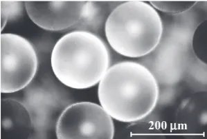
Cold rolled SPCC steel sheets commonly used for automotive parts and austenitic stainless steel sheets of grade SUS316 with a thickness of 1.2 mm were used as adherends in this study. Tables 1 and 2 show the chemical compositions and mechanical properties of these two materials. The test pieces were cut out into 70 mm©25 mm strips, and two sheets were joined such that the overlapping area measured 10 mm in the longitudinal direction, as shown in Fig. 1. The entire overlapping area (10 mm©25 mm) was bonded with adhesive, and the as-prepared sheets were used as a specimen. In addition, in this study, the thickness of the adhesive layer was set to 0.15 mm by mixing 0.15-mm-diameter glass beads (Fig. 2) into the adhesive. Furthermore, their surfaces were ultrasonically cleaned with acetone, regardless of whether they were laser patterned.
The adhesive used in this study was a one-component thermosetting epoxy resin adhesive used in automotive applications (Penguin Cement SW-601, Sunstar Engineering, Inc.). After the adhesive was deposited and the sheets were joined, the adhesively bonded joint was thermally cured with an electric furnace while the specimen was restrained in the thickness direction with a jig (heating speed: 6°C/min, heating temperature: 200°C, heat holding time: 60 min, furnace cooled to room temperature after heating).
2.2 Laser patterning
For laser patterning, the YS-P30 (Sun Instrument) was used, and the laser beam was set to have a wavelength of 1064 mm and a spot diameter of 30 µm. In this study, laser patterning processing was applied to the bonding area of the SPCC (10 mm©25 mm) under two types of laser irradiation conditions, and the effect of the laser patterning on the strength of adhesively bonded joints was examined. Figure 3(a) and (b) show the cross-sectional shapes of metal sheets with laser patterning applied under two different irradiation conditions. In addition, Tables 3 and 4 show the laser irradiation conditions corresponding to the cross sections in Fig. 3(a) and (b), respectively.
The pattern shown in Fig. 3(a) is a relatively deep and large groove pattern, and the purpose of this pattern is to improve the anchor effect by producing unevenness on the adherend surface. In detail, grooves with a width of 0.03 mm and a depth of 0.01 mm were etched in the bonding area
[image:2.595.351.501.70.171.2]Table 1 Chemical composition [mass%].
Table 2 Mechanical properties.
0.15
1.2
2.55
40 10
25
A
A
Bonding area
Chuck part 130
70
Loading direction
A-A cross-section
Fig. 1 Shape and dimensions of the specimens.
200µm
Fig. 2 Glass beads mixed into the adhesive.
(a) Anchor (b) Cleaning 100μm 100μm
Loading direction
Fig. 3 Cross sections of adherends after two types of laser patterning.
[image:2.595.58.264.500.773.2] [image:2.595.314.538.570.674.2] [image:2.595.318.536.730.785.2]at 0.13 mm intervals in the load axis vertical direction. Therefore, under this condition, there remain some unprocessed areas on the metal surface. In contrast, the patterning shown in Fig. 3(b) was designed for the purpose of cleaning the metal surface. In detail, grooves with a width of 0.03 mm and a depth of 0.005 mm were etched in the adhesive-treated area at 0.03 mm intervals in the vertical direction for loading axis. Under this condition, the entire bonding area is processed by the laser patterning. In addition, the laser patterning treatment time in this study is approximately 20 to 30 s under each set of conditions, and the patterning can be performed in a very short time. In this paper, the type of joint with the patterning shown in Fig. 3(a) to achieve the anchor effect is called the anchor joint, and that with the patterning shown in Fig. 3(b) that cleans the metal surface is called the cleaning joint.
Additional specimens were prepared with SPCC sheets that were subjected to laser patterning treatment. Two cases were considered for the untreated joints. In the first, no processing was performed on the sheets, and in the second, the adhesive area was polished with SiC paper (#600#2000) and ultrasonically cleaned with acetone before the adhesive bonding was applied. Joints made under these conditions are hereafter referred to as unprocessed and polished joints, respectively. The laser patterning conditions for the SUS316 are described in a later section.
2.3 Experimental procedure
Static tensile and the fatigue tests were performed using a hydraulic servo pulsar (Shimadzu Corporation) at room temperature under atmospheric conditions. In addition, a jig that can move in the thickness direction of the plate was used tofix the joint, thereby preventing bending stress from acting upon the bonded area. The load speed during the static tensile test was 1.2 N/min. The fatigue test was performed at a frequency of f=120 Hz and a stress ratio of Rp (=Pmin/
Pmax)=0.1. The time when the joint was completely separated into two pieces was defined as the fracture, and a number of test interruptions isN=1©107cycles.
3. Experimental Results and Considerations
3.1 Evaluation of strength characteristics of adhesively bonded joints using SPCC
3.1.1 Static tensile test results
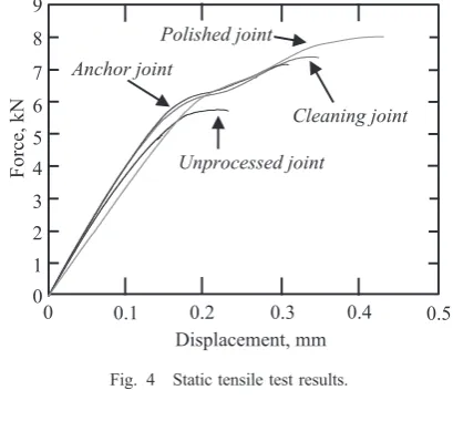
Static tensile tests were conducted three times for each adhesively bonded joint using cold rolled steel SPCC sheets. Figure 4 shows typical test results, and Table 5 gives the average static tensile strength of each type of joint. In Fig. 4, the force acting on the joint is plotted against the piston displacement. Figure 4 and Table 5 show that the static
tensile strengths of the polished, anchor, and cleaning joints were significantly higher than that of the unprocessed joint. Among the four joints, the polished and cleaning joints had the highest static tensile strengths.
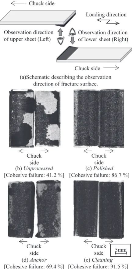
Figure 5 shows images of the fracture surfaces after the static tensile test. In addition, Fig. 5(a) illustrates the observation direction, and along with the fracture surface images, Figs. 5(b)(e) also give the rate of the cohesive failure, which is defined as breaking inside the adhesive. The cohesive failure rate was calculated from the fracture surface observation results as follows. First, the area where the base material is exposed because of interfacial failure (Fig. 5 labels typical examples with white arrows) was measured with a digital microscope, and the interfacial failure rate, which is the ratio of the interfacial failure area to the total adhesion area, was calculated. The cohesive failure rate was then calculated by subtracting the interfacial failure rate from the total adhesion area. In general, a cohesive failure rate tends to produce a joint with greater strength because the rate of interfacial failure between the adherend and adhesive is lower.8,24)
[image:3.595.323.528.73.263.2]The results shown in Fig. 5 suggest that the interfacial strength between the base metal and the adhesive is improved in the polished, anchor, and cleaning joints. This seems to be the mechanism underlying the improvement of the static tensile strength shown in Fig. 4 and Table 5. Furthermore, the areas in which interfacial and cohesive failure occurred on the fracture surface were observed in detail. It was found that in the anchor joint, the failure areas were irregularly mixed. In contrast, in the polished and cleaning joints, interfacial failure occurred only at the bonded edge, where the stress was concentrated, and cohesive failure occurred near the center of the bonding area. This indicates that removing the weak boundary layers in the bonding area may be an effective way to create adhesively bonded joints with a high static tensile strength.
Table 4 Laser patterning conditions for thecleaning joint.
Cleaning joint Polished joint
Unprocessed joint Anchor joint
Displacement, mm
Force, kN
0.4 0
4 6 9
0 0.2
7
2 8
0.1 0.3
5
3
1
0.5
Fig. 4 Static tensile test results.
[image:3.595.61.278.89.142.2]3.1.2 Fatigue test results
Figure 6 shows the fatigue test results for each joint. In Fig. 6, the applied force amplitude Paacting on the joint is plotted against the number of cycles to failure. Figure 6 indicates that the fatigue strength of the polished, anchor, and cleaning joints tend to result in these joints having a longer life than the unprocessed joint. Furthermore, the cleaning and anchor joints had the highest and second highest fatigue strengths of the four joints considered in this study, respectively. Moreover, the degree of fatigue strength improvement of the unprocessed joint was larger than that of the polished joint.
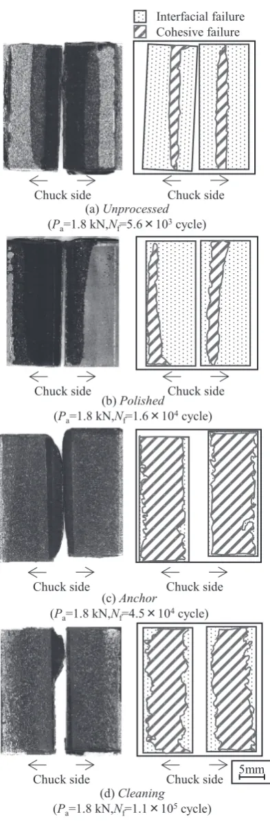
The fracture surface of each joint was observed after fatigue failure to elucidate the factors producing these results. Figure 7 shows the results of the observation. The observation direction is the same as in Fig. 5(a). The left side of each part of Fig. 7 shows an image of the fatigue fracture surface, and the right side schematically shows the areas where interfacial and cohesive fracture occurred. The
cohesive failure rate of all fractured joints was calculated, and the average cohesive failure rate was obtained for each joint. The average cohesive failure rates were 30.2%, 31.7%, 66.5%, and 65.6%for the unprocessed, polished, anchor, and cleaning joints, respectively. In addition, the cohesive failure rates of the anchor and cleaning joints, which were subjected to laser patterning, were significantly higher than those of the unprocessed and polished joints.
This seems to have been caused by the improvement of the interfacial strength between the adherend and the adhesive.15) This improvement was a result of the anchor effect, which was achieved through the fine surface roughness formed by laser patterning. This type of interfacial strength improve-ment through patterning is considered to have remarkably suppressed the occurrence of interfacial failure, which causes strength reduction. As a result, it appears that a transition in the fracture mode to cohesive failure produced the higher fatigue strength in the joints subjected to patterning. Furthermore, in the cleaning joint, the high cleanliness23) of the material achieved by removing the weak boundary layers from the entire surface of the bonding area also had a positive effect on the strength. As a result, the cleaning joint showed the best fatigue strength among the considered joint types. These results indicate that the laser patterning used in this study is an effective pre-processing method for adhesively bonded joints. In addition, the average cohesive failure rates of the fatigue fracture surfaces of the polished and cleaning joints were much lower than those of the static fracture surfaces. In particular, the cleaning effect seems to have had a large effect under static loading but little effect under dynamic loading. In contrast, the average cohesive failure rate of the anchor joint was not significantly different in the static and fatigue loading cases. This indicates that the effects of anchor and cleaning patterning types on joint strength depend on whether the loading is static or dynamic. This will be an avenue for future investigation.
3.2 Effect of laser patterning pre-processing on the
fatigue strength of adhesively bonded joints in SUS316
The investigations described in the previous section experimentally revealed that applying laser patterning pre-(b) Unprocessed
[Cohesive failure: 41.2 %]
Chuck side Chuck
side
5mm Chuck
side Chuck
side
(c) Polished [Cohesive failure: 86.7 %]
(d) Anchor [Cohesive failure: 69.4 %]
(e)Cleaning [Cohesive failure: 91.5 %] Chuck side
Chuck side
Observation direction of lower sheet (Right) Observation direction
of upper sheet (Left)
(a)Schematic describing the observation direction of fracture surface.
Loading direction
Fig. 5 Fracture morphologies after static tensile test.
Unprocessed
Cleaning joint Anchor joint Polished joint
102 103 104 105 106 107 0
Number of cycles to failure,Nf(cycles)
F
orce am
plitu
de
,
Pa
(kN)
2.5
2.0
1.5
1.0
0.5
[image:4.595.61.278.70.513.2] [image:4.595.324.529.70.235.2]processing to the bonding area is extremely effective for the improvement of the fatigue properties of adhesively bonded joints in cold rolled SPCC steel sheets for automotive applications.
For the purpose of expanding the range of application of the recommended process for laser patterning, an exper-imental study on adhesively bonded joints in austenitic
stainless steel sheets of grade SUS316 was conducted. The laser irradiation conditions for this experiment were the same as for the preparation of the cleaning joint, which showed excellent fatigue properties. Moreover, for the sake of comparison, the same experiments were conducted on the unprocessed joint type.
First, the groove shape formed on the SUS316 surface was compared with that of SPCC when the processing was applied to SUS316 under the same conditions as the cleaning joint described in the previous section (Table 4).
[image:5.595.70.267.64.662.2]Figure 8 shows the observation results, which indicate that there is no significant difference in the width and depth of the grooves between the two target adherends. However, regarding the convexity of the groove, the groove formed on the surface of the SUS316 was sharper than that for the SPCC.
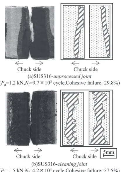
Figure 9 shows the fatigue test results of the SUS316 unprocessed and cleaning joints. In addition, Fig. 9 includes the test results for the SPCC unprocessed and cleaning joints shown in the previous section for the sake of comparison. Moreover, Fig. 10 shows the fracture surface observation results after the fatigue test. In addition, the observation direction of the fatigue fracture surface is the same as in the previous section.
According to the fatigue test results, the fatigue strength of the SUS316 cleaning joint resulted in this specimen having a longer life than of the SUS316 unprocessed joint, which is the same as in the case of SPCC. From the fracture surface (b) Polished
(Pa=1.8 kN,Nf=1.6×10⁴cycle) Interfacial failure
Chuck side
(a) Unprocessed (Pa=1.8 kN,Nf=5.6×10³cycle)
Cohesive failure
Chuck side
Chuck side Chuck side
(c) Anchor
(Pa=1.8 kN,Nf=4.5×10⁴cycle)
(d)Cleaning
(Pa=1.8 kN,Nf=1.1×10⁵cycle)
5mm Chuck side Chuck side
Chuck side Chuck side
Fig. 7 Fatigue fracture surfaces of each type of joint.
(a) SPCC (b)SUS316
20μm Loading direction
20μm
Fig. 8 Cross sections of adherends after laser patterning for two different materials.
SPCC-Unprocessed SUS316-Unprocessed SPCC-Cleaning SUS316-Cleaning
102 103 104 105 106 107 0
Number of cycles to failure,Nf(cycles)
Force
am
plitude,
Pa
(k
N
)
2.5
2.0
1.5
1.0
0.5
[image:5.595.313.534.71.183.2] [image:5.595.317.536.221.393.2]observation results shown in Fig. 10, the cohesive failure rate of the SUS316 cleaning joint was larger than that of the SUS316 unprocessed joint. It was thus concluded that interfacial strength improvement due to patterning greatly suppresses interfacial failure, which causes strength reduc-tion; this leads to excellent fatigue properties, as also discussed in the previous section.
In addition, despite the same laser irradiation conditions being used for the two materials, the fatigue strength improvement of the adhesively bonded joints relative to the strength of the corresponding unprocessed joint was different for the two types of materials. Namely, the effect of laser patterning for SPCC seems to be greater than that for SUS316. This is likely because the chemical bond strength between the adherend and the adhesive depends on the adherend material because of differences in the chemical composition at the adherend surface; as mentioned above, the groove formed on the surface of SUS316 is sharper than that for SPCC, and the local high stress produced by this greater sharpness is applied to the adhesive layer. In addition, the surface roughness of the adherend greatly affects the strength of adhesively bonded joints, but it has been reported that the most suitable surface roughness depends on the type of adherend.25)This will be the focus of future work.
In conclusion, this study has revealed that the type of laser patterning pre-processing proposed in this study is widely effective as a method of improving the fatigue strength of adhesively bonded joints using various steel materials.
4. Conclusions
This study focused on laser patterning pre-processing of the surface of an adherend to improve the fatigue reliability of adhesively bonded joints. An experimental study on the effect of laser patterning pre-processing on the fatigue properties of adhesively bonded joints was conducted using various steel materials, and the usefulness of this approach was considered. The conclusions of this study are as follows. (1) Applying laser patterning pre-processing to the bonding area prior to adhesive bonding significantly improves the static and fatigue strength of the bond in comparison with normal adhesively bonded joints.
(2) The groove formed on the surface of the adherend by laser patterning pre-processing produces an anchor effect and produces a cleaning effect because the weak boundary layer is removed by the laser irradiation, which then increases the interfacial strength between the base metal and the adhesive. As a result, excellent fatigue properties can be obtained.
(3) The laser patterning pre-processing proposed in this study is a very promising process for achieving adhesively bonded joints with excellent fatigue proper-ties regardless of the type of adherend.
REFERENCES
1) R. Sakano:J. Jpn. Weld. Soc.81(2012) 159163.
2) Y. Kitaoka:J. Jpn. Weld. Soc.83(2014) 510.
3) T. Anami:J. Surf. Finish. Soc. Jpn.67(2016) 639643.
4) M. Ide:J. Jpn. Weld. Soc.60(1991) 219226.
5) M. Yoneno:Tetsu-to-Hagané77(1991) 11691176.
6) T. Ashida:J. Jpn. Weld. Soc.70(2001) 248252.
7) Y. Okuri:J. Jpn. Weld. Soc.73(2004) 211215.
8) K. Haraga:J. Adhes. Soc. Jpn.43(2007) 319324.
9) Y. Okuri:J. Jpn. Weld. Soc.66(1997) 8185.
10) C. Sato:J. Surf. Finish. Soc. Jpn.67(2016) 644648.
11) E. Yanagihara:J. Jpn. Weld. Soc.70(2001) 409415.
12) O. Sakata, Y. Usui, M. Simamoto, K. Kohno, Y. Kinosita and K. Miyasita:J. Jpn. Soc. Precis. Eng. Supplement. Contributed papers64
14921496 (1998).
13) S. Yoshida, K. Kihara, H. Isono and T. Sugibayashi:J. Adhes. Soc. Jpn.
49(2013) 197203.
14) H. Oguma and K. Naito: Proceedings of the 34th Symposium on Fatigue, No. 21, (The Society of Materials Science, Japan, 2018). 15) R. Kromer, S. Costil, J. Cormier, D. Courapied, L. Berthe, P. Peyre and
M. Boustie:Surf. Coat. Tech.278(2015) 171182.
16) T. Yokozeki, M. Ishibashi, Y. Kobayashi, H. Shamoto and Y. Iwahori:
Adv. Compos. Mater.25(2016) 317327.
17) G. Rotella, L. Orazi, M. Alfano, S. Candamano and I. Gnilitskyi:CIRP
J. Manuf. Sci. Technol.18(2017) 101106.
18) R. Tao, M. Alfano and G. Lubineau:Compos., Part A109(2018) 84 94.
19) C. Leone and S. Genna:Compos. Struct.194(2018) 240251.
20) A. Matsunawa:J. Inst. Electr. Eng. Jpn.113919921 (1993).
21) T. Ueno and T. Yokoi:J. Jpn. Soc. Precis. Eng.68(2002) 12871289.
22) S. Ishida, W. Jinnouchi, H. Akebono and A. Sugeta: Proceedings of the 67th JSMS Annual Meetings, (The Society of Materials Science, Japan, 2018) pp. 277278.
23) Y. Minamizaki:J. Jpn. Inst. Electr. Packag.6(2003) 349354.
24) K. Haraga:J. Adhes. Soc. Jpn.50(2014) 5358.
25) A. Ghumatkar, R. Sekhar and S. Budhe:Mater. Today Proc.4(2017) 78017809.
(a)SUS316-unprocessed joint
(Pa=1.2 kN,Nf=9.7×10³cycle,Cohesive failure: 29.8%)
(b)SUS316-cleaning joint
(Pa=1.5 kN,Nf=4.2×10⁴cycle,Cohesive failure: 57.5%) 5mm Chuck side Chuck side
[image:6.595.67.274.66.360.2]Chuck side Chuck side