Microstructural Evolution and Hardness of Dissimilar Lap Joints
of ODS
/
Stainless Steel by Friction Stir Welding
Chun-Liang Chen
1,+, Asta Richter
2, Lung-Tien Wu
3and You-Ming Dong
41Department of Materials Science and Engineering, National Dong Hwa University, Hualien 97401, Taiwan, R. O. China 2Department of Engineering, Technical University of Applied Sciences Wildau, Bahnhofstrasse 1, 15745 Wildau, Germany 3Metal Industries Research & Development Centre, Kaohsiung City 811, Taiwan, R. O. China
4Department of Materials Science and Engineering, I-Shou University, Kaohsiung City 84001, Taiwan, R. O. China
Ferritic oxide dispersion strengthened (ODS) alloy and stainless steel are attractive candidates for applications in the high temperature industries. Friction stir welding (FSW) is a very promising technique for the joining of both materials. Severe shear deformation and high heat input during FSW process can significantly change the microstructure and material property of the joints. The joint quality therefore plays a decisive role in material performance, life expectancy and cost. In this study, the different joints between ODS alloy and stainless steel were investigated in three different zones: the thermo-mechanically affected zone, the heat affected zone and the base material. Phase transformations and chemical reactions in the case of dissimilar welds were also studied. Electron backscattering diffraction (EBSD) was used to analyze the grain orientation, the grain boundary geometries and recrystallization behavior. Hardness changes within the welding zones and variation with grain boundary angle are discussed. [doi:10.2320/matertrans.M2012281]
(Received August 16, 2012; Accepted October 31, 2012; Published January 25, 2013)
Keywords: nanostructure material, oxide dispersion strengthened (ODS) alloys, ferritic stainless steel, friction stir welding (FSW), electron backscatter diffraction (EBSD)
1. Introduction
Fe-based oxide dispersion strengthened (ODS) alloys
containfine and uniformly dispersed yttrium oxide particles
in a ferritic matrix. The high temperature stability of the nano-oxide dispersoids act as pinning points to inhibit dislocation movement and provide excellent creep strength
and irradiation resistance.13) Therefore, these materials are
of potential use in advanced energy generation such as
hydrogen fuel cells and fission/fusion nuclear reactors.46)
In addition, type 430 is the most widely used of the ferritic stainless steels. It exhibits excellent high temperature oxidation resistance, good weldability, corrosion resistance and low cost. Ferritic stainless steel is another candidate
material for use in the blanket of nuclear reactors.7,8)
However, both materials are difficult to weld by conventional
fusion welding processes. For ODS alloys, agglomeration
of fine oxide particles would result in loss of strength in
the ODS joints. For 430 stainless steel, it can lead to grain coarsening, stress corrosion cracking (SSC), and the formation of delta ferrite in the welded region, reducing
toughness, ductility and corrosion resistance.9) Friction stir
welding (FSW) is an advanced joining technique in which the material is welded with a low heat input and undergoes extreme plastic deformation in the solid state. It is therefore recommended as one of the most promising welding methods used to join high melting temperature materials (e.g.,
stainless steels and ODS alloys).1014)In this study, dissimilar
lap joints of 430 stainless steel and ferritic ODS alloys were investigated. Microstructures and mechanical properties of the FSW material were studied in different zones, including the base material (BM), the thermo-mechanically affected zone (TMAZ) and the heat affected zone (HAZ). EBSD was performed to investigate the mixed structure of the grain
orientation, grain size distribution and grain boundary angle associated with recrystallization and recovery behavior of materials.
2. Experimental Procedures
Two materials used in this study are Fe-based ODS alloys and commercial 430 stainless steels. The ODS alloy was manufactured by the mechanical alloying process in a high-energy ball mill. The raw powders were mixed together to
control the mean composition to be Fe20Cr5.5Al0.5Ti
0.5Y2O3(mass%). The milled powders were then compacted
and subjected to hot-extrusion and hot-rolling at temperatures between 900 and 1150°C to produce a 2 mm thick sheet in an elongated grain structure. The commercial 430 stainless
steels contain between 16 and 18% chromium, a maximum
of 0.15% carbon, and very little nickel. Both ODS and
commercial 430 stainless steels were then cut into 20 mm square specimens with a thickness of 2 mm for FSW experiments.
Friction stir spot welding (FSW) is a non-consumable welding technique which does not involve melting of the
materials. This process has the potential to avoid significant
microstructural or mechanical property changes in materials. In this work, the method involves the plunge and retraction of the FSW tool and can be used to weld two sheets for an overlap joint. The rotating pin left a keyhole after the weld completion. In this case, stir zone (SZ) might not be able to see in this process. There are only two microstructural zones created around the pin, thermo-mechanically affected zone (TMAZ) and heat affected zone (HAZ). FSW trials were performed in the friction stir welding laboratory of the Metal Industries Research and Development Centre Taiwan. Four different conditions of FSW joints were investigated in
this study. They include the ODS/ODS joint, the 430/430
joint, the 430/ODS joint and the ODS/ODS joint after
+Corresponding author, E-mail: chunliang@mail.ndhu.edu.tw Materials Transactions, Vol. 54, No. 2 (2013) pp. 215 to 221
recrystallization heat treatment at 1380°C for 1 h, named
HT-ODS/ODS, respectively. The HT-ODS/ODS sample would
be useful to understand the process of recrystallization associated with the change of angle grain boundaries. Two pieces of 2 mm thick sheets were friction stir welded by plunging the tool into the overlap joint, leaving a keyhole after the weld completion. An FSW machine with the plunge
rate from 1.2 to 4.8 mm/min was used. Rotation speed,
plunge depth and dwell time were fixed at 1200 rpm, 3 mm
and 5 s, respectively. The microstructure of the welded joints was examined using a Hitachi-4700 Scanning Electron Microscope (SEM). A JEOL-6330 Field Emission SEM equipped with EBSD was used to analyze the grain orientation, the grain boundary geometries and recrystalliza-tion behavior. All crystallographic orientarecrystalliza-tion data were collected by electron backscatter patterns and processed using the software package CHANNEL 5. Additionally,
X’PERT PRO X-ray diffraction (XRD) with Cu K¡radiation
was used to determine the complex phases in the FSW joints. Vickers hardness measurements were performed at room temperature using a load of 10 N for 15 s.
3. Results and Discussion
3.1 The ODS/ODS joint
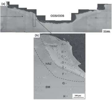
Figure 1(a) shows an optical micrograph of the
macro-structure of the ODS/ODS joint. The shape of the weld
cross-section corresponds to the tool geometry of FSW (a pin
and shoulder profile). The FSW weld area consists of the
thermo-mechanically affected zone (TMAZ), the heat-affected zone (HAZ) and the unheat-affected base material zone
(BM). Three zones are visible and can be identified by
Vickers hardness measurements. The enlarged image in Fig. 1(b) shows a row of Vickers hardness indents labeled by A to H. The corresponding hardness values are displayed in Table 1. During the FSW process, the microstructure and hardness of as-received ODS materials are changed. Indents B to E are located in the TMAZ and have a lower hardness
value (³276 HV) than the BM. During the FSW process,
dynamic recrystallization appears with the formation of a
fine-equiaxed grain structure with low dislocation
den-sity.13,15) Figure 2 shows SEM images in the TMAZ, HAZ
and BM regions. It is obvious that the microstructure changes
[image:2.595.117.479.66.389.2]Fig. 1 Optical microscopy image of the cross section of the ODS/ODS joint: (a) overview and (b) detail with Vickers indent row across the welding zones.
Table 1 Vickers hardness indent rows with respect to Figs. 1, 3, 6 and 8 with marked location of the indent, the corresponding HV value and attribution to the welding zones.
ODS/ODS HT-ODS/ODS 430/430 430/ODS
A 290 238 330 316
B 275 234 245 285
C 279 236 279 187
D 271 253 360 189
E 280 288 ® 220
F 304 305 ® 270
G 318 ® ® 305
[image:2.595.304.550.480.589.2]from the elongated grains in the BM to the equiaxed grains in the TMAZ. This implies that severe plastic deformation with simultaneous high temperature during friction stir welding
induced significant changes in the microstructure.
The large amount of mechanical deformation at elevated temperatures during the FSW process can encourage dynamic recrystallization. The recrystallized grains with equiaxed grain structure are mainly separated by high angle grain
boundaries.13)Indent F marks the heat-affected zone (HAZ)
with a larger hardness value of 304 HV. In the HAZ region, a partially recrystallized grain structure develops with the structural transfer from elongated grains with low angle boundaries in the base material towards equiaxed grains with high angle boundaries. Indents G and H are in the base material and far away from the FSW region, which indicate the highest hardness value of 321 HV on average for all three zones. This region contains the elongated grains, which consist of numerous subgrains with low angle boundaries. Additionally, a high concentration of tungsten at the area of the indent A has been determined by energy dispersive X-ray (EDX) analysis, which results in a slight increase in hardness at the indent A (290 HV). This means, that the friction tool made of a tungsten alloy is undergoing an abrasive process during FSW and is mechanically implanted in the joint material.
[image:3.595.65.272.68.274.2]3.2 The HT-ODS/ODS joint
Figure 3 shows the microstructure of the ODS/ODS
joint after recrystallization treatment at 1380°C for 1 h in laboratory air. Large recrystallized grains were observed in the TMAZ region, which implies that after further heat treatment, the thermo-mechanical processing provides a large driving force for secondary recrystallization. The size of the secondary recrystallized grains (>200 µm) is much larger
than that of the dynamically recrystallized grains (³5 µm)
which formed during FSW process. The hardness of the secondary recrystallized grains (Indents A to C) also shows
the lowest hardness (³236 HV), see Table 1. Indents marked
by D and E in Fig. 3(b) belong to the HAZ region and show
a higher hardness value (³270 HV). A number of small
Fig. 2 SEM images of the ODS/ODS joint in the (a) TMAZ, (b) HAZ and (c) BM regions.
Fig. 3 Optical microscopy image of the cross section of the ODS/ODS joint after annealing at 1380°C for 1 h: (a) overview and (b) detail with Vickers indent row across the welding zones.
[image:3.595.114.485.467.760.2]dynamically recrystallized grains were found at the HAZ. EBSD was used to investigate the grain orientation and the grain boundary geometries in this region (Fig. 4). The EBSD orientation map, Fig. 4(b), exhibits distinct grains with varied grain orientations highlighted with different colors. The average size of the grains is about 5 µm. The grain boundary misorientation angle map, Fig. 4(c), reveals important details of the sub-structure. The high energy, high-angle boundaries are decorated with gray lines (misorientations between 2 and
15°) and black lines (for misorientations >15°). The results
demonstrate that high angle boundaries can be seen to comprise the majority of the boundaries in this region, suggesting recrystallization occurs during FSW. It is clear that any inhomogeneity of stored energy would affect the
nucleation of recrystallization.15)Indent F in Fig. 3(b) with a
hardness of 305 HV is in the area of the bulk material, which is less affected by the heat treatment. Additionally, a number of voids were observed throughout the sample. It was reported that pores are found in coarse secondary recrystal-lized grains and suggested diffusion of gas entrapped in the
materials during mechanical alloying.16)Figure 5 shows the
average hardness of the ODS/ODS and HT-ODS/ODS joints
in the different welding zones. It is clear that there is a
significant hardness drop of about 15% after heat treatment
in the TMAZ. This implied that equiaxed grain coarsening occurred during dynamic recrystallization and further heat treatment results in secondary recrystallization with a large equiaxed grain structure, which is nearly dislocation free. However, there is only a slight decrease of hardness in the
base material of about 5% after annealing. This corresponds
to the case of an elongated grain structure with a high dislocation density still present in the microstructure after annealing.
3.3 The 430/430 joint
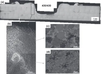
Optical micrographs of 430/430 joints are displayed in
Fig. 6. A semi-elliptically shaped structure of ferrite and
martensite is observed at the near-surface region of the TMAZ (see the region of indent A). The rapid cooling rate and high plastic deformation during the FSW process stimulates the transformation of coarse ferrite grains in the
BM to a fine duplex structure of ferrite and martensite in
TMAZ.17) This leads to a significant increase in hardness
(³330 HV) in the TMAZ region compared to the base
material (see Table 1). Additionally, high heat input and severe shear deformation of the welded materials results in dynamic rescrystallization and an increase in the fraction of
the low angle grain boundaries.18)In the region of indent B,
coarser equiaxed ferrite grains with chromium carbides form at the grain boundary (Fig. 6(c)). This results in a decrease
of hardness (³245 HV). The morphology change of the
chromium carbides from coarse leaf-like tofine spherical-like
in the microstructure is demonstrated in Figs. 6(c) and 6(d).
The fine chromium carbide particles segregate in the
indent D region, which cause a considerable increase in
hardness (³360 HV). However, the base material contains
coarser ferrite grains containing only a few chromium
carbides. As a result, it shows a lower hardness
Fig. 4 Details of Fig. 3(b): (a) optical microscopy image at higher resolution, (b) EBSD orientation map and (c) EBSD grain boundary map.
[image:4.595.104.493.71.287.2] [image:4.595.321.531.347.480.2](³181 HV). Previous work suggests that the fraction of low
angle grain boundaries in the stir zone (SZ) was significantly
increased as compared to that in the BM.18)This means that
the amount of recovery is affected by the operating temper-ature during FSW and therefore dynamic recrystallization
occurred not only in the SZ.18) It should be noted that the
hardness increase in the TMAZ is caused by both grain
refinement and angle boundary change. The low angle
boundary implies a recovery stage with sub-grain formation and rearrangement of dislocations. The different phases of the
430/430 joint have also been identified by XRD
measure-ment, as shown in Fig. 7. The XRD spectrum reflects the
formation of alpha ferrite and chromium carbides in the
430/430 joint, which correspond to the SEM observation.
Note that martensite is hardly detectable in XRD spectra as
its reflection peaks are close to alpha ferrite and also has a
low volume fraction.
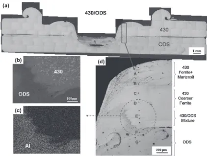
3.4 The 430/ODS joint
Figure 8 shows the macro- and microstructure of the dissimilar friction stir welded joints. The FSW tool was plunged on the 430 stainless steel to join with the ODS steel. On the top region of the joint, the indents A and B are visible and located in the TMAZ region. The microstructure consists
of a duplex structure of thefine ferrite and martensite with a
high hardness value of 301 HV. The increase in hardness also
corresponds to dynamic recrystallization and grain refinement
in this region. Indents C and D have a coarser equiaxed ferrite grain structure. No martensitic structure formation was
observed in that region. This leads to a significant decrease
in hardness (188 HV). Figure 8(b) shows the mixture region
of the 430/ODS joint. In the 430 stainless steel region, the
microstructure shows an equiaxed grain structure with distributed chromium carbides formed at grain boundaries, see the indent E (220 HV). EDX mapping was performed on
the mixture region of the 430/ODS joint. High levels of
aluminum in the ODS region can be apparently identified.
Therefore, the dissimilar interface between 430 steel and ODS alloy is clearly seen in the SEM image shown in Fig. 8(c). The grain size, grain boundary character, and grain
orientation of the 430/ODS mixture area were further
investigated by EBSD. Figure 9(a) shows a random grain orientation with a grain size of about 20 µm formed in the 430 stainless steel region. The grain size is slightly larger than in the region of the ODS steel. The angle boundary map,
Fig. 6 Optical microscopy image of the cross section of the 430/430 joint: (a) overview, (b) SEM image showing the indents AD row across the welding zones, and an enlarge SEM image of (c) the indent B and (d) indent C regions.
Fig. 7 XRD analysis of the 430/430 and 430/ODS joint.
[image:5.595.95.503.72.370.2] [image:5.595.48.290.431.563.2]Fig. 9(b), also indicates that the large fraction of the low angle boundary (gray line) was observed at the 430 stainless steel region. This represents predominantly the recovery stage with sub-grain structure. Contrary, the ODS steel in the FSW joints composed of mostly high angle grain boundaries which implies the formation of dynamic recrystallization. The initial elongated grains have been transferred to equiaxed grains due to nucleation of new grains and growth by motion of high angle grain boundaries. The different phases of the
430/ODS joint have also been identified by XRD. The XRD
spectrum indicates the formation of alpha ferrite, tungsten
and chromium carbide in the 430/ODS joint. Alpha-ferrite is
main phase in the 430/ODS joint and its grain structure
changes with the different welding zones, as shown in Fig. 8.
However, the chromium carbide, (Fe,Cr)7C3, was not visible
from SEM or OM images due to very small particle size. Additionally, it should be note that the presence of tungsten is due to the abrasion of the FSW tool during the welding process and merged with the joint material. A high
concentration of tungsten has also been confirmed by energy
dispersive X-ray (EDX) analysis.
4. Conclusions
The microstructural evolution in different joints of the ODS alloy and 430 stainless steel during FSW was examined. Three different zones in the joints could be
identified: the thermo-mechanically affected zone, the heat
affected zone and the base material. In the ODS/ODS joint,
Fig. 8 Optical microscopy image of the cross section of the 430/ODS joint: (a) overview, (b) the SEM image of the mixture area, (c) the EDS map for aluminum, (d) detail with Vickers indent row across the welding zones.
[image:6.595.86.508.67.386.2] [image:6.595.57.281.433.761.2]the elongated grains in the base material are dynamically
recrystallized to a fine-equiaxed grain structure with high
angle grain boundaries in the TMAZ. A further heat
treatment (1380°C for 1 h) of the HT-ODS/ODS joints
results in secondary recrystallization with a large grain structure (>200 µm). This results in a hardness decrease in the TMAZ compared to the base material. There is only a
slight decrease of hardness in the base material of about 5%
after annealing. It is evident that only recovery has taken
place in the ODS/ODS base materials with a sub-grain of
low angle grain boundary structures present in this stage. The
430/430 joint shows a fine duplex structure of ferrite and
martensite in the TMAZ. Dynamic recrystallization and grain
refinement were also observed in this region, but result in an
increase of hardness compared to the base 430 stainless steel material. These results can be attributed to the rapid cooling rate and high plastic deformation during the FSW process.
The 430/ODS joint displays a complicated microstructure
in the mixture region. The large fraction of the low angle grain boundary in the 430 stainless steel region proves that not only dynamic recrystallization but also recovery took place. The ODS steel is composed of mostly high angle grain boundaries. The initially elongated grains have been trans-ferred to equiaxed grains, implying the formation of dynamic recrystallization.
Acknowledgements
The authors would like to gratefully acknowledgefinancial
support from the National Science Council of Taiwan under the grant NSC 101-2911-I-214-501 and the Deutscher Akademischer Austauschdienst (DAAD) under the grant ID 54368608.
REFERENCES
1) C. L. Chen, A. Richter, R. Kögler and G. Talut:J. Nucl. Mater.412 (2011) 350358.
2) H. Kishimoto, K. Yutani, R. Kasada and O. Hashitomi:J. Nucl. Mater. 367370(2007) 179184.
3) T. Yamamoto, G. R. Odette, P. Miao, D. T. Hoelzer, J. Bentley, N. Hashimoto, H. Tanigawa and R. J. Kurtz: J. Nucl. Mater.367370 (2007) 399410.
4) G. R. Odette, M. J. Alinger and B. D. Wirth:Annu. Rev. Mater. Res.38 (2008) 471503.
5) L. L. Hsiung, M. J. Fluss and A. Kimura:Mater. Lett.64(2010) 1782 1785.
6) M. A. Pouchon, J. Chen, R. Ghislemi, J. Michler and W. Hoffelner:
Exp. Mech.50(2010) 7984.
7) R. L. Klueh, K. Ehrlich and F. Abe: J. Nucl. Mater.191194(1992) 116124.
8) N. Baluc, R. Schäublin, P. Spätig and M. Victoria: Nucl. Fusion44 (2004) 5661.
9) C. C. Hsieh and W. Wu:Met. Mater. Int.17(2011) 375381.
10) M. Ghosh, K. Kumar and R. S. Mishrab:Scr. Mater.63(2010) 851 854.
11) S. H. Park, Y. S. Sato, H. Kokawa, K. Okamoto, S. Hirano and M. Inagaki:Scr. Mater.49(2003) 11751180.
12) T. Saeid, A. Abdollah-zadeh, T. Shibayanagi, K. Ikeuchi and H. Assadi:
Mater. Sci. Eng. A527(2010) 64846488.
13) C. L. Chen, G. J. Tatlock and A. R. Jones:J. Alloy. Compd.504(2010) S460S466.
14) C. L. Chen, P. Wang and G. J. Tatlock:Mater. High Temp.26(2009) 299303.
15) C. L. Chen, G. J. Tatlock and A. R. Jones:Mater. Sci. Forum638642 (2010) 38333838.
16) Y. L. Chen, A. R. Jones and U. Miller:Metall. Mater. Trans. A 33 (2002) 27132718.
17) A. K. Lakshminarayanan and V. Balasubramanian:Mater. Design31 (2010) 45924600.
18) H. H. Cho, H. N. Han, S. T. Hong, J. H. Park, Y. J. Kwon, S. H. Kim and R. J. Steel:Mater. Sci. Eng. A528(2011) 28892894.