Interrupt Shearing Test for Evaluating Effect of Large Shear Deformation
on Evolution of Microstructure into Ultra
fi
ne Grains
Jun Yanagimoto
1, Sumio Sugiyama
1, Shuji Kawando
2,+and Akira Yanagida
3 1Institute of Industrial Science, The University of Tokyo, Tokyo 153-8505, Japan2Graduate School of Engineering, The University of Tokyo, Tokyo 153-8505, Japan
3Department of Mechanical Engineering, Tokyo Denki University, Tokyo 101-8457, Japan
A new physical simulation method for evaluating the effect of shear deformation on the evolution of a microstructure is proposed. This method utilizes a high-speed compression testing machine and is capable of simulating the formation offine grained steels in the transformation route. The outline of the proposed method, which is based on shearing and named the‘interrupt shearing test’, is presented. The result of the preliminary application of the newly proposed test at an elevated temperature is shown. It becomes clear that the large shear deformation reproduced by the proposed method is capable of producingfine grained steels with a grain size of around 2 µm surrounded by high angle grain boundaries (HAGBs), although controlled cooling immediately after plastic deformation to accelerate transformation intofiner grains is not applied in the present test. [doi:10.2320/matertrans.MD201119]
(Received July 28, 2011; Accepted September 12, 2011; Published November 2, 2011)
Keywords: interrupt shearing test, physical simulation, severe shear deformation, ultrafine grained steel, niobium microalloyed steel, accerelated transformation, microstructure analysis
1. Introduction
There are strong social demands on lightweight con-structions, such as lightweight vehicles and efficient heat exchangers, to realize the efficient use of energy. High-strength structural metals with high specific tensile strengths are indispensable for realizing the above lightweight con-structions, and the future environmentally conscious society necessitates these metals with fewer alloying elements. One promising method that meets the above social demands is the use of a metal with an ultrafine grained structure, such as a bulk nanostructured metal. Such a metal should have sufficient elongation as well as sufficient weldability, because it will be part of a lightweight construction after metal forming, such as sheet metal forming, and cold forging and welding.
A marked number of investigations on the formation of a bulk nanostructured metal by using a severe plastic deformation (SPD) process have been performed,15) and most of them use nonferrous alloys with diversified chemical compositions and various alloying elements. At the same time, steel still occupies the largest share as a structure metal, and this situation will continue for the time being. In fact, aiming at producing ultrafine grained steels, several inves-tigations on the SPD of steel have been performed over the past decade.68) There are two process routes that produce ultrafine grained ferritic steels, namely, ferrite recrystalliza-tion and transformarecrystalliza-tion routes, as is shown in Fig. 1.9)As for thefirst recrystallization route, warm shape rolling and other SPD processes are utilized, and ultrafine grained steels with a grain size of 1 µm are successfully generated.1013)A smaller number of investigations are performed for the transforma-tion route, but a high-speed controlled rolling or multistage compression process is used to generate ultrafine grained plain carbon steels with a grain size of around 1 µm.1416)The
first route is promising for obtainingfiner grains because the
grain growth rate is lower at a lower temperature, but, as is usual in high strength metals, ultrafine grains that include many dislocations may deteriorate formability. Grain refi ne-ment thorough accelerated transformation from deformed austenite is promising for the formation of fine-grained steels.17) However, the formation of ultrafine grains by the transformation route is more difficult owing to the larger driving force for the change in microstructure in the austenite state at an elevated temperature. Thus, rather few inves-tigations are performed to generate nanostructured steels by the SPD process in the transformation route.11,18) To determine the process conditions for the formation of nanostructured steels in the transformation route, detailed investigations by physical simulation and numerical analysis will be required.
At present, hot compression test is widely used to reproduce the evolution of microstructure in hot forming process. Compressive deformation is the accumulation of shear deformation in a macroscopic viewpoint as is explained by G. I. Taylor19) and, furthermore, the effect of shear deformation on grain refinement is attracting more attention but is not still sufficiently clarified. Torsion test is capable of validating the effect of shear deformation to microstructure evolution, but requires a special testing machine and strain rate is limited.20) A new physical simulation method for
Austenite
SPD
Cooling
UFG Ferrite Ferrite
SPD
UFG Ferrite
Transformation route
Ferrite recrystallization route
Cooling
Fig. 1 Two routes of grain refinement of ferritic steels.
[image:1.595.336.515.334.440.2]evaluating the effect of shear deformation on the evolution of a microstructure is proposed. This method utilizes a high-speed compression testing machine and is capable of simulating the formation of fine grained steels in the transformation route. As the proposed test utilizes the high-speed compression testing machine, controlled shear defor-mation with high strain rate can be easily imposed on the specimen. The outline of the proposed method, which is based on shearing and named the‘interrupt shearing test’, is presented in this paper. The result of the preliminary application of the newly proposed test at an elevated temperature reveals that a large shear deformation results in fine grained steels with a grain size of around 2 µm surrounded by high-angle grain boundaries (HAGBs) whose misorientation angle exceeds 15 degree, even under air cooling conditions after plastic deformation.
2. Experimental Procedure
2.1 Construction of interrupt shearing test
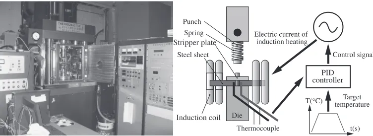
The high-speed hot forming simulator14) used in the physical simulation is shown in Fig. 2. This equipment is capable of simulating high-speed multistage deformations, such as tandem hot strip rolling, with the highest ram speed of 4000 mm·s¹1and the minimum interpass time of 0.3 s. If the specimen height is 12 mm, which is the standard size of the specimen for compression by the hot forming simulator, the maximum strain rate exceeds 300 s¹1, which covers the deformation rate range in high-speed tandem hot strip rolling. The controlling system for temperature is also shown in Fig. 2. By comparing the target temperature history and the actual one measured by a thermocouple welded to a controlling point of the steel sheet, and controlling the electric current of the induction heating unit by the PID algorithm, the temperature of the controlling point of the steel sheet, where the thermocouple is welded, is expected to follow the target temperature history.
Aiming at imposing a large amount of shear deformation on a steel sheet, the new physical simulation method, that is, the interrupt shearing test, has been developed on the basis of a shearing process, by which a large amount of shear deformation can be imposed on the steel specimen, as is shown in Fig. 3. To realize the shear deformation inside the hot forming simulator shown in Fig. 3, an experimental setup of the punch and die is newly designed and installed in the
experimental chamber of the hot forming simulator, as is shown in Fig. 4. This method is based on shearing, but deformation is terminated before breaking the steel. By interrupting shear deformation with the predetermined stroke of the punch and the gap between the punch and the die, the target shear deformation is applied, and shear bands and dislocations could be introduced into the metal as steel sheets at an elevated temperature. The subsequent controlled cooling is expected to realize the accelerated transformation into fine grained ferrite-pearlite structures because of the elevated driving force of transformation and increases in the numbers of nucleation sites and their activities for trans-formation.
2.2 Experimental conditions
The interrupt shearing test in a hole section is conducted in this investigation. As is shown in Fig. 4, the punch diameter is 8 mm and the die hole diameter is 9 mm. Thus, the gap between the die and the punch ¦c in Fig. 3, which is a representative parameter in the interrupt shearing test, is 0.5 mm. The sheet thicknesshandfinal punch stroke¦hare 3 mm and 2 mm, respectively; thus, the nominal shear strain
£, defined by,
£¼hc; ð1Þ
under these physical simulation conditions is 4, which is in the severe plastic deformation (SPD) range. The sheet length and width are 18 mm and 50 mm, respectively. The temperature history of a controlling point and stroke diagram Punch
Die Steel sheet
Induction coil
Thermocouple
PID controller Electric current of
induction heating
t(s) T(°C) Target
temperature Spring
Control signal Stripper plate
Fig. 2 Schematic view of high-speed multistage hot forming simulator and its controlling system for temperature.
Shear deformation zone Material flow
Δc
Δh
[image:2.595.112.488.70.207.2] [image:2.595.325.528.251.378.2]versus time are summarized in Fig. 5. Slow forming speed as 1 mm·s¹1, that corresponds to nominal shear strain rate of 2 s¹1, is chosen as standard condition of this experi-ments. The controlling point of temperature within specimen will be explained in the followings in detail. A Nb microalloyed steel (0.16%C1.41%Mn0.030%Nb) is used in the experiment aiming at utilizing the pinning effect to obtain austenite with a high accumulated dislocation density before transformation. The Ae3 temperature of this steel is about 820°C.
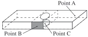
One of the key issues of this physical simulation is where to locate a controlling point of the temperature history. The most desirable point is where a large shear deformation occurs, as is shown in Fig. 3. However, as this zone exhibits a severe shear deformation between the die and the punch, it is impossible to ensure the reproducibility of temperature data because of the difficulties in welding and keeping a thermocouple there and drawing out an electric wire without breakage. Thus, two points are selected to determine the best place to locate a controlling point, as is shown in Fig. 6. Point A is the edge of the length of the steel sheet, which is the easiest point to measure temperature, but is far from the shear deformation zone. After validating the temperature data
from controlling point A, point B is tested to determine whether this point could be used as a controlling point of temperature in a hot forming simulator.
3. Experimental Results
3.1 Measurement of temperature distribution
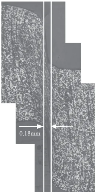
Point A in Fig. 6 is selected as a controlling point of temperature, and the interrupt shearing test is conducted. The temperature of point A during the interrupt shearing test is 800°C. The initial microstructure of the shear deformation zone and its microstructure after the interrupt shearing test are compared in Figs. 7 and 8. Here, as is shown in Fig. 7, the width of severe shear deformation zone is 0.18 mm, which is about 6%of the initial thickness of specimen. Nital etching is used to expose the grain boundary. In this figure, a severely elongated structure that proves the occurrence of the severe shear deformation could be seen; however, no trace of transformation could be observed in this region. As the controlling temperature of controlling point A is 800°C, it is easy to infer that no inverse transformation into austenite grains occurs in the shear deformation zone. In fact, the measured temperature of point C in Fig. 6, which is located only on the opposite side of the sheet from the punch, is about 60°C lower than that of point A. From this measure-ment, at least, the temperature of controlling point A should be the Ae3 temperature plus 60°C to obtain an austenite microstructure in a shear deformation zone.
Fig. 4 Experimental setup of newly proposed interrupt shearing test.
Holding(900°C) Air cooling Heating(10°C/s)
10s 1s
40
-2
Stroke[mm]
0
90s 4s 2s
4s T
emperature[
°
C]
900
20 Time[s] Sheet surface
Forming (1mm/s) Down (10mm/s) Up
(10mm/s) Up
Fig. 5 Temperature history of controlling point and stroke diagramversus
time.
Point C Point B
Point A
[image:3.595.104.491.69.291.2] [image:3.595.64.277.336.454.2] [image:3.595.349.503.337.402.2]3.2 Fine grained structures after hot interrupt shearing test
From the above measurements, it was clarified that the temperature of a controlling point should exceed 820°C plus 60°C. Thus, the target temperature is selected as 900°C and the temperature of point B, which is closer to the shear deformation zone, is selected as a controlling point. The macroscopic view of the steel sheet after the interrupt shearing test is shown in Fig. 9. The boundary misorientation map of the shear deformation zone and that of an adjacent zone with a small plastic deformation are compared in Fig. 10. Scope of field in EBSD (electron backscatter diffraction) analysis is 200 µm©200 µm and step size is
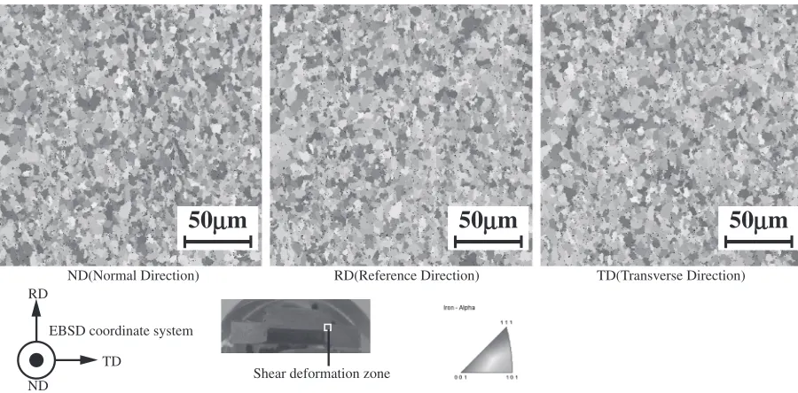
0.5 µm. IPF in Fig. 11 shows that typical transformed microstructure with random orientation is obtained after interrupt shearing test. It is clear that shear deformation promotes grain refinement, and grains are equiaxed during transformation. Also, these boundary misorientation maps show that almost all grain boundaries are high-angle ones. The linear intercept measurement of the structure shows that the grain size of the shear deformation zone lies between 1.8 µm and 2.7 µm. As is shown in Fig. 5, a fine grained microstructure composed of HAGBs is obtained, even though no accelerated cooling is applied to the steel sheet after the interrupt shearing test. This result may indicate that a steel structure with several hundred nanometer ferrite-pearlite-bainite grains could be obtained after the optimization of the cooling conditions immediately after shear deformation, which is reproduced by the newly developed physical simulation method. This is a challenging target for the steel sheets, and, in order to reach this goal, we should seek the best combination of process parameters, such as plastic deformation and transient change in temperature,21,22) that could be obtained by the physical simulation method proposed in this paper.
4. Conclusion
A new physical simulation method for evaluating the effect of shear deformation on the formation of a nanostructured metal is proposed in this paper. As the proposed method utilizes a high-speed hot forming simulator, microstructure evolution at an elevated temperature could be quantitatively examined, including the grain refinement of steels into fine grained onesviatransformation. The preliminary application of the proposed method to niobium steel shows that a microstructure with an average grain size of 2 µm and HAGBs is generated in the shear deformation zone, even
(a) (b)
Fig. 8 Initial microstructure (left) and microstructure of shear deformation zone after interrupt shearing test.
[image:4.595.89.249.245.565.2] [image:4.595.342.511.513.565.2] [image:4.595.105.497.612.770.2]though no controlled cooling to accelerate transformation into fine grains is applied in the test. Further investigations are required to obtain nanostructured steel with a grain size of several hundred nanometers by the newly developed physical simulation method.
Acknowledgement
This study was financially supported by a Grant-in-Aid for Scientific Research on Innovative Area, “Bulk Nanostructured Metals”, through MEXT, Japan (contract No. 22102005).
REFERENCES
1) A. Azushima, R. Kopp, A. Korhonen, D. Y. Yang, F. Micari, G. D. Lahoti, P. Groche, J. Yanagimoto, N. Tsuji, A. Rosochowski and A. Yanagida:CIRP Ann. Manuf. Technol.57(2008) 716735.
2) R. Z. Valiev, R. K. Islamgaliev and I. V. Alexandrov:Prog. Mater. Sci.
45(2000) 103189.
3) For example, R. Z. Valiev:Mater. Sci. Forum503504(2006) 310.
4) B. Cherukuri, T. S. Nedkova and R. Srinivasan: Mater. Sci. Eng. A
410411(2005) 394397.
5) T. C. Lowe:JOM58(2006) 2832.
6) N. Tsuji, Y. Saito, S. H. Lee and Y. Minamino:Adv. Eng. Mater.5
(2003) 338344.
7) K. T. Park, S. Y. Han, D. H. Shin, Y. K. Lee, K. J. Lee and K. S. Lee:
Reference zone without plastic deformation
Shear deformation zone
Shear deformation zone
Reference zone
without plastic deformation
15° 5° 2°
180° 15°
5° Boundaries: Rotation Angle
Min Max
50
μ
m
[image:5.595.104.490.68.336.2]50
μ
m
Fig. 10 Comparison of boundary misorientation map of shear deformation zone and that of adjacent zone without plastic deformation.
Shear deformation zone
50
μ
m
50
μ
m
50
μ
m
ND(Normal Direction) RD(Reference Direction) TD(Transverse Direction) RD
TD
EBSD coordinate system
ND
[image:5.595.72.522.379.601.2]ISIJ Int.44(2004) 10571062.
8) A. Yanagida, K. Joko and A. Azushima:J. Mater. Process. Tech.201
(2008) 390394.
9) S. Torizuka: Bull. Iron Steel Inst. Jpn.10(2005) 188195.
10) Y. Hagiwara, M. Niikura, M. Shimotomai, Y. Abe and Y. Shirota: J. JSTP42(2001) 402407.
11) S. Torizuka, K. Nagai and A. Sato: J. JSTP42(2001) 287292. 12) T. Inoue, S. Torizuka and K. Nagai: Tetsu-to-Hagané86(2000) 793
800.
13) S. Torizuka, T. Inoue and K. Nagai: Tetsu-to-Hagané86(2000) 801 806.
14) J. Yanagimoto, Y. Kobayashi and A. Yanagida: Steel Res. Int. 78
(2007) 812817.
15) M. Etou, S. Fukushima, T. Sasaki, Y. Haraguchi, K. Miyata, M. Wakita,
T. Tomida, N. Imai, M. Yoshida and Y. Okada:ISIJ Int.48(2008) 11421147.
16) T. Tomida, N. Imai, K. Miyata, S. Fukushima, M. Yoshida, M. Wakita, M. Etou, T. Sasaki, Y. Haraguchi and Y. Okada:ISIJ Int.48(2008) 11481157.
17) I. Tamura:Trans. ISIJ.27(1987) 763779.
18) T. Yamashita, S. Torizuka and K. Nagai:ISIJ Int.43(2003) 18331841.
19) H. Takahashi: Polycrystal Plasticity, (Corona Publishing Co., 1999) pp. 6869.
20) H. Beladi, G. L. Kelly, A. Shokouhi and P. D. Hodgeson:Mater. Sci. Eng. A367(2004) 152161.
21) Y. Adachi, T. Tomida and S. Hinotani: Tetsu-to-Hagané85(1999) 620 627.