Effect of High-Density Electric Current on the Microstructure
and Fatigue Crack Initiation of Stainless Steel
Yongpeng Tang
+, Atsushi Hosoi, Yuichi Iwase
+and Yang Ju
Department of Mechanical Science and Engineering, Nagoya University, Nagoya 464-8603, Japan
To investigate the effect of high-density electric current on the delay of fatigue crack initiation, the dislocation structures before and after the application of electric current were investigated by transmission electron microscopy. Dislocation density was quantitatively characterized before and after the application of electric current to further understand the mechanics of the healing effect. Atomic force microscope results showed that the slips disappeared locally and the slip height decreased on the surface of the specimens. Furthermore, the delaying effect of the crack initiation due to the application of electric current was evaluated by the fatigue crack-initiation model in which the accumulation of the dislocation density was considered. [doi:10.2320/matertrans.M2013198]
(Received May 27, 2013; Accepted August 13, 2013; Published October 4, 2013)
Keywords: fatigue, crack initiation, electric current, slip bands, dislocation
1. Introduction
It is reported that at least half of all the mechanical failures are due to fatigue.1) Therefore, it is essential to prevent fatigue fractures to improve long-term durability and reliability of structures. Although the application of electric current to improve the fatigue life has been proposed,2,3) many researchers have focused on fatigue crack healing.4,5)
However, studies regarding the effect of current application on the delay of fatigue crack growth are limited. Recently, the effect of electric current on the dislocation structure in fatigue damage has been reported. Konovalov et al.6,7) found that
the dislocation substructures changed by the electropulsing treatment. They concluded that the change of dislocation substructures was the responsible for the improvement of the fatigue lifetime. The effect of high density electropulsing on decreasing the dislocation density also has been observed.8) Furthermore, it has been reported that the decreases of slip bands space and width due to the applied electric current are a potential way to prolong the fatigue crack initiation.9,10) However, the quantitative evaluation of the effect of the applied electric current on fatigue crack initiation has been limited to a few studies until now. During the fatigue loading process, the primary emphasis is on the fact that the fatigue crack initiation is caused by the accumulation of micro-defects, such as dislocations1113)in the material. To delay the
fatigue crack initiation, it is necessary to investigate the effect of the applied electric current on the damaged microstructure of the material.
The aim of this study is to elucidate the role of delaying fatigue crack initiation with the application of electric current, from a viewpoint of its physical mechanism. On the surface of the specimens, the height of the slip bands was quantitatively measured by atomic force microscope (AFM). In the microstructure of the material, the dislocation density was quantitatively evaluated by transmission electron microscopy (TEM) and the section line method. Based on the combination of the experiments and the fatigue crack initiation model, the relationship between the change of
dislocation structure due to the application of electric current and the delay of fatigue crack initiation was investigated.
2. Experimental Approach
2.1 Specimen
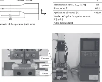
Austenite stainless steel SUS316 was used as the experimental material. The chemical compositions and mechanical properties of SUS316 are presented in Tables 1 and 2, respectively. Metallographic observations showed that the average linear intercept grain size was approximately 75 µm in the initial state as shown in Fig. 1. A notch was introduced in the dumbbell-shaped specimen at the center of one of the side edges as shown in Fig. 2. The length and the root radius of the notch were 2 and 0.15 mm, respectively. The specimens were subjected to a stress relief annealing treatment at 1173 K for 10 min to remove the residual stresses caused by the machining process. After annealing, the surface of the specimen was polished using emery papers with grain numbers from #400 to #2000. Finally, the specimen was polished to a mirrorfinish by buffing with alumina powder with a grain diameter of 0.05 µm.
2.2 Fatigue test and application of electric current
[image:1.595.304.551.313.343.2]Tensile fatigue tests under controlled load conditions with a hydraulic-driven testing machine were carried out at room temperature. The tests were conducted at a stress ratio of
Table 1 Chemical compositions of the stainless steel SUS316 (mass%).
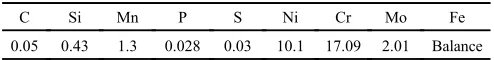
C Si Mn P S Ni Cr Mo Fe
0.05 0.43 1.3 0.028 0.03 10.1 17.09 2.01 Balance
Table 2 Mechanical properties of SUS316.
Yield stress [MPa] Tensile strength [MPa] Elongation [%] Reduction of area [%]
Young’s modulus [GPa]
Poisson’s ratio
Hardness [HBW]
300 573 47 76 197 0.29 161
+Graduate Student, Nagoya University
[image:1.595.305.549.385.433.2]R=0.05 and a frequency of f=10 Hz. A high-density electric current was applied after the fatigue tests with different cycles using a transistor-type power source. Chromium copper with a 5 mm diameter was used as the electrodes. The two electrodes were connected to the side of the specimen, straddling the notch as shown in Fig. 3. An electric current of 3 kA with a pulse duration of 0.5 ms was applied to the specimen.
2.3 Evaluation of the healing effect
The effect of the high-density electric current on fatigue crack initiation was investigated under the test condition of maximum net stress of ·max=115 MPa. Fatigue tests were carried out under the three types of conditions as shown in Table 3, and under each condition, four specimens were used. In the present study, the fatigue crack initiation was defined
as the number of fatigue cycles required for the crack length to reach 25 µm. The process of microcrack initiation was monitored by in-situ observation using optical microscopy (OM).
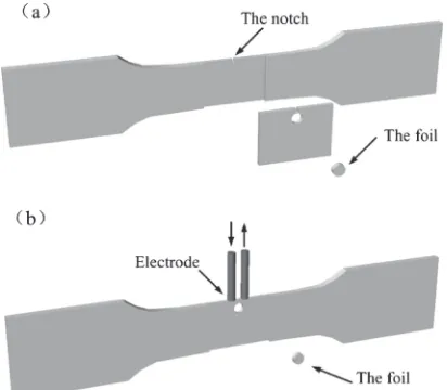
To observe the dislocation structure using TEM, thin foils with a 3 mm diameter were cut from the same position in the vicinity of the notch tip before and after the application of electric current as shown in Fig. 4. The surface of the thin foil was mechanically polished to 100 µm thickness, and then electropolished with a double jet apparatus. Because the sample surface layers affected by the mechanical grinding were fully removed by subsequent electropolishing, this preparation procedure for the standard TEM sample can effectively preserve the original material structure.
The dislocation density has been measured by the section line method with the correlation for dislocation invisibility.14,15)Scanning lines were drawn horizontally and
vertically over the observed images, and the number of intersection points of these lines with the dislocations was counted. The dislocation density can be expressed as the ratio of the number of points, N, to the product of the total length of the lines,Land the foil thickness,t:
µ¼ N
Lt ð1Þ
The accuracy of the dislocation density measurements depends on the precise measurement of the foil thickness, which is determined by a convergent beam electron diffraction technique.16) Kelly et al.17) showed that the
thickness can be measured by the convergent beam electron diffraction technique with an accuracy of 5%. The dislocation
Fig. 1 Optical micrograph of the microstructure in the original state.
Fig. 2 Schematic of the specimen (unit: mm).
[image:2.595.61.277.283.447.2]Fig. 3 Specimen and electrodes used for applying the electric current.
Table 3 Test conditions of fatigue and applied current.
Condition A
Condition B
Condition C
Maximum net stress,·max[MPa] 115 115 115
Stress ratio,R 0.05 0.05 0.05
Application of current [A] without 3000 3000
Number of cycles for applied current,
N[cycle] 1.0©10
5 2.0©105
[image:2.595.301.552.483.583.2] [image:2.595.54.281.494.569.2] [image:2.595.130.467.500.771.2]distribution highly influences the qualitative estimation of the dislocation density. In the present study, ten areas in one specimen were measured to determine the dislocation density under each condition. Similar dislocation distributions were observed in the specimens under each condition.
3. Results
3.1 Fatigue crack initiation
Figure 5 shows the fatigue life based on the crack initiation at a maximum net stress of·max=115 MPa. When the electric current was not applied, the crack initiation was observed at an average of 2.34©105 cycles as shown in Table 4. It was found that the fatigue crack initiation was extended after the application of electric current. When the electric current was applied at 2.0©105 cycles, the crack initiation was observed at an average of 2.82©105 cycles with a maximum of 3.2©105cycles. The number of cycles increased to 20.5% on average due to the healing effect. However, when the electric current was applied at 1.0©105
cycles, the crack initiation occurred at an average of 2.47© 105 cycles. The increased number of cycles was limited to
5.3%on average. The results indicate that the application of
electric current delays the fatigue crack initiation, and the delaying effect was different depending on the timing of the application of electric current.
3.2 Observations of dislocation
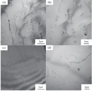
Figures 68 show the TEM images of the typical dislocation structures. Only a few dislocations were observed in the original material, as shown in Figs. 6(a) and 6(b). The average dislocation density of the original state was 1.38©109m¹2. With the increase of cyclic loading, local
[image:3.595.67.273.70.250.2]high-density dislocation structures, such as dislocation lines and pile-ups, were formed as shown in Figs. 7(a), 7(b) and Figs. 8(a), 8(b). The average dislocation density at 1.0©105 Fig. 5 Relationship between the maximum net stress and the number of cycles of fatigue crack initiation, with and without the electric current.
Table 4 Experimental and calculated average number of cycles for crack initiation.
Condition A Condition B Condition C
Experimental average number of
cycles for initiation,N[cycle] 2.34©10
5 2.47©105 2.82©104
Calculated average number of
cycles for initiation,N[cycle] 2.45©10
5 3.29©104 Fig. 4 Preparation for TEM sample (a) before and (b) after the application
of electric current.
[image:3.595.315.537.70.228.2] [image:3.595.138.461.308.471.2] [image:3.595.303.550.539.603.2]Fig. 8 Typical TEM images of dislocation structure: (a) low magnification after 2.0©105cycles; (b) high magnification after 2.0©105 cycles; (c) low magnification after the application of electric current; (d) high magnification after the application of electric current. Fig. 7 Typical TEM images of the dislocation structure: (a) low magnification after 1.0©105 cycles; (b) high magnification after
[image:4.595.135.462.68.394.2] [image:4.595.135.460.441.763.2]cycles was 5.51©1012m¹2. The dislocation density
in-creased with an increase of loading cycles as shown in Fig. 8. A large amount of the dislocation slips were observed at 2.0©105 cycles. The average dislocation density increased
up to 1.08©1013m¹2.
To investigate the effect of the current application on the dislocations, the dislocation structure was observed after the application of electric current as shown in Figs. 7(c), 7(d) and Figs. 8(c), 8(d). It was found that the dislocation pile-ups disappeared and the dislocation density greatly decreased. Figure 9 shows the evolution of the dislocation density before and after the current application. It is noted that the average dislocation density decreased to 4.67©1012m¹2
when the electric current was applied at 2.0©105 cycles.
When the electric current was applied at 1.0©105 cycles,
average dislocation density decreased to 4.0©1012m¹2.
These results show that the delaying effect of the electric
current on the fatigue crack initiation is related to the decrease of the dislocation density.
3.3 Observations of slips
Figure 10 shows the topography of the specimen surface observed by AFM. The characteristics of the slips at the same site were compared before and after the application of electric current. It was observed that the height of the slip bands decreased after the application of electric current. The slip bands A and B disappeared after the application of electric current. Figure 11 shows the characteristics of the surface relief profiles on the three different lines of S1, S2 and S3 as shown in Fig. 10(a). It was found that the height of the slips decreased. It is noted that the slips are healed easily when the height of the slip is smaller than 10 nm. These results indicate that the slips were homogenized as a result of the local disappearance of the slips and the decrease of the slip height.
4. Evaluation of Healing Effect
4.1 Fatigue crack initiation model
To investigate the delaying effect of electric current on crack initiation, the dislocation structure is essential to relate the mechanism of crack initiation. Fatigue is characterized by a series of forward and reverse loading. The primary em-phasis is the relationship between the fatigue crack initiation and the microstructure of the material.1822)According to the
classical dislocation dipole model proposed by Tanaka and Mura,2326)the dislocations nucleate and slip in the slip bands
under forward and reverse loading. Irreversible slip leads to dislocation motion on a slip plane and dislocation pile-ups. The dislocation density increases with the accumulation of
[image:5.595.61.277.296.438.2]Fig. 9 Dislocation density before and after the application of electric current.
[image:5.595.165.434.489.762.2]the dislocation ups. Representing the dislocation pile-ups in terms of continuum dislocations, Tanaka and Mura23)
showed the dislocation accumulation for the case of double piles-up. After cyclic loading ofncycles, the total density of dislocation is given by:
D¼ð1vÞ
G ½ð¸1kÞ þnð¸2kÞ ð2Þ
where,
¸¼¸1¸2; ð3Þ ¸1is the maximum shear stress and ¸2is the minimum shear stress in one cycle. k is the frictional stress,G is the shear modulus, v is the Poisson’s ratio and n is the number of fatigue cycles. The stored strain energy of dislocation can be expressed using the function of the dislocation density by23)
W¼
Z a
a ¸Ddx
2 ð4Þ
where 2a is the grain size. When the strain energy due to the dislocations accumulated at the plastic zone reaches a critical value, the microcracks at notch tip occurs. Therefore, the increase of the dislocation density is represented by the accumulation of the strain energy stored in the dislocation. When the dislocation density reaches a critical value,Df, the
number of fatigue cycles leading to the crack initiation is obtained by equating the stored energy in the dislocation dipoles to the specific fracture energy (Ws).
4.2 Predicating the delaying effect of current application on crack initiation
According to the theories of crack initiation mentioned earlier, there are criteria for crack initiation that are based on the achievement of some critical damage accumulation.26)
From eqs. (2) and (4), we can obtain the relationship between the dislocation density,Dand the fatigue cycles,n, as shown in Fig. 9. Consequently, the damage parameter, P, can be readily evaluated in terms of the variation of the dislocation density.
P ¼DmDi DfDi
ð5Þ
where, Dm and Diare the dislocation density of a damaged
material and a non-damaged material, respectively. According to the experimental results that the fatigue crack initiation occurs at 2.34©105 cycles, a critical value of the
dislocation density, Df=1.03©1013, was calculated using
[image:6.595.137.459.65.308.2]the eq. (2). Hence, the delaying effect of the current application on the crack initiation was predicted by the decrease of the damage accumulation as shown in Fig. 12.
Fig. 11 Profiles of the surface height in three different lines in Figs. 10(a) and 10(b): (a) before and (b) after the application of electric current for line S1; (c) before and (d) after the application of electric current for line S2; (e) before and (f ) after the application of electric current for line S3.
[image:6.595.317.536.370.536.2]Comparison of the model calculation and the experimental data are presented in Table 4. The damage parameter,
P=0.95, was obtained at 2.0©105 cycles using eq. (5)
and decreased to P=0.45 after the application of electric current. Hence, the number of cycles for the crack initiation was predicted at 3.24©105 cycles using eq. (2). Although the average crack initiation cycles are less than the predicted cycles, the predicted number of cycles is within the scatter of the experimental results. However, when the electric current was applied at 1.0©105 cycles, the damage parameter, P, decreased from 0.53 to 0.38. The number of cycles for crack initiation was predicted at 2.45©105 cycles. It was found
that the delaying effect of the current application depends on the healing effect on the fatigue damage. Therefore, the delaying effect due to the application of electric current corresponds to the fatigue crack initiation model of Tanaka and Mura. After applying the electric current, the decrease of the dislocation density can be used to predict the delay of the crack initiation.
5. Discussion
5.1 Effect of electric current on dislocation annihilation
Upon unloading, the total strain energy of dislocation is minimized in the system. Hence, the dislocations with opposite signs are activated to reverse slip on an adjacent plane.24) Annihilation also occurs when two dislocations of
opposite sign from different dislocation pairs approach each other. The movement and annihilation of the dislocations is an important mechanism of recovery. The annihilation of the dislocations reduces the dislocation density.
When the electric current was applied upon unloading, it can exert a drag on the dislocations as the electrons collide with the atoms. The force due to the drag is called the electron wind force and is proportional to the current density.27) Williams et al.28) experimentally verified the electron wind force exerted on the motion of nanoscale structures. The structures can be moved by the electron wind force back and forth when the direction of the current is changed. Therefore, the electron wind force may be one of the important reasons for the annihilation of dislocation. The retardation of the crack initiation affected by the reverse process of the dislocation in inert environments and at low temperatures has been demonstrated by Sriram et al.29)and
Kwon et al.,30) respectively. The increased reverse of
dislocation has been proved to extend the number of cycles for crack initiation. On the basis of the experimental results, the reverse of dislocation leads to a uniform distribution and a low density of the dislocations. Thus, after the application of electric current, the dislocation density decreased due to the annihilation of the dislocation dipoles. On the other hand, the application of high-density electric current causes a high-speed heating. The increase in the temperature was approximately 230°C in this experiment. It is thought that the joule heating is a side effect. Zhou et al.31) compared the dislocation densities under the treatments of electropulsing and annealing. It was found that the dislocation density in the electropulsed treatment is lower than that in the annealed treatment. Moreover, it was suggested that the effect of heating on the mobility of the dislocation is limited.
5.2 Effect of applied electric current on healing of slip bands
As shown in Figs. 10 and 11, the step height of the slip bands formed during the cyclic loading was decreased after the electric current was applied. The mechanism for the healing of slip bands has not been clarified yet, but the reverse slip could occur due to the dislocation motion excited by electron wind force or the thermal compressive stress induced by the application of electric current. As was described in section 5.1, the electric current can exert a drag force on the dislocations as the electrons collide with the atoms when the electric current was applied. The dislocation motion was activated due to the electron wind force. In the micro-structures, the dislocation motion can create the possibility of the reverse slip. In addition, the joule heating, because of the temperature rise upon the application of electric current, was in duration of 0.5 micro seconds. Therefore, the application of electric current is a high-speed heating process. When the rate of temperature rise is greatly higher than that of thermal expansion, the thermal compressive stress occurred in high-speed heating.32)The thermal compressive stress could activate the reverse slip around the notch.
6. Conclusions
The delaying of the fatigue crack initiation was realized by the application of electric current. The disappearance of the slip bands locally and the decrease of slip height were observed after the application of electric current. In addition, the dislocation density decreased after the application of electric current. The delaying effect was shown by the fatigue crack initiation models that considered the effects of the dislocation density.
Acknowledgement
This work was supported by the Japan Society for the Promotion of Science under Grant-in-Aid for Young Scientists (A) 23686021.
REFERENCES
1) R. I. Stephens, A. Fatemi, R. R. Stephens and H. O. Fuchs:Metal Fatigue in Engineering, (Wiley-IEEE, 2000).
2) G. V. Karpenko, O. A. Kuzin, V. I. Tkachev and V. P. Rudenko: Sov. Phys. Dokl.21(1976) 159160.
3) H. Conrad, J. White, W. D. Cao, X. P. Lu and A. F. Sprecher:Mater. Sci. Eng. A145(1991) 112.
4) A. Hosoi, T. Nagohama and Y. Ju:Mater. Sci. Eng. A533(2012) 38 42.
5) H. Q. Lin, Y. G. Zhao, Z. M. Gao and L. G. Han:Mater. Sci. Eng. A 478(2008) 93100.
6) S. V. Konovalov, A. A. Atroshkina, Y. F. Ivanov and V. E. Gromov: Mater. Sci. Eng. A527(2010) 30403043.
7) O. V. Sosnin, A. V. Gromova, Y. F. Ivanov, S. V. Konovalov, V. E. Gromov and E. V. Kozlov:Int. J. Fatigue27(2005) 11861191. 8) G. H. He, B. Q. Wang, X. N. Guo, F. Yang, J. D. Guo and B. L. Zhou:
Mater. Sci. Eng. A292(2000) 183188.
9) S. H. Xiao, Y. Z. Zhou, J. D. Guo, S. D. Wu, G. Yao, S. Li, G. H. He and B. L. Zhou:Mater. Sci. Eng. A332(2002) 351355.
10) W. D. Cao and H. Conrad:Fatigue Fract. Mater. Struct.15(1992) 573 583.
12) J. R. Hancock and J. C. Grosskreutz:Acta Mater.17(1969) 7797. 13) C. Laird, P. Charsley and H. Mughrabi:Mater. Sci. Eng. A81(1986)
433450.
14) D. M. Norfleet, D. M. Dimiduk, S. J. Polasik, M. D. Uchic and M. J. Mills:Acta Mater.56(2008) 29883001.
15) M. S. Pham, C. Solenthaler, K. G. Janssens and S. R. Holdsworth: Mater. Sci. Eng. A528(2011) 32613269.
16) D. B. Williams and C. B. Carter:Transmission Electron Microscopy, (Plenum Press, 1996).
17) P. M. Kelly, A. Jostsons, R. G. Blake and J. G. Napier:Phys. Status Solidi A31(1975) 771780.
18) C. Gaudin and X. Feaugas:Acta Mater.52(2004) 30973110. 19) O. B. Pedersen:Acta Mater.38(1990) 12211239.
20) X. Feaugas:Acta Mater.47(1999) 36173632.
21) M. D. Sangid, H. J. Maier and H. Sehitoglu:Acta Mater.59(2011) 328341.
22) M. D. Sangid: Int. J. Fatigue (2012) DOI:10.1016/j.ijfatigue.2012. 10.009.
23) K. Tanaka and T. Mura:J. Appl. Mech.48(1981) 97103. 24) T. Mura and Y. Nakasone:J. Appl. Mech.57(1990) 16.
25) G. Venkataraman, Y. W. Chung and T. Mura:Acta Metall. Mater.39 (1991) 26212629.
26) G. Venkataraman, Y. W. Chung and T. Mura:Acta Metall. Mater.39 (1991) 26312638.
27) A. F. Sprecher, S. L. Mannan and H. Conrad:Acta Metall. Mater.34 (1986) 11451162.
28) C. Tao, W. G. Cullen and E. D. Williams:Science328(2010) 736 740.
29) T. S. Sriram, M. E. Fine and Y. W. Chung:Scr. Metall.24(1990) 279 284.
30) G. Venkataraman, Y. W. Chung, Y. Nakasone and T. Mura:Acta Metall. Mater.38(1990) 3140.
31) Y. Z. Zhou, S. H. Xiao and J. D. Guo:Mater. Lett.58(2004) 1948 1951.