Statistical Analysis for Influence of Factors on Morphological Evolution
in Semi-Solid Al-6Zn-2.5Mg-0.5Cu Alloy by Cooling Plate Method
*1Sung-Yong Shim, Dae-Hwan Kim
*2, Young-Rok Seong
*2and Su-Gun Lim
*3i-Cube Center, Engineering Research Institute, Gyeongsang National University, 900 Gazwa, Jinju 660-701, Korea
The cooling plate method is a simple and effective process for casting ingots in thixoforming feedstock. Analysis of variance (ANOVA) and the Taguchi design method were used in order to reveal the effect on microstructure of major factors in this paper. ANOVA was used to define the effect of parameters such as the pouring temperature, cooling plate angle, holding time after pouring and mold temperature. Among all the factors, pouring temperature exerted the greatest statistically significant effect, especially on grain size. To optimize the conditions to ensure reproducibility, the plate angle and holding time were varied to reduce the effect of the pouring temperature. In the results, a lower plate angle and an extended holding time with a pouring temperature just below the liquid point afforded the formation of a microstructure with rosette-shaped grains in semisolid metal (SSM) slurries. Furthermore, when this slurry was reheated to the liquid/solid temperature, the morphology of the grains was transformed into globular. [doi:10.2320/matertrans.L-MZ201130]
(Received October 1, 2010; Accepted February 28, 2011; Published May 1, 2011)
Keywords: cooling plate method, analysis of variance (ANOVA), aluminum-zinc-magnesium alloy, semi-solid process
1. Introduction
The cooling plate method is based on the separation theory proposed in the 1970s, in which crystallization occurs during cooling at the wall of the mold and is then separated by convection of melts or specific gravity. This allows the fabrication of a billet with globular and fine primary grains by pouring the melt through a cooling plate.1)In designing an
experiment to determine the fabrication conditions in the cooling plate method, Motegi2) and Lim3,4) produced a
feedstock with polygonal grains by examining fabricating conditions, such as the pouring temperature, angle and length of the cooling plate. Motegi applied this method to con-tinuous casting.5,6)On the other hand, Haga7)reported that the
billet for thixoforming can be made by modifying the pouring temperature and mold material, and obtained grains with a rosette structure that can be transformed to globular grains more quickly than a conventional cast ingot when reheated to the liquid/solid temperature. In contrast, Birol8)used the pouring temperature and cooling plate to optimize the con-ditions for producing thixoforming feedstock. However, the detailed conditions and effects of each parameter are unclear. Therefore, it is important to determine the optimal conditions for reproducibility using statistically and focused experiments of the cooling plate method. Because the optimum conditions must be determined for large scale systems by repeated experimentation, the efficiency is reduced as a result of the increased searching time. To solve this problem, this study examined the optimum conditions using analysis of variance (ANOVA) for all the parameters and ordered conditions of the cooling plate method. ANOVA is a suitable analysis method for non-linear parameters, such as the product conditions, because the major factors with a greater effect on the measured values than the errors can be determined by dividing theR2value for each parameter.9–11)
Thus, it is possible to determine the factors affecting the microstructures of the factors in the cooling plate method.
The aims of this study were to determine the major factors affecting the microstructure of semi-solid billets fabricated by the cooling plate method and to observe the morpholog-ical evolution of the Al-Zn-Mg alloy billets during reheating process for thixoforming.
2. Experimental Procedures
In order to determine the major and statistically significant factors affecting the microstructure of SSM slurries in the cooling plate method, the effect of each factor affecting the microstructure of SSM billets was examined in terms of the grain size and the shape factor. Parameters in this study are presented in Table 1. The pouring temperature, cooling plate angle and holding time were categorized into four levels and the mold temperature, cooling condition of plate (water and air) and lower furnace temperature were categorized into two levels. The material used in this study was a mild strength aluminum alloy with the composition (mass%) of Al-6.5Zn-2.5Mg-0.5Cu-0.2Mn-0.1Fe-0.1Zr-0.03Ti. Approx-imately 1.3 kg of the alloy was heated to 720C in a graphite crucible by resistance heating furnace, and poured into a steel mold through a copper cooling plate like the Fig. 1. SSM billets, 140 mm in height and 64 mm in diameter, were prepared by L16(4424) mixed orthogonal array table, as shown in Table 2. The process was repeated three times for each condition. K type thermocouples were installed at the bottom of the cooling plate and mold to detect the change of melt temperature. The conventional casting billet also was prepared in order to compare to the SSM billet.
3. Results and Discussion
3.1 Determining product parameters via analysis of
variance
Figure 2 shows the microstructures of the billets fabricated using the mixed orthogonal array table. A rosette type structure was obtained at a low pouring temperature of 650C
*1The Paper Contains Partial Overlap with the ICAA12 Proceedings by
USB under the Permission of the Editorial Committee.
*2Graudate Student, Gyeongsang National University
*3Corresponding author, E-mail: [email protected]
Special Issue on Aluminium Alloys 2010
and 660C with a superheat of T<20C and a
water-cooled plate. This structure consisted of ripened equiaxed dendrites with an interdendritic eutectic phase caused by solidification of the remaining liquid surrounded grains, approximately 5080mm in size. However, a dendritic structure with a dendrite arm spacing of1020mmappeared when the pouring temperature was increased toT>20C,
regardless of the other factors.
ANOVA was performed for the grain size and shape factor, and the results are listed in Tables 3 and 4, respectively. ANOVA of the grain size in Table 3 showed that the pouring temperature and water-cooled plate were the factors that gave an associated P-value for a grain size of
<0:03 (i.e., a level of significant of ¼0:03, or 97% confidence). This confirmed the statistical significance of these factors and their significant effect on the grain size of the billets. However, in the case of the shape factor, all the factors except for the temperature of the low furnace and mold were significant (P<0:03). The effects of the cooling plate angle and holding time immediately after pouring were larger than those of the grain size. Here, the DF is degree of freedom, Seq. SS is the sequence sums of squares, Adj. SS is the adjusted sums of squares and Adj. MS is the adjusted means of squares. Thus, F is also the F-test value and P is the significance probability.
Cooling plate
Low furnace Insulator Melts
[image:2.595.47.288.75.353.2]Fig. 1 Schematic diagram of cooling plate apparatus.
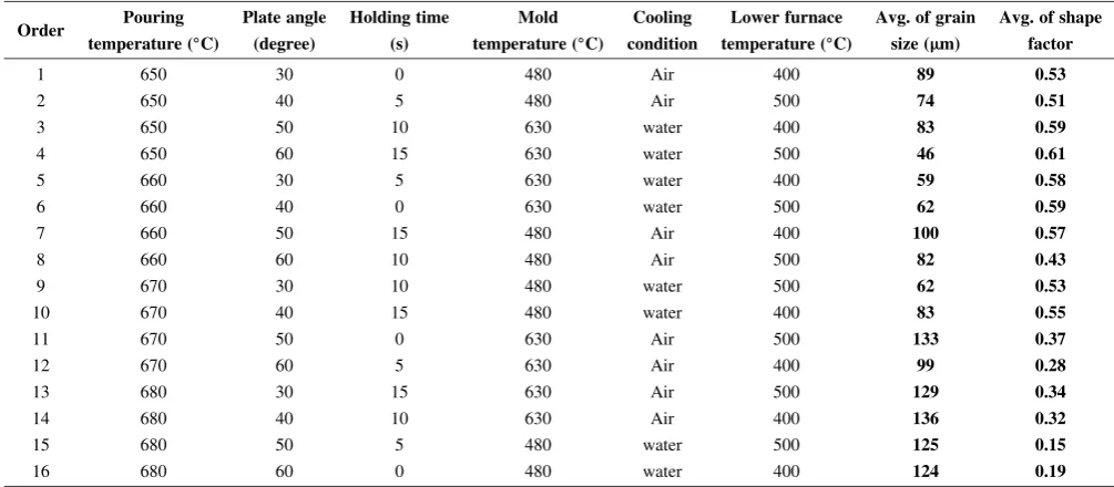
Table 2 L16(4424) orthogonal array and measured values.
Order Pouring Plate angle Holding time Mold Cooling Lower furnace Avg. of grain Avg. of shape
temperature (C) (degree) (s) temperature (C) condition temperature (C) size (m) factor
1 650 30 0 480 Air 400 89 0.53
2 650 40 5 480 Air 500 74 0.51
3 650 50 10 630 water 400 83 0.59
4 650 60 15 630 water 500 46 0.61
5 660 30 5 630 water 400 59 0.58
6 660 40 0 630 water 500 62 0.59
7 660 50 15 480 Air 400 100 0.57
8 660 60 10 480 Air 500 82 0.43
9 670 30 10 480 water 500 62 0.53
10 670 40 15 480 water 400 83 0.55
11 670 50 0 630 Air 500 133 0.37
12 670 60 5 630 Air 400 99 0.28
13 680 30 15 630 Air 500 129 0.34
14 680 40 10 630 Air 400 136 0.32
15 680 50 5 480 water 500 125 0.15
[image:2.595.47.290.84.185.2]16 680 60 0 480 water 400 124 0.19
Table 1 Product parameters and their levels.
Parameters unit Level
1 2 3 4
Pouring Temperature C 650 660 670 680
Angle of cooling plate degree 30 40 50 60 Holding time s 0 5 10 15 Mould temperature C 480 630 — —
Cooling condition — air water — — Lower furnace temperature C 400 500 — —
Table 3 The results of analysis of variation for the grain size.
Parameters DF Seq. SS Adj. SS Adj. MS F P
Pouring Temperature 3 7837.3 7837.3 2612.4 41.41 0.006 Cooling plate angle 3 1644.3 1644.3 548.3 8.69 0.054 Holding time 3 449.3 449.3 149.3 2.37 0.248 Mold temperatures 1 4.0 4.0 4.0 0.817 0.817 Cooing condition 1 2450.0 2450.0 2450.2 38.84 0.008 Lower furnace temperature 1 225.0 225.0 225.0 3.57 0.155
Error 3 189.2 189.2 63.1 Total 15 12799.8
Table 4 The results of analysis of variation for the shape factor.
Parameters DF Seq. SS Adj. SS Adj. MS F P
Pouring Temperature 3 0.243625 0.243625 0.081208 74.39 0.003 Cooling plate angle 3 0.039725 0.039725 0.013242 12.13 0.035 Holding time 3 0.042425 0.042425 0.014142 12.95 0.032 Mold temperatures 1 0.003025 0.003025 0.003025 2.77 0.195 Cooing condition 1 0.012100 0.012100 0.012100 11.08 0.045 Lower furnace temperature 1 0.000400 0.000400 0.000400 0.37 0.588
Error 3 0.003275 0.003275 0.001092 Total 15 0.344575
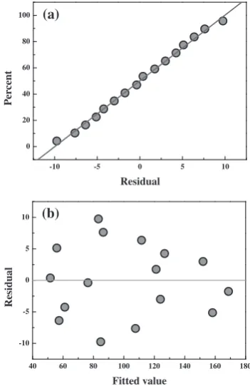
[image:2.595.45.548.410.630.2] [image:2.595.44.291.671.786.2] [image:2.595.304.548.671.785.2]All of data are supposed a normal distribution in statisti-cally procedure. It is necessary to confirm a normal distribution for a obtained data. If a strong relationship between scattered data points and their regression line in normal distribution plot, it shows that the obtained data can be use for a statical analysis. Residual analysis for reliability consists of analyzing the results of an ANOVA by assigning residual values to each data point in the data set. A Fitted Value plot helps to detect a not-modeled behavior in the underlying relationship. The residual plots of residuals for the grain size are presented in Fig. 3. And the normal probability plot is presented in Fig. 3(a). It can be noticed that the residuals fall on a straight line, which means that the residuals are normally distributed. Figure 3(b) shows the residual values with fitted values for grain size of semi solid ingot. Figure 3(b) indicates that maximum variation of10
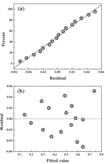
to 10, which shows the high correlation between fitted valued and observed values. Similarly, Fig. 3 displays the residual plots for shape factor. The normal distribution of residuals for shape factor is presented in Fig. 4(a). It is observed that the residuals are distributed normally and a straight line is adequate. The fitted values versus the residuals are presented in Fig. 4(b). The residuals observed are from0:05to 0.05, which also shows the high correlation between experimental parameters and shape factor.
The affecting ratio of employed parameters in this paper is listed in Table 5. The affecting ratio was calculated by sum of squares of deviation (Sqe. SS), in order to quantify the degree of effect of the parameters on microstructure characteristic of cooling plate casting ingot.12)The influence of pouring temperature is largest among the six parameters as the results of ANOVA in Table 5. In the case of grain size,
the affecting ratio of the pouring temperature is 61% and the water-cooled plate is 9%. This results show that the micro-structure with fine grain can be taken if the melt having a low temperature is poured on water-cooled cooling plate and the globular grain can be obtained by cooling plate angle and
Fig. 2 Microstructures of ingots fabricated according to the table of L16(4424) orthogonal array12)
-10 -5 0 5 10
0 20 40 60 80 100
P
er
cent
Residual
40 60 80 100 120 140 160 180 -10
-5 0 5 10
Residual
Fitted value (a)
(b)
[image:3.595.119.477.71.375.2] [image:3.595.337.513.410.681.2]holding time. The affecting ratio of pouring temperature for shape factor is 71%. The results of ANOVA show that all of the employed product parameters in previous studies are statistically insignificant. Thus, the microstructure of semi solid ingot can be obtained by controlling the parameters having the significance of level in statistics. In accordance with the above ANOVA results, the pouring temperature was defined as the main significant factor for billets in the cooling plate method, indicating that the microstructures of the SSM billets can be changed easily when this temperature is not controlled.
Ohno and Motegi1,2)also reported that, in order to obtain a
fine equiaxed structure, the separation of crystals should be promoted in the liquid with a low under-cooling, and the pouring temperature of the alloy must be as low as possible to prevent remelting of the free crystals in the liquid. They identified the pouring temperature to be the most significant factor in the cooling plate method for fabricating SSM billets. These results show that the crystals remaining in the mold
were separated in the melts with a low under-cooling using the cooling plate and that the primary direction of growth can be prevented because the distance of the adjacent grains was reduced by many of the crystals separated from the cooling plate. Therefore, a low pouring temperature is preferred in terms of the cooling ability of the cooling plate. The cooling plate could cool the melt to just below the liquidus temper-ature of the alloy, which stabilized the initial size of the primary crystals so that they were able to survive and grow in the liquid after being poured into the mould.
3.2 Effect of cooling plate and holding time
The cooling rate also is considerable parameter with effect on microstructure of casting ingot. Conventionally, equiaxed grain can be formed at a low cooling rate. The cooling rate of below 0.2C/s also can form the equiaxed grain in previous
studies.13,14)Therefore, the temperature of mold and furnace
is used to control the cooling rate and effect of cooling rate on microstructure of semi solid Al-Zn-Mg alloy was confirmed. The temperature of mold and furnace was hold at 570 and 630C and the parameters with effect on grain size and shape
factor was employed as the melts was poured at 650C, water
cooled plate with tilted 30 deg into the mold at given condition. The microstructures were observed with in-creasing holding time as 60 s, 300 s, 600 s and 1200 s. For comparing with effect of a low pouring temperature on microstructure, the casting was carried out at given condition without cooling plate.
The measured cooling rate of the melts was 0.02 and 0.003C/s, respectively, at mold temperature of 570 and
630C. These two cooling rate were enough to form the
equiaxed structure. The cooling rate was dropped with increasing the holding temperature. The change of the microstructure during maintenance in the furnace was displayed in the Figs. 5 and 6.
In Fig. 5, the grains with rosette morphology were appeared at the holding time of 60 s and grains became to be equiaxed grains at holding time of 600 s. When cooling plate is not used (Fig. 6), however, the morphology of grain was a large rosette type, equiaxed grain was not appeared. The difference in microstructure evolution was clearly revealed from Fig. 6 with cooling rate of 0.003C/s. The observed morphology was more rosettes typed in both of specimens since a higher maintenance temperature. How-ever, cooling plate cast ingot has a many of grains just at 60 s, and continuously became to be equiaxed grain. In other hands, the microstructure of ingot without cooling plate was dendritic structure by 600 s, although the pouring temper-ature was lower than a conventional pouring tempertemper-ature. These results show that the remaining crystals in the mould were separated in melts with a low under-cooling by using the cooling plate and that the preferred-direction growth can be prevented because the distance of the adjacent grains was reduced by many of crystals separated from the cooling plate.
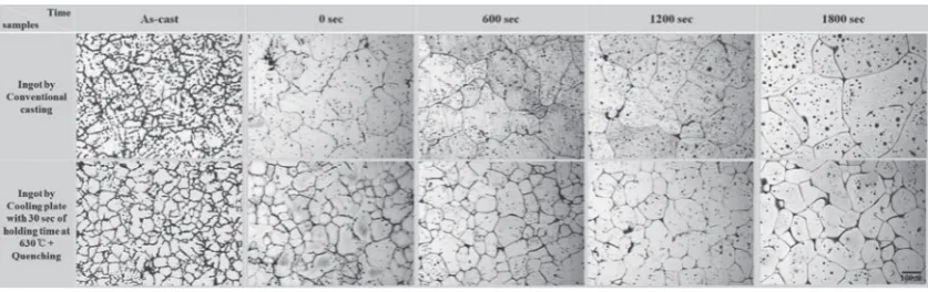
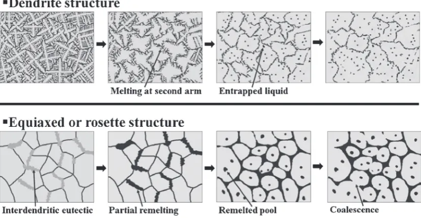
3.3 Microstructure evolution during reheating process In Fig. 7, a gradual grain growth with increasing holding time is shown. The dendritic structures were transformed into grains during isothermal holding at 615C, and entrapped -0.06 -0.04 -0.02 0.00 0.02 0.04 0.06
0 20 40 60 80 100 Pe rc en t Residual
0.1 0.2 0.3 0.4 0.5 0.6 0.7 0.8 -0.06 -0.04 -0.02 0.00 0.02 0.04 0.06 Residual Fitted value (a) (b)
[image:4.595.82.258.68.341.2]Fig. 4 The normal probability and fitted value for shape factor. (a) Normal probability plot, (b) Fitted value for residual
Table 5 The affecting ratio of each parameter.
Parameters
Grain size Shape factor
Seq. SS Affecting
ratio (%) Seq. SS
Affecting ratio (%)
Pouring Temperature 7837.3 61.23 0.243625 70.70 Cooling plate angle 1644.3 9.26 0.039725 11.53 Holding time 449.3 1.33 0.042425 12.31 Mold temperature 4 0.01 0.003025 0.88 Cooing condtition 2450 1.82 0.012100 3.51 Lower furnace temperature 225 0.08 0.000400 0.12 Error 189.2 0.04 0.003275 0.95 Total 12609.9 100 0.3413 100
[image:4.595.46.291.399.538.2]liquids appeared in the grains. In addition, the billets with rosette-type structures maintained a more polygonal mor-phology while the shape factor that was developed through isothermal holding time and interdendritic eutectic phase disappeared in early stage of reheating. A remelted phase surrounding the grains and remelted pools in the billets appeared after an isothermal holding time of 30 min. The grain size was limited to 110mmafter 30 min of isothermal holding in SSM billets but growth of the conventional casting billet occurred rapidly at the initial stage of reheating, to give a grain size of 250mm. During the partial remelting, the difference between the dendritic and rosette-type structures
was attributed to the globalization mechanism in which the rapidly grown grains became coarsened grains by calescence of the second dendrite arms in the early stage. However, in the case of the SSM billets, the rosette-type structure was quickly changed into polygonal grains by interdendritic eutectic phase melting and grain growth was prevented and globalized by wetting melt and grains in order to reduce the solid/liquid interface energy. This was explained in Fig. 8 by the fact that the principal mechanism of grain growth in the early stage was coalescence of the second dendrite arms in the case of dendritic structures, while Ostwald ripening became the main mechanism with increasing reheating time.
60s 300s 600s 1200s
Cooling rate of 0.02 °
°C/s
Using cooling plate
W
ithout cooling plate
200 mµ
Fig. 5 Change in the microstucture with increasing holding time in the different process, when the cooling ratio is 0.02C/s.
60s 300s 600s 1200s
Cooling rate of 0.003 °
°C/s
Using cooling plate
W
ithout cooling plate
200 µ m
Fig. 6 Change in the microstucture with increasing holding time in the different process, when the cooling ratio is 0.003C/s.
[image:5.595.89.513.73.234.2] [image:5.595.90.508.275.435.2] [image:5.595.88.507.475.607.2]For the rosette-type grain, interdendritic eutectic phase was remelted in the early stage by diffusion of solute elements and its coalescence, leading to insignificant grain growth but globalization occurred in order to reduce the interfacial area of the solid/liquid. Extended reheating time might induce coalescence between two grains.
When the melts were kept isothermally in the heated mold, the solute elements were transported to the liquid phase with increasing holding time, leading to a larger difference in concentration between the grains and eutectic phase due to the increasing diffusion rate of Zn, Mg and Cu etc.15)
Therefore, the present billets with rosette type structures increased the constitutional difference in Zn, Mg and Cu between the grains and interdendritic phase, which may have induced previous partial remelting of the interdendritic eutectic phase when reheated into the solid/liquid range of the alloy. This may have advantages in the thixoforming process because the grain growth rate was low and the reaction occurred at the solid/liquid interface.
4. Conclusions
In this study, the effect of parameters on microstructure Al-Zn-Mg alloy by cooling plate method was analyzed by analysis of variance. The result can be summarized to;
(1) The results from ANOVA showed that the pouring temperature is the main effect factor in the cooling plate method. In order to obtain SSM billets with an acceptable level of reproducibility, the pouring temper-ature was set to a superheatðTÞ<20C to induce the
formation of separate crystals on the cooling plate and support crystal growth in the mold.
(2) The cooling plate cast semi solid Al-Zn-Mg alloy ingot had rosette type structures and were produced at a pouring temperature with a superheat of 10C, a water-cooled plate and a 60 s holding time in the mold. Also, the extended holding time after pouring allow to be globular grain.
(3) In the reheating process, compared with conventional cast ingots with dendritic structures, the rosette-type structures were transformed into polygonal grains in the early stage of reheating by remelting of the interden-dritic eutectic phase because of the different concen-trations of the solute elements. This billet has a promising potential for application to the feedstock for thixoforming.
Acknowledgement
This research was financially supported by the Ministry of Education, Science Technology (MEST) and Korea Institute for Advancement of Technology (KIAT) through the Human Resource Training Project for Regional Innovation.
REFERENCES
1) A. Ohno:Solidification, (Springer-Verlag, Tokyo, 1987).
2) T. Motegi, K. Kondou, C. Liu and S. Aoyama: Proc. 4th Decennial Int. Conf. on Solidification Processing, (1997) p. 7.
3) J. P. Eom, D. H. Jang, S. G. Lim, D. G. Kim and D. E. Yoon: J. Korean Foundrymen’s Soc.16(1996) 538–544.
4) K. S. Kim and S. G. Lim: J. Kor. Inst. Met. Mater.38(2000) 529–533. 5) F. Tanabe, T. Motegi and E. Sugiura: J. JILM53(2003) 290–294. 6) H. Shimada, F. Kido and T. Motegi: J. JILM58(2008) 295–298. 7) T. Haga and S. Suzuki: J. Mater. Process Technol.118(2001) 169–172. 8) Y. Birol: J. Mater. Process Technol.186(2007) 94–101.
9) Barnes and J. Wesley:Statistical Analysis for Engineers and Scientists, (McGraw Hill, New York, 1994).
10) R. K. Roy:Design of Experiments Using the Taguchi Approach, (John Wiley & Sons, Inc. New York, 2001).
11) J. Dong, S. S. Cui, Q. C. Le and G. M. Lu: Mater. Sci. Eng. A345
(2003) 234–242.
12) J. Y. Ahn, D. E. Kim, J. Y. Choi and K. H. Shin: J. of Kor. Soc. Precision Eng.20(2003) 143–149.
13) W. W. Mullins: J. Appl. Phys.34(1963) 323–329. 14) K. Xia and G. Tausig: Mater. Sci. Eng. A246(1998) 1–10. 15) M. Adachi, S. Sato, H. Sasaki, Y. Harada, N. Ishimashi and T.
Kawasaki: J. JILM58(2008) 421–427.
16) E. J. Zoqui and M. H. Robert: J. Mater. Process Technol.109(2001) 215–219.
Fig. 8 Proposed mechanism for the evolution of dendritic to globular structure when dendritic structures16)and rosette-type structures
following reheating.
[image:6.595.91.505.76.290.2]