Influence of Dog-Bone Width on End Profile in Plan View Pattern Control Method
in Plate Rolling
*1Masayuki Horie
*2, Kenji Hirata, Junichi Tateno and Naoki Nakata
Steel Research Laboratory, JFE Steel Corp., Fukuyama 721–8510, Japan
A plan view pattern control method for plate rolling called the Mizushima Automatic Plan View Pattern Control System (MAS) or Dog Bone Rolling (DBR) was developed. In this method, the slab is given a non-uniform thickness profile in the width direction to obtain non-uni-form elongation at following flat rolling. In order to make the plate more rectangular under various rolling conditions, prediction of elongation at following flat rolling is necessary. In this research, the influence of the width of the dog-bone (overly thick part at the slab width edge) on the fish-tail length (over-elongation at the slab end) is investigated. The fish-tail length increases as the dog-bone width increases and the dog-bone width ratio decreases. These phenomena are related to the following behavior of the restriction of excessive elongation in the dog-bone because of existence of unrolled volume before roll gap entrance: As the dog-bone width increases and the dog-bone width ratio decreases, the working length of restricting stress increases. Hence, restricting stress is released earlier and the rolling length for fish-tail formation increases. As a re-sult, the fish-tail length increases. Therefore, in prediction of the plan view pattern, not only the dog-bone thickness, but also the dog-bone width and dog-bone width ratio should be considered. [doi:10.2320/matertrans.P-M2017805]
(Received May 11, 2016; Accepted January 5, 2017; Published February 24, 2017)
Keywords: rolling, plate rolling, deformation behavior, model simulation, FEM, plan view pattern control, dog-bone width, crop length, mizushima automatic plan view pattern control system (MAS), dog bone rolling (DBR)
1. Introduction
In rolling, non-uniform deformation occurs at head and tail ends of the rolled slab. And the plan view pattern of the rolled slab becomes concave at length end and convex at width end. In plate rolling, this non-uniform deformation becomes larger as the ratio of the slab thickness and the roll radius becomes larger. In addition, slabs are rolled in the width direction as broad side rolling, so concave profile appears at the length end and convex profile appears at width end of rolled plates. Thereby, the plan view pattern of rolled plates becomes com-plicated because convex and concave are combined1). Fur-thermore, the end profile is varied with thickness reduction in broad side rolling and longitudinal rolling2,3). This non-rect-angular profile at the width end is called width deviation and the profile at the length end is called crop . These parts of the plate are cut off in order to obtain a rectangular plate shape, and this results in yield loss.
Therefore, a plan view pattern control method was devel-oped in order to obtain a near-rectangular end profile. In this method, the slab is given a non-uniform thickness profile by changing the roll gap at the pass before turning to obtain non-uniform elongation in the width direction at the pass af-ter 90 turning. This method is applied widely under the names Mizushima Automatic Plan View Pattern Control Sys-tem (MAS)4) or Dog Bone Rolling (DBR)5). The thickness profile after turning in this method is called dog-bone because flat part is formed at the width center and overly thick part is formed at the width edge. This dog-bone profile is controlled so as to make the plate closer to a rectangular shape in plan view pattern.
Recently, with upsizing of structures such as ships in which plate products are used, the thickness of plate products has
increased. In addition toughness and other mechanical prop-erties have become higher. Therefore, the rolling pass sched-ule is changed, for example reheating temperature is reduced and controlled rolling is applied. As a result, the plan view pattern has changed from that of when the method was devel-oped.
The relationship between the dog-bone profile and crop profile after rolling was reported as follows. In MAS rolling, elongation is proportional to the thickness before flat rolling, following the volume constancy law, because the difference in thickness in width direction is small4). In DBR, from the experimental results with the slab which has the same dog-bone width, the optimum dog-dog-bone height is larger than that calculated from the volume constancy law, and a correction factor was proposed5). On the other hand, there are reports which show the length end profile of rolled plate when the slab has thickness profile calculated from volume constancy law. Their end profiles are close to rectangular but still con-vex6,7). And Hirata et al. reported the results that fish-tail length is changed with dog-bone width though the difference in thickness is identical8). Thus, there is some possibility to get more rectangular plate for different plan view pattern in these days.
Also, plan view pattern prediction was investigated in edg-ing process that is another plan view pattern control method. Edging process includes a vertical rolling and a horizontal rolling. Plate width is reduced and dog-bone shape forms during vertical rolling, and the dog- bone shape is flattened in horizontal rolling. And there are reports which show the influ-ences of edging amount on crop length9–12). But, its dog-bone profile is different from the profile formed in roll gap chang-ing method in the followchang-ing points: On its dog-bone shape, maximum height exists inside the end of width. And the dog-bone width is smaller and the thickness changes steeply in width direction13,14). So, the crop profile formed in dog-bone flattening is different in the dog-bone which is formed in roll gap changing and during vertical rolling.
*1
This Paper was Originally Published in Japanese in J. JSTP 57 (2016) 347–352.
*2
In this paper, the influence of the dog-bone width and its ratio to the plate width on fish-tail length, which represents plan view pattern, is investigated in a rolling experiment with a lead slab, and the reason why the fish-tail length differs with the dog-bone width and its ratio to the plate width is investi-gated by Finite-Element (FE) analysis.
2. Outline of Plan View Pattern Control Method
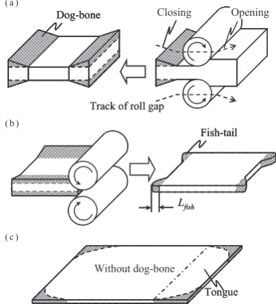
Figure 1 shows the outline of the plan view pattern control method taken up in this paper. In plate rolling, a slab is turned 90 after rolling in the width direction of the rolled plate, and the slab is rolled in the longitudinal direction to obtain the required size. In general, unsteady deformation of the end causes smaller elongation around the width edge, and its end profile becomes convex, as shown in the white part in Fig. 1(c). This profile is called tongue.
Firstly, in the final pass of broad side rolling, a dog-bone is formed by changing the roll gap during rolling (Step 1). Next, this slab is turned and rolled in the longitudinal direction (Step 2). In this pass, excessive elongation occurs in the dog-bone part where the entry thickness is larger than that at other parts. This profile is called fish-tail. Following this, as Step 3, the slab is rolled to the required thickness by several reverse passes. The end profile becomes rectangular because the tongue obtained in longitudinal direction rolling is added to the fish-tail formed in Step 2. So the dog-bone profile should be determined to obtain intended fish-tail profile to get rect-angular plate, and the plan view pattern after dog-bone flat-tening should be predicted in high accuracy.
Figure 2 shows the configuration of bone. The dog-bone profile is defined by its height HDB and width WDB.
Yanazawa et al. reported that the difference in elongation is proportional to the difference in thickness because the differ-ence in thickness is small in this plan view pattern control method. Therefore, the fish-tail length conforms to the
vol-ume constancy law4), and the fish-tail length L
fish is expressed
by delivery thickness Hout and delivery length l1, as shown in
eq. (1). In this equation, the influence of the dog-bone width WDB is not considered.
Lf ish=Hl1
out ·HDB (1)
Haga et al. investigated the influence of the dog-bone height HDB on crop loss under various rolling patterns with
the same dog-bone width WDB slabs, and reported that the
optimum dog-bone height H* is larger than the height calcu-lated from the volume constancy law H5). This difference is caused by the difference in width spread ratio at width edge, and the ratio of H* to H is defined as the width spread correc-tion factor α (α > 1). Thus, the fish-tail length Lfish is shown
by the following equation.
Lf ish= 1
α· l1
Hout ·HDB= H H∗ ·
l1
Hout ·HDB (2) Since H is smaller than H*, the correction factor is larger than unity. This correction factor α becomes larger with de-crease in thickness, but is not changed with the slab width.
As mentioned above, the influence of the slab size and dog-bone height HDB on the fish-tail length Lfish has been clarified,
but the influence of the dog-bone width WDB has not been
vestigated. Therefore, the influence of dog-bone profile in-cluding dog-bone width on the end profile should be investi-gated.
3. Rolling Experiment
3.1 Experimental procedure
The influence of the dog-bone profile on the end profile was investigated by rolling experiments. As the pass in Step 2 in Fig. 1, a lead slab with a machined dog-bone was rolled, and the profiles of length end were measured. The roll diam-eter is 120 mm, the roll barrel length is 300 mm and the roll-ing speed is 60 mm/s. The slab and dog-bone sizes are shown in Table 1. In this experiment, the dog-bone width WDB and
slab width W were varied between cases, and the slab length, thickness and dog-bone height were constant. In cases 1 to 3, the dog-bone widths and slab widths were varied under the condition that the ratio of the dog-bone width to the slab width (dog-bone width ratio WDB/W) is 0.26 so as to keep the identical ratio of the dog-bone area to the whole area. In cases 1 and 4 to 6, the dog-bone width ratios were varied with the constant dog-bone widths and different slab widths to keep the constant dog-bone area.
Fig. 1 Schematic of plan view pattern control method. (a) Step 1: Final pass of broad side rolling, (b) Step 2: First pass of longitudinal rolling, (c)
[image:2.595.65.267.529.751.2] [image:2.595.330.526.691.770.2]3.2 Experimental results
Figure 3 shows an example of the head and tail end pro-files. This is the result in the case of a 40 mm dog-bone width and 150 mm slab width (case 1). The elongation is large at the dog-bone part where the entry thickness is large, and elonga-tion is reduced as going toward the width center even in the constant entry thickness part. As a result, the end profile has a fish-tail shape. The length shows its maximum on slightly in-terior side of the width edge and its minimum at the width center. The tail end profile is 3 times longer than the head end profile, while the shapes of the two profiles are similar. In this paper, the difference between the maximum and minimum length in the tail-end profile is defined as the fish-tail length Lfish.
Figure 4 shows the relationship between the dog-bone width and fish-tail length in cases 1 to 3, in which the dog-bone width ratio is identical. The fish-tail length becomes
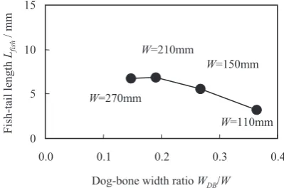
longer as the dog-bone width increases, even though their cross-sectional shapes are similar. Figure 5 shows the rela-tionship between the dog-bone width ratio and the fish-tail length in cases 1 and 4 to 6, in which the dog-bone width is identical. The fish-tail length is not changed when the dog-bone width ratio is less than 0.20, but becomes shorter as the dog-bone width increases where it is over 0.20.
In eq. (1) and eq. (2), the fish-tail length is constant when the slab thickness, width and dog-bone height are the same. However, in these experimental results, the fish-tail length is varied with the dog-bone width and the dog-bone width ratio. Moreover, the fish-tail length is varied with the dog-bone width ratio even when the dog-bone width is the same. So, the fact that dog-bone width and the dog-bone width ratio influ-ence on the fish-tail length has been clarified.
4. FE Analysis
4.1 Analysis procedure
The reason why the fish-tail length is varied with the dog-bone width and the dog-dog-bone width ratio was investigated by FE analysis. Rolling pass under the same conditions with the experiment was simulated by ABAQUS explicit (ver.6.11). A quarter part of the slab is divided into 8 node hexahedron ele-ments. The element length is 1 mm in order to divide the roll contact length into 10 elements, and the number of elements in the slabs is 180,000 to 450,000. The mass-scaling factor is 1500 to shorten the calculation time. The rolls are rigid bod-ies, and the slab is an elastic-plastic material. Figure 6 shows the stress-strain relationship of the slab materials. That is ex-Table 1 Experimental conditions.
Case number 1 2 3 4 5 6
Slab length L0 mm 500
Slab thickness Entry Hin mm 12.0
Delivery Hout mm 10.5
Dog-bone height HDB mm 1.0
Dog-bone width WDB mm 40 55 70 40
Slab width W mm 150 210 270 110 210 270
Dog-bone width ratio WDB/W 0.26 0.36 0.19 0.15
Fig. 3 Example of end profile (Case 1 : WDB = 40 mm, W = 150 mm).
Fig. 4 Influence of dog-bone width WDB on fish-tail length (dog-bone width ratio WDB/W = 0.26).
Fig. 5 Influence of dog-bone width ratio WDB/W on fish-tail length (dog-bone width WDB = 40 mm).
[image:3.595.62.271.399.587.2] [image:3.595.325.525.450.582.2] [image:3.595.67.268.631.761.2] [image:3.595.325.525.642.771.2]pressed by a multi-line curve made from the results in com-pression test, and that depends on the strain rate. Table 2 shows the other material properties. The friction between the roll and slab is given by Coulomb s friction law, and the fric-tion coefficient is 0.4.
4.2 Analysis results
Figure 7 shows the fish-tail length in the experiment and FE analysis. Figure 7(a) shows the results in different dog-bone widths (cases 1–3), and Fig. 7(b) shows the results in the different dog-bone width ratios (cases 1 and 4–6). In the FE analysis results, the fish-tail length becomes longer as the dog-bone width increases or the dog-bone width ratio de-creases; this is the same as the experimental results, and the amount of the fish-tail length is also almost the same as in the experimental results.
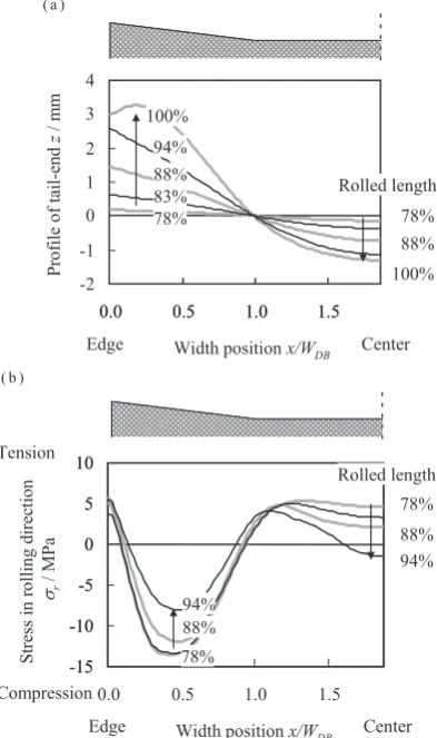
Figure 8 shows the change in the tail end profile and stress in the rolling direction at the entry of roll bite during rolling. The progress of rolling is indicated by rolled length as the ratio to the slab length. The profile of the tail end is shifted to 0 representing the boundary between the dog-bone part and the flat part. As shown in Fig. 8(a), the tail end profile is flat until the rolled length of 78%. When rolled length becomes over 78%, the elongation of the dog-bone part increases and that of the flat part decreases, resulting in the formation of a fish-tail. As shown in Fig. 8(b), at the rolled length of 78%,
the stress in the dog-bone part is compressive and that in the flat part is tensile. With the progress of rolling, these stresses decrease. That is, when the rolled length is small, the differ-ence in elongation caused by the differdiffer-ence in the thickness reduction is restricted by the slab on entry side, and large compressive stress in rolling direction appears at dog-bone part. However, with progress of rolling, restriction by the slab on entry side weakens as slab length on entry side decreases. As a result, a fish-tail is formed due to the appearance of a difference in elongation.
Therefore, the distribution of stress in the rolling direction was investigated in detail. Figure 9 shows the distribution of stress under different dog-bone width and dog-bone width ra-tio condira-tions. Here, the rolling length is 50%, which means a sufficiently long slab exists on the entry side. In all cases of Fig. 9(a) to (c), the stress is compressive in the dog-bone part and tensile in the flat part, and decreases with distance from the roll bite. So, the working region of compressive stress, which restricts excessive elongation in the dog-bone part, is compared. Comparing Fig. 9(a) and (b), in which the dog-bone widths are different, compressive stress works widely and longer when the dog-bone width is wider (Fig. 9(a)). Comparing Fig. 9(b) and (c), in which the dog-bone width ratios are different, compressive stress works longer when the dog-bone width ratio is smaller (Fig. 9(c)), but it works at the identical width.
As mentioned above, distribution of compressive stress
Table 2 Material properties of slab used in FE analysis.
Young s modulus E/MPa 16000
Poisson s ratio ν 0.44
Yield stress σe/MPa 0.8
Density ρ/kg・m−3 11300
Fig. 7 Comparison of fish-tail length obtained in experiment and FE analy-sis. (a) Dog-bone width ratio WDB/W = 0.26, (b) Dog-bone width WDB = 40 mm.
Fig. 8 Change in fish-tail profile and stress in pass (Case 1: WDB = 40 mm,
[image:4.595.329.526.418.750.2] [image:4.595.88.253.433.752.2]which restricts excessive elongation of dog-bone part is dif-ferent with dog-bone width and dog-bone width ratio. And, the length of working region is larger in the case of larger dog-bone width or smaller dog-bone width ratio.
4.3 Discussion
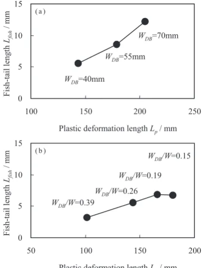
The working length of compressive stress is different with the dog-bone width and dog-bone width ratio. To clarify the influence of compressive stress on the fish-tail length, the working length in the FE analysis and the fish-tail length in the experiment are compared. The working length of com-pressive stress is defined as the plastic deformation length at the rolled length of 50%. The plastic deformation length is the distance from the entry of roll bite to the point where the plastic deformation occurred at slab on entry side. Figure 10 shows the relationship between the plastic deformation length and the fish-tail length. In the case of different dog-bone widths, the plastic deformation length becomes larger as the dog-bone width increases, and the fish-tail length also in-creases as shown in Fig. 10(a). In the case of different dog-bone width ratios, the plastic deformation length becomes larger as the dog-bone width ratio decreases, and the fish-tail length increases as shown in Fig. 10(b).
As mentioned above, as the dog-bone width increases or the dog-bone width ratio decrease, the working length of compressive stress increases. This means that the length of slab on entry side which restricts excessive elongation at dog-bone part, increases. So, the restriction is released earlier in the pass and the rolling length for fish-tail formation becomes larger. As a result, the fish-tail length becomes larger.
5. Conclusion
In the plan view pattern control method for plate rolling, the influence of the dog-bone width on the fish-tail length was clarified by a rolling experiment and FE analysis as follows.
(1) The fish-tail length increases as the dog-bone width in-creases and the dog-bone width ratio dein-creases. This is
differ-ent from the convdiffer-entional phenomena following the volume constancy law.
(2) Fish-tail is formed as a result of the release of the stress in rolling direction, which restricts the difference in elonga-tion caused by the difference in thickness reducelonga-tion as the slab length on entry side decreases.
(3) The fish-tail length is influenced by the dog-done width and the dog-bone width ratio because they cause the differ-ence in the distribution of the stress in rolling direction at Fig. 9 Contour of stress in rolling direction (σr) when half length of slab is rolled. (a) Case 3, W = 270 mm, WDB = 70 mm, WDB/W = 026, (b) Case 1, W =
[image:5.595.79.515.70.282.2]150 mm, WDB = 40 mm, WDB/W = 026, (c) Case 6, W = 270 mm, WDB = 40 mm, WDB/W = 015.
[image:5.595.324.527.333.602.2]entry side. Therefore, for the prediction of the plan view pat-tern, both the dog-bone width and dog-bone width ratio should be considered.
REFERENCES
1) H. Suzuki: Atsuen Hyakuwa, (Youkendo, Tokyo, 2000) p.48.
2) M. Takumi, Y. Naba, K. Omata, S. Tanimoto and H. Tsukamoto: Proc. Int. Conf. Steel Rolling (1980) 331–343.
3) J.H. Ruan, L.W. Zhang, S.D. Gu, W.B. He and S.H. Chen: Ironmaking Steelmaking 41 (2014) 656–664.
4) T. Yanazawa, J. Miyoshi, K. Tsubota, H. Kikugawa, T. Ikeya, S. Isoya-ma, I. Asahi and K. Baba: Kawasaki Steel Giho 11 (1979) 168–181. 5) Y. Haga, Y. Ogawa, M. Yamawaki, S. Murakami, T. Matsuo and S.
Ma-suda: Nippon Kokan Tech. Rep. 98 (1983) 13–23.
6) Y. Zhao, Q. Yang, A. He, X. Wang and Y. Zhang: J. Iron and Steel Re-search Int. 18 (2011) 26–30.
7) J. Ruan, L. Zhang, S. Gu and J. Zhang: Int. J. Materials and Product Technology 47 (2013) 103–125.
8) K. Hirata, M. Horie, Y. Takashima and T. Udagawa: Proc. 2002 Spring
Conf. Jpn. Soc. Technol. Plast., (2002) pp. 227–228.
9) S. Sasaji, K. Kutsuwa, A. Horibe, Y. Nohara, T. Yamada and K. Wata-nabe: Tetsu-to-Hagané 67 (1981) 2395–2404.
10) M. Nishizaki, I. Kokubo, H. Hayakawa, H. Kawatani, M. Fukuda and Y. Yoshima: Tetsu-to-Hagané 67 (1981) 2405–2411.
11) H. Furukawa, I. Ueda, K. Otake and N. Sakamoto: Proc. 7th Int. Conf.
Steel Rolling, (1998) pp. 538–588.
12) M.S. Chun and Y.H. Moon: Steel Res. 72 (2001) 17–23.
13) D. Yun, D. Lee, J. Kim and S. Hwang: ISIJ Int. 52 (2012) 1109–1117. 14) J.H. Ruan, L.W. Zhang, Z.G. Wang, T. Wang, Y.R. Li and Z.Q. Hao: