TRACKING SUB-PAGE COMPONENTS WITHIN
DOCUMENT WORKFLOWS
James A. Ollis, Steven R. Bagley and David F. Brailsford
Document Engineering Laboratory
School of Computer Science
University of Nottingham
Nottingham NG8 1BB, UK
{jao,srb,dfb}@cs.nott.ac.uk
ABSTRACT
Documents go through numerous transformations and intermediate formats as they are processed from abstract markup into final printable form. This notion of a document workflow is well established but it is common to find that ideas about document components, which might exist in the source code for the document, become completely lost within an amorphous, unstructured, page of PDF prior to being rendered. Given the importance of a component-based approach in Variable Data Printing (VDP) we have developed a collection of tools that allow information about the various transformations to be embedded at each stage in the workflow, together with a visualization tool that uses this embedded information to display the relationships between the various intermediate documents.
In this paper, we demonstrate these tools in the context of an example document workflow but the techniques described are widely applicable and would be easily adaptable to other workflows and for use in teaching tools to illustrate document component and VDP concepts.
Categories and Subject Descriptors
E.1 [Data]: Data Structures — Trees; I.7.2 [Document and Text Processing]: Document Preparation — Markup languages; I.7.4 [Document and Text Processing]: Electronic Publishing.
General Terms
Languages, DocumentationKeywords
XSLT, XSL-FO, PDF, document components, VDP, document workflows, Education
1. INTRODUCTION
It is increasingly the case that document creation, particularly in the business world, can be automated. Each document then becomes the output from a pipeline of processing and transformation stages. In these circumstances it becomes ever more difficult to trace which portions of the source document map into some given area on the output rasterized page.
Structural components such as paragraphs, diagrams, captions etc. are often identifiable in the document input language. These components may appear in some overtly XML-based format such as DocBook, which we shall use for illustrative purposes in this paper. But even in proprietary formats, such as MS Word, there is an increasing tendency to allow the inner structures to be exported as standardised XML notations. Unfortunately these structural entities, though identifiable by their rendered visual appearance, are often lost, in code-demarcation terms, within an amorphous final page of PDF. Even when the PDF COG model [1] has been used for the final page there has so far been no mechanism for tracing the transformation of source components into final-form COGs.
This can be likened to the effect of a traditional program language compiler. Here, the input language clearly delineates loops, conditionals, procedures, objects and data structures. But as the program is compiled these language structures are refined out and the result is an amorphous mass of generated machine code. Each stage of the compile chain (pre-processor, compiler, assembler, optimiser, linker) transforms part of the document.
We have developed a collection of tools that allows us to annotate the various intermediate document stages in a processing pipeline, as well as the final form document, with information regarding the various sub-page components and how they have been transformed. In later sections we also demonstrate a visualization tool for displaying the relationships between the different components of a document and how these fragments are transformed to produce the final output document.
2. DOCUMENT WORKFLOWS
Documents frequently undergo changes from one format to another as they progress from abstract markup to final printable form. This series of transformations is referred to as a Document Workflow and details the various formats and technologies used in producing the final form document.
Typically, a document workflow will start with a high-level representation that just considers the logical structure of the documentation (although with Variable Data Printing, it is common for the starting point to be a more abstract data representation [2]). This is then successively transformed through FINAL DRAFT of Short Paper accepted for
various stages with the structural information replaced with more presentational layout information and finally to a page description (e.g. PDF).
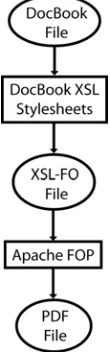
The work described in this paper is based around a workflow that uses DocBook [3] and XSL-FO [4] but the techniques described are generic to any XML-based workflow. Here, the transformations are described by XSLT scripts and the final transformation from XSL-FO to PDF being performed by Apache’s FOP [5] (an open-source FO processor written in Java). Figure 2.1 illustrates this workflow. The reasoning behind the selection of technologies used in this example workflow is purely practical. All of the tools used for the document transformations are open-source thereby allowing us to easily add new features.
The initial DocBook notation of the document describes it in terms of logical structure. DocBook defines a tagset in XML notation whereby books are split into chapters, which in turn contain sections that are further split into paragraphs and so on. This DocBook document is then transformed into an XSL-FO file through use of the DocBookXSL stylesheets [6]. These are a series of XSLT scripts that transform the logical structure of the DocBook file into a layout description of the document in XSL-FO markup. XSL-XSL-FO is concerned with specifying how ‘areas’ of content are laid out on the page, but it also allows for styling information about the content, such as fonts, colours etc. This extra styling and layout information is added into the document by the DocBook XSL stylesheets, which can therefore provide a default appearance for all generated documents. The final stage in the workflow is concerned with transforming the XSL-FO file into PDF. This is done using the Apache FOP processor, which lays out the various ‘areas’ in the document and produces the required PDF operators to produce the final output in the correct fonts and colours etc.
Note that the techniques and the resulting tools are applicable to a wide range of workflows and are not limited to the particular example discussed here.
3. TRACKING THE WORKFLOW
Each step of the document workflow can be considered as a function that takes some input and produces a new output. The generated content will consist of either transformed parts of source (for example, a marked-up paragraph in DocBook may be
transformed into an <fo:block/> or content generated by the transformation (the insertion of page numbers for example). To give an example, consider the following XML document (A):
<hello>world</hello>
that is transformed by the following XSLT script (T):
<xsl:stylesheet>
<xsl:template match=”hello”>
<goodbye>
<xsl:value-of select=’.’ />
</goodbye>
</xsl:template>
</xsl:stylesheet>
The product, T(A), from applying T to A would therefore be:
<goodbye>World</goodbye>
However, if we look only at the output, T(A), it is generally impossible to tell which part of A was the source for any given part of the output, even when, as in this case, T is just one simple transformation. A real-life document workflow would include numerous transformations of arbitrary complexity.
To enable the transformations to be visualized it is necessary to augment the output T(A), at every stage, with information that links each portion of the output to the corresponding part of the input, A. We have termed this extra information Generational Side-Bandinformation1 (GSBI) to signify that it is transmitted alongside the actual document content to track the way in which each piece of the document content has been generated). This can be considered analogous to the information [6] added by a compiler to the final executable to enable source-level debugging.
This leads to the question of where this extra information is stored. In the case of XML-XML transformations it is possible to embed the information into the XML output as attributes in some new namespace. For the final XML-PDF transformation, another approach must be taken.
3.1. Generational Side-Band Information
The GSBI stored on each generated node must at the very least be able to highlight the node in the source that was used to generate this given node, and preferably also details of the transformation that was used to generate it. Referring back to the example above, the <goodbye> node in T(A) needs to decorated with the information that it came from document A, and that more specifically it came from the <hello> node within document A.Fortunately, since each stage of the workflow produces an XML file (except, as we shall see, the final FOP stage, which produces a PDF), this information can be captured as an XPath expression. So, in the example above, the <goodbye> node’s source could be described by the following XPath:
document(uriToA)/hello[1]
1 [image:2.612.144.199.520.696.2]
The authors are aware that this is a gross misuse of the term side-band as used in telecommunications — we just like the name.
Note that since an XML element can have many children with the same name it is necessary to use an XPath predicate to ensure the correct node is selected.
Since the transformations are all XSLT-based (except, once again the final FOP stage), and are expressed in XML, it is possible to use a similar mechanism to express which part of the transformation script generated a given output node. These XPaths are much simpler than the ones relating to the source document and take the form:
/xsl:template[<predicate>]
where the predicate is specified as a series of tests on attribute names and values, ANDed together, that can uniquely identify the appropriate XSLT template. Only attributes that are relevant to the particular template are included and the list of possible attributes is limited to match, name, mode and priority. There is also the possibility that parameters may have been supplied to the template that would alter its execution, but for simplicity these have not been considered at the moment and are left as an exercise for the future.
So, once the GSBI has been calculated, it is necessary to annotate the generated XML with this information. The easiest storage option would be to place the GSBI onto each generated node as a set of attributes in their own gsbi: namespace. The format in which these attributes are stored is an important consideration since there may be an unknown number of transformations in the workflow for which this kind of information must be stored. The following format is used:
• There is a single attribute, gsbi:stages, that accumulates the names of the transformation stages as a space-separated list. This list defines the order in which the transformations have been applied, with the left-most stage being the first.
• All attributes relevant to a particular transformation stage are prefixed with the name of that stage.
The stage name is arbitrary since its sole purpose is to serve as a prefix for attributes describing a particular step in the workflow. This means that the stage name needs to be both unique and consistent across the whole output.
The set of attributes that are stored is dependent on the technology used in the transformation, but for XSLT transformations, we envisage storing the filename and XPath of the source node together with the filename and template node of the transformation script, as described previously. A final attribute,
gsbi:xxx_type (where xxx is the name of the stage), stores the type of the transformation performed. In our example case, this would simply be xslt, however other transformation tools may specify custom values (e.g. fop for Apache FOP transformations as discussed later).
At each subsequent stage in the document workflow, the existing GSBI attributes, generated by previous transformations, must be copied onto newly generated nodes, as well as adding the attributes regarding the current transformation. Therefore, in the final form document, the resulting components will have tracing information stored that describes every stage of the workflow.
4. XML-XML TRANSFORMATIONS
Since the GSBI data is to be stored as attributes on the XML source nodes, it falls to the XSLT script to generate these nodes in the same way that a compiler generates the debugging information appended to an object file.
There are two problems here: firstly, the transformation scripts are likely to have already been written without visualization in mind and so will require modification to support it. Secondly, and more crucial, altering the XSLT script to generate the GSBI attributes will require extensive modifications to the XSLT script that will cloud the desired operation of the script.
To understand this, consider the example XSLT transformation outlined in section 3. Here, the output document would need to be augmented as follows:
<goodbye gsbi:stages=”foo”
gsbi:foo_type=”xslt”
gsbi:foo_xpath=”document(a)/hello[1]”
gsbi:foo_transform=”/xsl:template[
match=’hello’]”>
World
</goodbye>
To generate the gsbi:stages attribute it is necessary to add the following XSLT section every time an XML node is added:
<xsl:attribute name=”gsbi:stages”>
<xsl:value-of select=”@gsbi:stages”/>
<xsl:value-of select=”$stage-id” />
</xsl:attribute>
The old attributes value (if present) is copied over, and the new stage identifier is added (this would be generated by another piece of XSLT code).
In the same way, the XPath of the current node would be need to be built up (XSLT provides no way of getting the XPath of the current node) and added as an attribute. The same is true for the transformation XPath.
Clearly, the amount of code to support the output is extensive and the possibility of errors to creeping in is high. Also, updating the XSLT script would be a complex task — a simple tweak to a templates match would now require modifying considerable amounts of code to ensure its output was still tagged correctly.
To avoid the tedium of making the numerous individual changes to the stylesheets by hand, it is possible to exploit the fact that XSLT scripts are themselves XML documents that could be transformed by yet another XSLT script. In this way a single “modifying” XSLT script can be used to adapt a whole range of similar “target” XSLT scripts. Once the nature of the modifications has been decided (i.e the format of the GSBI attributes) the easiest approach is to make this alteration to all
generated output tags. The key concept is that the modifying XSLT script is able to differentiate the ‘code generation’ portions in the target scripts from the controlling XSLT framework and thus it can arrange that all the code-generated tags are output with extra attributes.
5. XML-PDF TRANSFORMATIONS
The final transformation of the document workflow poses a unique problem. Up to this point the destination format has been another XML document, and so it has been possible to tag the generated XML nodes with the transformational attributes. However, the final stage of our example workflow produces a PDF document, which is not expressed in the XML metasyntax.
5.1. Tagging PDF
PDF as discussed in [1,9] describes each page as a monolithic stream of operators. This means that we are faced with the problem of how we ‘tag’ which part of the page has been generated by each source node. Two options exist, the first is to utilize the logical structure tree present in Tagged PDF [10] and the second would be to use the Component Object Graphic model [1]. Both approaches will require modifications to the XSL-FO processor (Apache FOP) to generate a modified form of PDF.
5.1.1. Logical
Structure
The Tagged PDF extensions enable a logical structure tree to be embedded within the PDF document. This can be considered equivalent to an XML structure, with the PCDATA at the leaves replaced by chunks of the PDF content stream (markers are placed within the content stream to denote specific regions). Support is included for both elements and attributes.
Therefore, a logical structure tree could be embedded within the generated PDF document that delineated the generated sections, and contained the attributes describing the source in the same manner as the XML documents.
5.1.2. Component-Object
Graphic
The PDF-COG model takes an alternative approach. Here, the page is no longer described as a monolithic stream of operators but rather as a series of discrete components (COGs), each completely encapsulated and separate from every other COG.
The destination of the final step of the document workflow is now a series of discrete COGs rather than an XML tree. This means that it is no longer possible to store the GSBI as attributes within a sideband namespace (at least, not without moving to some XML-ized version of PDF [11]).
However, this does not stop us tagging the COGs with the required GSBI. In [1] we explain that a COG is implemented within a COG-PDF file as a FormXObject. Each FormXObject
has a header dictionary (associative array) associated with it as shown in Listing 5.1.
/CogXXXXXX <<
/Type /XObject /Subtype /Form /Cogged true /Name /CogXXXXXX /Width 100 /Height 100 /Length 123
>>
Listing 5.1 — A typical COG
Fortunately, the PDF specification allows for the addition of domain-specific information to these dictionaries (indeed, the COG specification already makes use of this ability). Therefore, it is possible for us to include an additional dictionary containing the
GSBI for the visualizer software to access. Listing X.XX shows the modified structure. Another entry is added to the COG header (under the SourceInfo key) that contains the same data previously stored as attributes in the XML stages of the workflow. However, the data is now packaged as an array of dictionaries, one for each stage with the earliest transformation at index zero. So the transformation described in the example used in section 4, would be embedded in a COG as shown in Listing 5.2.
/CogXXXXXX <<
/Type /XObject /Subtype /Form /Cogged true /Name /CogXXXXXX /Width 100 /Height 100 /SourceInfo [
<<
/StageName /Foo /Type /XSLT /SourceXPath (…) /Transform (…) >>
... ]
/Length 123 >>
Listing 5.2 — Modified COG header for visualization
Ultimately, it was decided to use the COG approach, rather than the PDF Logical Structure approach, to store the GSBI within the PDF. There are two reasons for this. Firstly, it was difficult to decide what the embedded logical structure tree should contain. Ideally, it should be the source XML document, but this is not fed to the FO processor and to do so would require more extensive and complicated modifications to FOP. Secondly, and principally, it was felt that the self-contained renderability of COGs would provide more flexibility at the visualization stage.
5.2. Modifying Apache FOP
The final stage of the example workflow converts the XSL-FO source into a viewable document, in this case PDF. The tool of choice for this process is Apache’s FOP [5] and the decision to use it was based upon two main considerations: firstly, it is a widely used processor with support for a large proportion of the XSL-FO specification, and secondly that it is open-source allowing us to easily make any required modifications.
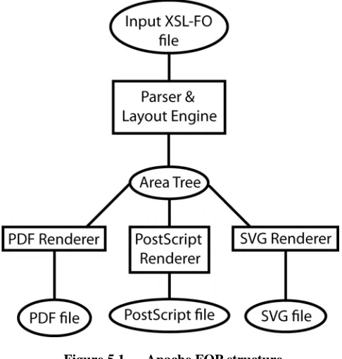
The design of Apache FOP is such that it is split into two halves – the front end dealing with the parsing of the input XSL-FO file and the back end dealing with generating the desired output format. This is illustrated in Figure 5.1.
This separation allows for a modular approach to document transformation since any number of back end renderers can be written to target different output formats.
In order to pass through the GSBI generated in earlier stages of the workflow, FOP’s front end requires modification to ensure that this new information is reflected in the Area Tree.
Each of the back-end code-generators included as part of Apache FOP walks over the area tree structure and generates the appropriate output format but, by default, FOP will generate PDF. Unfortunately, PDF is a monolithic Page Description Language (PDL) with its basic level of document granularity being no finer than a whole page. This presents a problem since using it as the target output format would result in there being no method of selecting individual components within the document, which is obviously necessary for any low-level component visualization tool (see section 6). However, if PDF documents are built from individual COGs on the page then these components can be identified and manipulated separately. Thus, to support component objects on the final-form page, the FOP’s PDF code-generator was modified so that it generated COG PDF as opposed to ‘normal’ PDF.
5.2.1. Layout
Modifications
The front end of Apache FOP takes an input XSL-FO file, parses it, lays out the various ‘areas’, and generates an intermediate Area Tree. Internally, FOP does not build a DOM representation of the XML document but rather creates its own data structures. This is advantageous since it is possible to extend these data structures to store the GSBI data. Unlike XSLT, it is not possible build a generic converter, and the modifications to the FOP source code must be made by hand.
Two changes were required to ensure that the Area Tree would contain all the required information for the back end PDF renderer. Firstly, the GSBI contained within the XSL-FO file needs to be copied across onto the relevant as they were created. FOP’s XML parsing routines needed to be modified to make them aware of the GSBI attributes contained within the XSL-FO source and to ensure they were parsed alongside the XSL-FO attributes.
Secondly, the GSBI data needs to be updated with information about the transformation that FOP itself is performing. The parser keeps track of its current position within the XSL-FO input, and can use this information to generate an XPath when needed. Therefore, when a new part of the Area Tree is created the current XPath (which represents the part of the XSL-FO input that has caused it to be created) can be fetched from the parser and stored alongside the GSBI already present within FOP’s internal data structures.
With the above changes made to the front end of FOP, all the required information is now stored in the Area Tree. However, as things stand, this information will be ignored by the default PDF code-generation engine in FOP and so would be unavailable in the final PDF output.
5.2.2. PDF Code Generation
[image:5.612.53.296.73.328.2]FOP’s default PDF code generator produces standard monolithic PDF documents and is not designed to preserve any segmentation of the document content that may be visible during earlier stages of the document workflow (including within FOP’s own internal data structures). Having made the decision to use COG technology for preserving this content segmentation in the final output, it was then necessary to modify the PDF code generator to produce COG-PDF output.
Figure 5.1 — Apache FOP structure
Initially, it was envisaged that a number of carefully implemented changes to the existing FOP PDF code generator would be sufficient to achieve the desired effect. However, after an initial inspection of the way the PDF code generator was constructed it became apparent that more extensive modifications would be required.
The structure of the Area Tree is such that the various areas are grouped into ‘blocks’, however there are a number of exceptions that are handled separately. As the PDF renderer descends the Area Tree, it renders these blocks by calling other methods to handle the various types of area. Since these blocks typically correspond to logical blocks in the content (paragraphs, headings etc) it was decided that this was a good place to ‘hijack’ the processing of the Area Tree in order to generate COG-PDF. In this way each input block would correspond to a COG in the output PDF. This strategy was implemented by setting up the new objects required for COG output, within the code generator, followed by a final output of the set of COGs as a PDF stream together with the resetting of the various state objects.
One of the major obstacles was the way in which the original FOP PDF code generator handled resources such as fonts. COGs are treated as self-contained components that do not affect the graphic state of the PDF because they contain references to all of their required resources. The default FOP implementation maintains a single list of resources that is shared among all pages in the document. Unfortunately this would ruin the self-contained nature of resources in the COG approach and so the resource handling within the PDF generator had to be modified so that a new resource list was generated every time a new COG was initialized and this list was then associated with the relevant COG.
page by accumulating the size of each block of output, plus any specified spacing. To correctly generate COGs with a local-origin, it is necessary to also keep track of the starting y-position for each block so that the co-ordinates can be generated relatively. Things are further complicated by XSL-FO’s origin being at the top-left while PDF uses the bottom-left, requiring further mathematical contortions to be performed to calculate the correct co-ordinates. Once, the COG has been generated a Spacer object is also inserted onto the current page to ensure that it is imaged at the correct point on the page [1].
6. VISUALIZATION
The result of the modified document workflow components is a COG-PDF file where each COG contains embedded GSBI detailing the precise transformations that were used to create it. Using this information, it is possible to write tools that allow the user to visualize the document workflow.
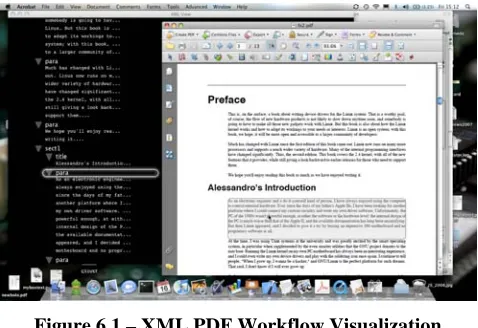
[image:6.612.55.294.330.494.2]The first visualization tool developed mimics the one developed by Hardy [10]. Here, the original XML source document is showed in tree form alongside, the PDF document. Figure 6.1 shows our implementation. The UI enables the user to see part of the PDF document with its source XML node highlighted, and vice versa, i.e. highlighting part of the XML tree and seeing which part of the PDF it generated.
Figure 6.1 – XML PDF Workflow Visualization
Implemented as an Acrobat plug-in, this visualization tool can be split into three components: the XML source document view, the PDF to XML mapping, and the XML to PDF mapping.
6.1. Source XML view
The original source file (the location is retrieved from the GSBI stored within the PDF) is parsed and used to create a modified DOM tree. The traditional DOM objects are extended using the decorator pattern [12] to contain pointers to the user interface objects that represent each node. This extra information is used later for efficient update of the UI whenever a COG is highlighted in the PDF section.
With the DOM built, the plug-in iterates over each node in the tree to build the user interface. The current implementation makes use of Apple’s CoreAnimation API in MacOS X 10.5 to provide a graphically rich front-end, however there is no reason why it could not be rewritten to use a different UI API.
With the relevant user interface objects built, the XML source view window can be opened on screen, awaiting user interaction.
6.2. PDF to XML highlighting
To update the XML view when the user highlights a COG requires the plug-in to be able to track the mouse location within the PDF window. Fortunately, the existing COG Manipulator
[1,13] tool could be modified, using the Observer pattern, to allow the Acrobat plug-in to be notified whenever a COG is selected. The visualization plug-in can then register itself with the modified COG Manipulator to receive notifications, when a COG is highlighted. Details of the highlighted COG are passed over as part of the notification.
When a COG is highlighted, the plug-in looks at the GSBI embedded inside the COG. This contains an XPath that points at the XML node that was eventually transformed into this piece of the document.
This XPath is used to traverse the DOM representation of the source XML document. The decorated DOMElement object at the other end of this XPath contains a pointer to the user interface component that represents this node and we can then update the XML window to display this node.
6.3. XML to PDF highlighting
At first glance, the implementation of the reverse side of the visualizer, i.e. letting users click on the XML nodes to update the PDF view seems simple. However, it soon becomes clear that the problem is more involved than is first apparent.
Firstly, the source nodes are, obviously, not tagged with details of COGs that they generated. This in itself is not a problem because it is simple enough to iterate over all the COGs in the PDF, and to fill in the identifiers for each COG within the decorated nodes in the DOM. However, this information alone is not enough because the COGs have no idea whereabouts in the document they are to be rendered and so it is necessary to include extra details concerning which page the COG is to be drawn on. The result is that each of our decorated DOM objects contains details of the COG they produced as well as the UI objects that draw them.
While there is usually a one-to-one mapping of COGs to source XML nodes, the opposite is not true. For example, more than one COG may be generated if some logical text block happens to split over a page or column break. And this is not the only circumstance that can cause a single XML source node to generate more than one COG; an obvious further example would be the generation of a Table of Contents. Here, the section headings not only generate COGs during the normal flow of the document, but they also generate a second COG at the beginning of the document representing the accumulated table of contents.
This occasional lack of one-to-one correspondence does not complicate the programmatic operation of the plugin; it simply builds up a collection of generated COGs, rather than just a single COG, when iterating over the document. However, it does complicate the user interface and poses the question of how the user should be presented with the fact that two or more COGs have been generated for some given single XML node.
question is how to determine programmatically which COG that is. One method that is currently being tested is too look at the location of the nodes before and after the node in a depth-first search of the tree and to chose the location that is closest to them.
It should also be noted that some XML source nodes do not generate any COGs at all. An example of this would be a tag that denotes that some text should be emphasised (e.g. by emboldening or italicizing it). This node would be subsumed into its parent node’s COG. If these nodes are selected in the XML source tree, then the plug-in highlights the COG associated with its parent node.
6.4. Extended Visualization
As it stands, the current visualization tool, built on a document component approach, might seem to be offering a very similar display to the structural-tree-based viewer described in previous work [10]. However, the underlying tagging and component technologies of the present work enable us to develop more powerful tools for extending the visualization experience. The following sub-sections set out some of the possibilities.
6.4.1. Displaying leaf-node material
At present the XML source view displays only XML element nodes; it makes no attempt to display the text-containing leaf nodes. However, since COGs can be drawn independently of each other (and of the page on which there are drawn) there is nothing to stop us inserting the final COGs into the XML tree view as the first child of the nodes that generate them. Work is currently underway to add this feature to the visualizer.
6.4.2. Full Workflow visualization
Currently, only the source form and final form documents are shown in the visualization, but it would be relatively straightforward to show all the intermediate stages (assuming that the appropriate intermediate files are kept on the system and have not been deleted). In this case, multiple XML windows would be displayed on screen, one for each XML document. Then as the user moves around any of the documents, the other views would be updated synchronously.
6.4.3. Transformation
Visualization
Another useful view that could be provided is one that to show all the transformations that were undergone to create a particular piece of the final output. Here, working backwards from the right, the user would see the sections of the XSLT transformations that produced the given COG together with the input to that part of the transformational chain (all reduced down to a view which shows only the nodes involved). Then, to the left of this, would be the transformations that produced this final stage — and so on, until the relevant nodes in the initial source document are located.
This approach could be very useful as a debugging tool for finding errors in a document workflow, because the user would be able to see exactly which transformations were being used at every stage.
6.4.4. Handling one-to-many relationships
We have already pointed out that a node in the initial source document might produce more than one COG in the final PDF. Work needs to be carried out to develop a method of illustrating this one-to-many relationship to the user.7. CONCLUSIONS AND FUTURE WORK
Throughout this paper the tagging information calculated and stored in the various stages of the document workflow refers back to particular nodes in the input, and in the intermediate XML files, as well as to specific filenames. This is a potential source of problems when modifications are made to the source documentafter the final output file has been produced, since the XPath references in the final PDF may no longer be accurate. A simple method of solving the problem is to generate and store a hash of the source file, along with all the other information, and to check this hash when referring to the file in any way. However, there is now much research being conducted into versioning of XML files[14] and in the long run this may lead us to a more suitable and elegant solution.
As discussed in section 4, the tools developed to modify the DocBookXSL scripts are capable of modifying any XSLT script that takes XML-based markup as its input and produces XML as output. Therefore, an obvious extension to our work is to verify that our tools and techniques truly do work on XML-based source document types other than DocBook and also to find a way of supporting non-XML input. A possible way of tackling this latter problem is via IML[15] which has processors for a variety of non-XML inputs that generate a common non-XML format which could then be processed by our existing tools. Indeed, this present work grew out of collaborations with the authors of IML at the University of Bologna and further collaboration is envisaged.
We have already described an immediate use for our tools and techniques in debugging document workflows and this leads on very naturally to the quality checking of final PDF output, provided it has been produced in COG form. If some ‘rogue’ element appears (or if some desired element fails to appear) then an audit trail can be established for tracing how the desired content was generated (or how it failed to be generated). We also see a potential for using our annotators and visualizers as an aid to teaching generalised XSLT transformations, and document workflow techniques, to undergraduates.
8. ACKNOWLEDGMENTS
Thanks are due to Hewlett-Packard Labs (UK) and EPSRC for supporting James Ollis’s PhD studentship.
9. REFERENCES
[1] Steven Bagley, David Brailsford, and Matthew Hardy, “Creating reusable well-structured PDF as a sequence of Component Object Graphic (COG) elements” in
Proceedings of the ACM Symposium on Document Engineering (DocEng’03), pp. 58–67, ACM Press, 20–22 November 2003, Grenoble, France.
[2] John Lumley, Roger Gimson and Owen Rees, “A Framework for Structure Layout and Function in Documents,” in
Proceedings of the ACM Symposium on Document Engineering (DocEng’07), pp. 58–67, ACM Press, 20–22 November 2003, Grenoble, France.
[3] DocBook Technical Committee DocBook Schema Specification, http://www.docbook.org/schemas/5x. 2008
[5] Apache FOP (Formatted Objects Processor) 2008
http://xmlgraphics.apache.org/fop/
[6] Michael J. Eager. Introduction to the DWARF debugging format February 2007. http://dwarfstd.org/Debugging using DWARF.pdf
[7] DocBookXSL Stylesheets, 2008
http://docbook.sourceforge.net/
[8] Michael Kay, Saxon XSLT Processor. http://saxon.sourceforge.net
[9] Adobe Systems Inc, PDF Reference (Third Edition; PDF 1.4), Addison Wesley.
[10] Matthew Hardy and David Brailsford, “Mapping and Displaying Structural Transformations between XML and PDF” in Proceedings of the ACM Symposium on Document Engineering (DocEng’02), pp. 95–102, ACM Press, 8–9 November 2002, McLean Virginia, USA.
[11] Matthew Hardy, “The Mars Project — PDF in XML” in
Proceedings of the ACM Symposium on Document
Engineering (DocEng’07), pp. 161–170, ACM Press, 28–31 August 2007, Winnipeg, Manitoba, Canada.
[12] Erich Gamma et al, “Design Patterns: Elements of Reusable Object-Oriented Software”, Addison-Wesley 1995. ISBN:0-201-63361-1
[13] Steven Bagley and David Brailsford, “The COG Scrapbook” in Proceedings of the ACM Symposium on Document Engineering (DocEng’05), p. 31, ACM Press, 2–4 November 2005, Bristol, UK.
[14] S. Y. Chien, V. J. Tsotras and C. Zanolio. “XML document versioning”. SIGMOD Rec. 30, 46–53. Sept. 2001