ISSN Online: 2333-9721 ISSN Print: 2333-9705
DOI: 10.4236/oalib.1105279 Mar. 20, 2019 1 Open Access Library Journal
Geometric Accuracy Design Method of Roller
Cavity Surfaces for Net-Shape Rolling
Compressor Blades
Qichao Jin
1,2*, Wenhu Wang
2, Ruisong Jiang
2, Zongyan Cai
1, Datao Li
11Key Laboratory of Road Construction Technology and Equipment of MOE, Chang’an University, Xi’an, China
2The Key Laboratory of Contemporary Design and Integrated Manufacturing Technology, Ministry of Education, Northwestern
Polytechnical University, Xi’an, China
Abstract
The accurate shape of roller cavity surfaces is vital part for net-shape rolling. This paper presents a new design method of roller cavity surfaces with high accuracy for rolling compressor blades based on the geometrical inheritance and evolution of the net-shape profiles. Firstly, a process model of the blade is modeled by adding process allowance and locating basis at the CAD (Com-puter Aided Design) model of the blade to represent the roll formed blade, the process model inherits the net-shape profiles of the blade at the pressure and suction surfaces. Secondly, an algorithm is proposed to discretize a curve to a set of ranked points with the restriction of the maximum chord height, and a new section curve which represents the geometrical feature of the pres-sure and suction surfaces are distributed on the process model based on the algorithm. Finally, a mapping algorithm is proposed to transform the section curves to the cavity section curves around the roller axis based on the conju-gate movement between rollers and blade, and the cavity surfaces are recon-structed based on the transformed section curves. The design method is im-plemented for the roller cavities of a variable cross-section compressor blade, and the accuracy of the designed cavities is checked based on the precision of the roll formed blade by the finite element method. The results reveal that the designed cavities achieved the net-shape precision at pressure and suction surfaces of the blade. The paper provides an effective method for designing rolling cavity surfaces with excellent design quality.
Subject Areas
Aerospace Engineering, Mechanical Engineering How to cite this paper: Jin, Q.C., Wang,
W.H., Jiang, R.S., Cai, Z.Y. and Li, D.T. (2019) Geometric Accuracy Design Method of Roller Cavity Surfaces for Net-Shape Rolling Compressor Blades. Open Access Library Journal, 6: e5279.
https://doi.org/10.4236/oalib.1105279
Received: February 21, 2019 Accepted: March 17, 2019 Published: March 20, 2019
Copyright © 2019 by author(s) and Open Access Library Inc.
This work is licensed under the Creative Commons Attribution International License (CC BY 4.0).
http://creativecommons.org/licenses/by/4.0/
DOI: 10.4236/oalib.1105279 2 Open Access Library Journal
Keywords
Rollingblade, Cavity Design, Process Model, Section Curves, Discretizing Algorithm, Transformation Algorithm
1. Introduction
Rollforming is one kind of important machining method of high compressor blade, due to the characteristics of the rolling blade with large quantity, thin thickness, and high precision requirement. In a blade rolling process, a blank is rolled between a pair of rotated rollers with a shaped surface and produced plas-tic deformation. With the cross sectional shape being progressively decreasing, a blade is printed along the rolling direction at the outlet. In order to meet the high precision required by manufacture and good uniformity demanded by as-sembly, an accurate shape of rolling cavity is necessary for blade rolling.
DOI: 10.4236/oalib.1105279 3 Open Access Library Journal the precision design of rolling dies was presented based on the conjugate prin-ciple. All of those works were based on given die or roller profile which could be described by a formula. Indeed, few work focus on designing a roller cavity for rolling a complex component with varying cross section.
The conjugate movement between rollers and component is fundamental for designing roller cavity. Cai [15] stated that cavity design for rolling process is a sophisticated task due to the complex relative motion between dies and the plas-tic deformation of the roll-forging pieces. Zhang et al.[16] investigated the mo-tion characteristic between the die and the workblank under varied center dis-tance in rolling spline. According to the kinematic relation of the rolling process, the roller cavity design is different from the cavity design for casting, which is almost a copy of the component’s profile. The rolling cavity is a varied and semi-closed gap between a pair of rotated roller, and cavity surfaces are en-wound from component’s profiles. Zhao et al. [17] designed the arc length of groove of roller based on predicted forward slip value for rolling a revolving component with changeable thickness. Most of the roller for rolling complex components is achieved by trial and error. It prolongs the setting time, and can-not meet the requirement of high manufacturing accuracy either. In a rolling process, the blank deforms continuously within an open gap, which is shaped by a pair of rotating rollers. The blank is squeezed and experienced plastic deforma-tion, and the excrescent material, i.e. overflow, is generated at two sides of the roller gap. The blank is rolling formed to an expanded shape of the blade after the blade rolling process. In order to characterize the expanded shape, the origi-nal blade CAD model is inlaid into the expanded model, which is named as the process model of blade. Hence, design the process model based on the CAD model of the blade is the first step for designing roller cavity. Then, the pressure and suction surfaces of the process model are mapped to cavity surfaces based on a transforming algorithm. Chan et al. [18] proposed a new fitness function for family mould layout design optimization, and considered the accurate re-quirement.
In order to design the roller with acceptable accurate requirement for a com-plex part, it is vital for transforming the profile of the rolled part to the cavity surfaces of the rollers. In this paper, a numerical design method for blade rolling cavity surfaces is studied with geometric inheritance of the blade’s profiles. The rolling cavity design process is demonstrated for a high compressor blade with varying cross-section, and the simulative method are implemented to estimate the designed cavities. The results show that the rolling formed blade achieved net-shape at pressure and suction surface when using the designed roller. The proposed design method of roller cavity surfaces surmounts traditional method which based on trial and error, and shortens the setting period of roller with a high design precision.
2. Outline of the Cavity Surface Design Method
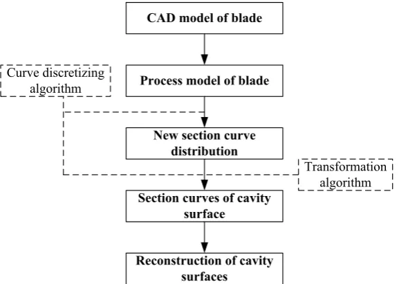
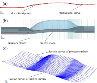
DOI: 10.4236/oalib.1105279 4 Open Access Library Journal part based on geometrical inheritance and evolution, and the geometrical inhe-ritance and evolution accuracy of the part is emphasized. A stator blade model of compressor is used to illustrate the design method of the rolling cavity surface. The original cross section curves of the blade and CAD model of the blade are showed in Figure 1(a) and Figure 1(b) respectively. The flowchart of the design method is presented in Figure 2. Firstly, a process model is designed by inherit-ing the profiles from the CAD model of blade. Secondly, a new section curve distribution is created on the process model based on a discretizing algorithm which is also used in following parts, and the new section curves should represent the geometrical characteristics of the process model. Finally, the section curves are transformed to the section curves of the cavity surface based on a transfor-mation algorithm, the transforming accuracy of the corresponding section curves are assured by the discretizing algorithm. The rolling cavity surfaces are created
Figure 1. CAD models of a representative compressor blade and its corresponding roller: (a) Original cross section curves of the blade; (b) Overview of the compressor blade; (c) Overview of the roller for the rolling blade.
Figure 2. Flowchart of the design method for the rolling cavities.
(a) (b) (c)
CAD model of blade
Process model of blade
Section curves of cavity surface
Reconstruction of cavity surfaces New section curve
distribution Curve discretizing
algorithm
[image:4.595.230.519.499.704.2]DOI: 10.4236/oalib.1105279 5 Open Access Library Journal based on the transformed section curves and the rolling dies are created based on designed cavity surfaces. The designed roller for the blade is showed in Fig-ure 1(c).
3. Details of the Roller Cavity Surface Design Method
According to the flowchart of the method to design the rolling cavities for pro-ducing compressor blades, the development of the process model, the creation of the section curves of the process model, and the creation of section curves of the cavity are discussed below in details.
3.1. Development of Process Model
The process model is an imaginary model based on the CAD model of the blade to describe the shape of the blade blank after rolling process. It inherits and de-velops the geometrical characteristic of the pressure and suction surface of the blade, and intermediates the original blade model to the rolling cavity model. The process model is represented by its cross section curves, which are evolved from the section curves of the original CAD model of blade. The overflow boundaries at the leading and trailing edges are added to the suture pressure and suction surface. The machining allowances are added by extrapolating the root and top section curves of the blade to ensure integrity of the blade profiles. A location block is also appended at the root section of process model for holding and positioning in manufacturing process. The process model evolves from the original blade CAD model, and it seems like that the compressor blade inlaid in the process model. The procedure of developing process model is presented as followed.
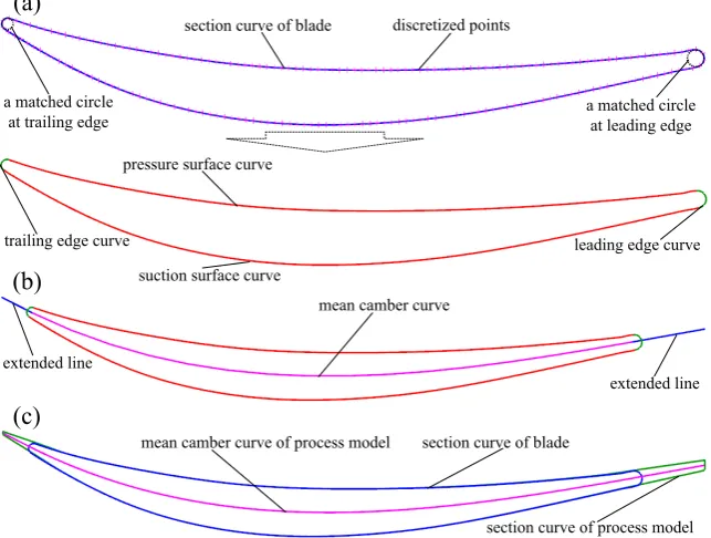
DOI: 10.4236/oalib.1105279 6 Open Access Library Journal Figure 3. Constructing a typical cross section of a process model from the cross section of the original CAD model of the blade. (a) Section curve of the blade with discretized points. (b) Mean camber curve of the blade section curve. (c) Section curve and mean camber curve of the process model.
lines and the mean camber curve of the blade, see Figure 3(c). The two end-points on the mean camber curve of processor model are offset to two sides as relevant radius of leading and trailing edges. The offset points are connected and smoothed to the pressure surface curve and suction surface curve, and the smoothed curves are the section curves of the process model. The original tion curve, mean camber curve and section curve of a representative cross sec-tion of the process model are showed in Figure 3(c). After adding the overflow boundaries on every theoretical cross section of the blade, a CAD model which represents the shape of the blade after rolling is structured through the closed section curves of the process model sequentially.
3.1.2. Addition of Auxiliary Units
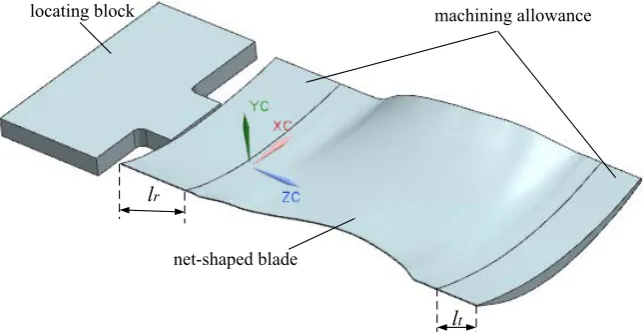
A wire electrode cutting process will be used to separate the blade from the roll-ing formed blade at root and tip sections after machinroll-ing arcs, which suture the pressure and suction surfaces at the leading and trailing edges. Hence, the ma-chining allowances are added at the root and the tip of blade, see Figure 4. The addition of the machining allowances can also reduce the impact load on the cavity at the beginning and the end of the rolling process. The tip section curve of blade is stretched outwards by a length of lt to set up the tip machining al-lowance, and root section curve of blade is stretched outwards by a length of lr to set up the root machining allowance, see Figure 4. An integrated process model for rolling blade also needs a location block for holding the blade in the entire
(a)
section curve of blade discretized points
a matched circle at leading edge a matched circle
at trailing edge
trailing edge curve
pressure surface curve
suction surface curve
leading edge curve
(b)
mean camber curve
extended line extended line
section curve of blade
section curve of process model mean camber curve of process model
DOI: 10.4236/oalib.1105279 7 Open Access Library Journal Figure 4. A complete process model constructed from the original blade model.
manufacturing process. This block is used as a locating device which is con-nected with the blade by a plate. Coordinate systems are needed in parameter design of blade rolling cavities. Because the thickness of the root section is bigger than the tip’s thickness, rolling direction is chosen from tip to root of blade. The center point of the maximum inscribed circle at root section is set as original coordinate for modeling coordinate system. Z axis is a vector from blade root to tip, X axis is a vector from trailing edge curve center point to leading edge curve center point, and Y axis is determined by following the right hand rule in the Cartesian coordinate system. The complete blade process model is showed in Figure 4.
3.2. Creating Section Curves Using a Discretization Algorithm
The CAD model of blade is sketched by sequential cross section curves at dif-ferent locations from the blade root, i.e., stacking height, and the manufacturing accuracy is estimated by comparing the cross section curve of rolling formed blade with the original section curve of CAD model. Designing rolling cavity surfaces is to convert the blade profiles to roller cavity around their axes. It is a coordinate transformation for spatial surfaces. Generally, a 3-dimensional pro-file is discretized to a set of points. These points are transformed to new points by mapping their coordinate. After that, a new surface is reconstructed based on the new set of points, see e.g. Ali et al. [19] Considering the original CAD blade model is sketched by ranked section curves which are tested and designed by wind tunnel experiment, see Figure 2(a), it is an efficient method to design rolling cavities by mapping the ranked section curves of the process model (in-stead of its entire surface) to the section curves of cavities. The mapping trans-formation of the original section curves of the process model is insufficient due to the deviation of curve approximation. Increase the number of section and distribute them reasonably is an efficient method to improve design accuracy of roller. In order to distribute section curves on the profiles of process model, an orientational curve is sketched along the maximum inscribed circle’s center pointnet-shaped blade
machining allowance locating block
l
tDOI: 10.4236/oalib.1105279 8 Open Access Library Journal of original section curves at different stacking height sequentially. The center point of the biggest inscribed circle is a unique point for every section curve, and it locates section curve on cross section. A discretizing algorithm is proposed by limiting the maximum chord height to segment a curve to a set of ranked point. The cross sections are created at the discretized points along the orientational curve. The section curves of the process model are generated as the intersection curves of the blade profile and the cross sections.
3.2.1. Determining the Location of the Section Curves
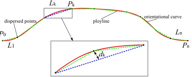
A curve can be discretized into points using different methods, such as the length restriction of segmented units, the restriction of chord height, and the re-striction of angle, etc. In order to use less number of points to represent a smooth curve with required accuracy, a discretizing method is proposed by limiting the chord height of the discretized units. The threshold value is related to the re-quirement of the blade tolerance. The chord height is the largest distance from the bow to the line between start and end point in each unit. If the chord height is smaller than the threshold value, the curve can be simplified to the line. Oth-erwise, a new point is inserted on the curve at the farthest point from the line. Then, the new units are checked by limiting the chord height again until every discretized unit meets the limitation of the threshold value. In the case illustrated in the inset of Figure 5, if dk ≤δ , then the straight green line is used to replace
the original red curve; if dk >δ , the straight blue line can’t replace the original
red curve, then a new point is added and the two straight green lines are used to replace the original red curve. The curve is discretized into the ranked points based on the required threshold value. The diagram of discretizing process is showed in Figure 5. k is the serial number of discretized curves and retuned points, Pk is the serial number of discretized points, Lk is the serial number
of broken lines, and dk is the height of the chord. In this way, the red curve is
[image:8.595.213.537.561.691.2]discretized into the green polyline based on the discretizing algorithm, and the discretized points are used to represent the orientational curve. These discretized points of the orientational curve are the locations to create the section curves of the process model.
Figure 5. Discretizing the blade orientational curve under the constraint of the chord height.
orientational curve ployline
dispersed points
d
kL
1L
kL
nP
kP
0DOI: 10.4236/oalib.1105279 9 Open Access Library Journal 3.2.2. Creating Section Curves of the Process Model
The orientational curve of blade describes rotation and translation of the pres-sure and suction surface along the stacking direction. The orientational curve is discretized into a ranked point set by limiting chord height as discussed in Sec-tion 3.2.1, see Figure 6(a). The distribution of cross sections is created by in-serting planes vertical to Z-axis at the locations of the ranked points, see Figure 6(b). New section curves are the intersection curves of the auxiliary planes and the profiles of the process model, see Figure 6(c).
3.3. Creating Section Curves of Roller Cavity through Coordinate
Mapping
[image:9.595.213.536.391.665.2]The final step to design the roller cavity is to revolve the updated section curves of the process model to the section curves of the cavity surfaces. According to the coordinate systems presented in Section 3.1.2, the corresponding coordinates of the points of the cavity section curve are mapped from the new section curves. The springback compensation was implemented to achieve net-shape of the cross sections and forward slip compensation was implemented to calculate the mapping angle of the sections [20]. In order to achieve the coordinate transfor-mation, the updated section curves of process model are discretized into point sets. The number and distribution of the discretized points on the section curve also have an important effect on the precision of the section curve of cavity surface.
Figure 6. Creation of cross section curves of the process model based on the discretized points on the orientional curve. (a) The orientional curve and discretized points. (b) The auxiliary planes and the process model. (c) A new set of section curves of the process model.
auxiliary planes process model
(a)
(b)
discretized points orientational curve
(c)
Section curves of pressure surface
DOI: 10.4236/oalib.1105279 10 Open Access Library Journal The updated section curves are discretized into ranked points used the discre-tizing algorithm presented in Section 3.2.1. The coordinates of the ranked point set are rotated around the roller axis and generated the corresponding ranked point set which represents the section curve of cavity. The distance between the top roller’s axis and the bottom roller’s axis is D. The coordinate mapping algo-rithm for the top and the bottom roller cavity surfaces are presented in Equation (1) and Equation (2), respectively,
( )
( )
cos 2 2 sin 2 k k x x D D y y D z y θ θ ′ = ′ = − − ′ = − (1)
(
)
(
)
cos 2 2 sin 2 k k x x D D y y D z y θ θ ′ = ′ = − − − − ′ = − − (2)
where
(
x y z)
is the discretized point’s coordinates of the updated section curve,(
x y z′ ′ ′)
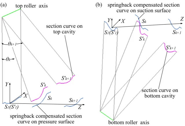
is the point coordinates of the section curve of the cavity surfaces, θk is the rotational angle. [image:10.595.214.534.462.680.2]A new point set which represents the section curve of cavity surface is created based on the mapping algorithm. The cavity section curves are reconstructed through the new point sets. The mapping process of the section curves of the top and bottom cavity surface is shown in Figure 7. The blue curves Sk are section
Figure 7. Illustration of mapping transformation for section curves: (a) Mapping section curves from the pressure surface to top mold cavity; (b) Mapping section curves from the suction surface to bottom mold cavity.
θk+1
θk
S1(S'1)
S'k Sk S'k+1 Sk+1 Z X Y
top roller axis (a) X Y Z S'k Sk S'k+1 Sk+1
bottom roller axis
S1(S'1)
(b)
springback compensated section curve on pressure surface
springback compensated section curve on suction surface
section curve on top cavity
DOI: 10.4236/oalib.1105279 11 Open Access Library Journal curves of process model which are created in Section 3.3.2. The red curves Sk′
are ranked section curves of cavity surfaces. The section curves of the processes model and cavity surface are the same at the exit section (θ =0 0), see Figure 7.
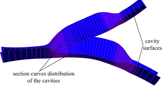
The designed cavity surfaces are reconstructed based on the mapped section curves, as showed in Figure 8. The rollers for rolling compressor blade a re-created based on the design cavity surfaces.
4. A Case Study to Validate the New Design Method
In order to validate the new design method, the FEM simulation were carried out to form a rolled blade, and four groups of corresponding section curves at the different stacking height are investigated.
4.1. A Case Study to Design Cavity Surfaces for a High Pressure
Compressor Blade
A high-pressure compressor statorblade (Figure 1(b)) of an aero-engine is formed by rolling. The total stacking height of the blade is 38 mm, and the ma-chining tolerance is ±0.02 mm. The new design method was used to create the roller cavity surface for the blade. Firstly, a process model of the blade was de-veloped based on the CAD model of the blade. The overflow were added on the original section curves of the blade, see Section 3.1.1. The auxiliary units were added to achieve the process model, see Section 3.1.2. In order to add the ma-chining allowances at the root and the tip of blade, the tip mama-chining allowance
t
l was 6 mm and the root machining allowance lr was 10 mm, see Figure 4.
[image:11.595.236.514.557.704.2]Secondly, a new section curves distribution was created on the process model, see Section 3.2. An orientational curve was sketched along the maximum in-scribed circle’s center point of original section curves at different stacking height sequentially. The orientational curve was discretized into a ranked points which determining the location of the section curves. The new cross section is created by inserting planes vertical to Z-axis at the locations of the ranked points and the new section curves are the intersection curves of the auxiliary planes and the profiles of the process model, see Figure 6. Thirdly, the section curves of cavity
Figure 8. Reconstruction of the cavity surfaces based on the section curves of the cavity. cavity surfaces
DOI: 10.4236/oalib.1105279 12 Open Access Library Journal surface were transformed from the section curves based on the mapping algo-rithm, see Section 3.3. The distance between the top roller’s axis and the bottom roller’s axis is 136 mm which discussed in Equation (1) and Equation (2). The cavity surfaces were reconstructed based on the mapped section curves of the cavity, see Figure 8. Finally, the contour surfaces of the roller were created based on the designed cavity surface, see Figure 9(a). In order to create a pair of solid roller, a pair of fan-shaped bodies was separated by the contour surfaces, see Figure 9(b). The solid roller is showed in Figure 1(c).
4.2. FEM Code for Blade Rolling Process
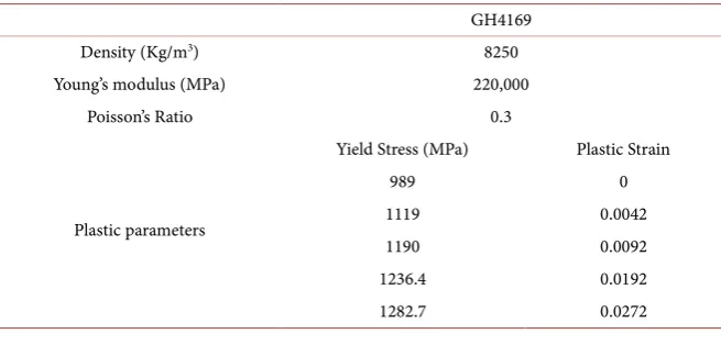
[image:12.595.210.538.575.732.2]A simulation model was created for the blade rolling process. The rolling process was replicated in the numerical simulation using a non-linear Explicit FE code (ABAQUS/Explicit 6.14-1). The reduced integration, hourglass control (C3D8I) is used to mesh the blank, and the mesh size is 0.1 mm. The blank is a flat plate and the thickness reduction is 30%. The properties of the blank are showed in Table 1. The bilinear, rigid, quadrilateral element control (R3D4) is used to mesh the dies, and the size of mesh is 0.1 mm. The top and bottom rollers are rotated with the angle velocity of 0.5 rad/s. The interactions between the blank and roller surface are defined using the default “master-slave” algorithm. To si-mulate the oil lubrication, the interface friction coefficient is set as 0.25. The model of rolling simulation is showed in Figure 10(a), and the rolling formed blade is showed in Figure 10(b).
4.3. Results and Discussion
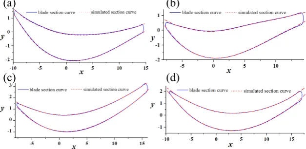
The precision of profile of the produced blade is evaluated by its section curves [21]. The root and tip section curves (0 mm and 38 mm) are boundaries of the blade for assembly. The section curves of the blade are severely rotated and translated at the stacking height of 8 mm and 32 mm. Hence, the cross section curves of the rolling formed blade and the simulation result at the stacking height of 0 mm, 8 mm, 32 mm, 38 mm are measured and sketched. Those sec-tion curves are compared with the original secsec-tion curves of CAD model. The section outlines are showed in Figure 11.
Table 1. Material parameters of GH4169 at room temperature. GH4169
Density (Kg/m3) 8250
Young’s modulus (MPa) 220,000
Poisson’s Ratio 0.3
Plastic parameters
Yield Stress (MPa) Plastic Strain
989 0
1119 0.0042
1190 0.0092
1236.4 0.0192
DOI: 10.4236/oalib.1105279 13 Open Access Library Journal Figure 9. Illustration of a fully designed rollers based on the designed cavity surfaces: (a) The contour surfaces of the rollers; (b) Separation of the solid rollers from fan-shaped bodies by the contour surfaces.
Figure 10. The validation of the designed cavity surface by the FEM simulation. (a) The FEM model for rolling simulation, (b) The rolling formed blade from the FEM simula-tion.
Figure 11. Comparison of section curves from the original CAD model of blade, FEM simulation at different stack height: (a) Z = 0 mm; (b) Z = 8 mm; (c) Z = 32 mm; (d) Z = 38 mm.
The section curves from FEM simulation are compared with the original sec-tion curves on CAD model at the same stacking height. The results demonstrate that the section curves from simulation have a good consistency with the CAD model. The largest error of every section curves is smaller than the required to-lerance (0.02 mm) of the blade. The results reveal that the designed cavities meet
designed
cavity surfaces fan-shaped bodies
(b) (a)
(a)
(b)
[image:13.595.217.531.439.592.2]DOI: 10.4236/oalib.1105279 14 Open Access Library Journal the precision of net shape at the pressure and suction surfaces of the blade. The design method is suitable for designing the roller cavity surface for the com-pressor blade.
5. Conclusions
A new design method of cavity surfaces for rolling compressor blades is pro-posed for complex part based on geometrical inheritance and evolution, and the geometrical inheritance and evolution accuracy of the part are emphasized. The design procedure and algorithm are discussed in detail. The major works are summarized below.
The new cavity surface design method for net shape rolling blade is proposed based on the motion relation and geometrical inheritance. A process model between the blade and the cavity surface is introduced in design process to represent the pressure and suction surface of the blade before transformation. An algorithm is used to discretizea curve to a set of ranked points with the
restriction of the maximum chord height. The discretizing algorithm con-nects the discretizing precision with the design tolerance of a blade. It is an effective method to improve design accuracy under a tolerance requirement. A mapping algorithm is presented for designing a compressor blade rolling
cavity surfaces. The coordinate transformation formula from the updated section curves to the section curves of cavity surfaces is derived based on the conjugate movement between the rollers and blank.
A case study is implemented based on the new design method to design a pair of rollers for rolling a compressor blade. The numerical simulation was used to evaluate the precision of the designed cavities. The results indicated that the formed blade satisfied with the tolerance requirement of blade. The proposed method is suitable for designing roller cavity surfaces.
Acknowledgements
This work was supported by National Natural Science Foundation of China (No.51475374), the Fundamental Research Funds for the Central Universities (No.3102015ZY087) and China Scholarship Council.
Author Contributions
Qichao Jin designed, conducted the research and wrote the paper. Wenhu Wang and Ruisong Jiang improved the design method and developed the program. Zongyan Cai and Datao Li discussed the research and editing the paper.
Conflicts of Interest
The authors declare no conflict of interest.
References
DOI: 10.4236/oalib.1105279 15 Open Access Library Journal on Edge Cracking in Cold Rolling. Materials and Manufacturing Processes, 30, 1174-1178. https://doi.org/10.1080/10426914.2013.811746
[2] Byon, S.M. and Lee, Y. (2014) An Investigation on the Effect of Design Parameters of Side Guide on Camber in Hot Slab Rolling. Materials and Manufacturing Processes, 29, 107-114. https://doi.org/10.1080/10426914.2013.811743
[3] Dong, Y.G. and Song, J.F. (2016) Research on the Characteristics of Forward Slip and Backward Slip in Alloyed Bar Rolling by the Round-Oval-Round Pass Se-quence. The International Journal of Advanced Manufacturing Technology, 87, 3605-3617. https://doi.org/10.1007/s00170-016-8731-0
[4] Kong, N., Cao, J.G., Wang, Y.P., et al. (2014) Development of Smart Contact Back-up Rolls in Ultra-Wide Stainless Strip Rolling Process. Materials and Manufacturing Processes, 29, 129-133. https://doi.org/10.1080/10426914.2013.822979
[5] Zhang, J., Guan, R.G., Tie, D., Wang, X., Guan, X.H., et al. (2015) Effects of Tech-nical Parameters of Semi-Solid Stirring and Rheo-Rolling on Microstructure of A356-5wt.% B4C Composite Strip. Materials and Manufacturing Processes, 30, 340-345. https://doi.org/10.1080/10426914.2014.941477
[6] Su, X. and Xu, G.M. (2015) Microstructure Homogenization of 7075 Alloy by a Novel Electric Pulse Rheo-Rolling Process. Materials and Manufacturing Processes, 30, 1-5. https://doi.org/10.1080/10426914.2014.984204
[7] Sedighi, M. and Mahmoodi, M. (2012) Pressure Distribution in Cold Rolling of Turbo-Engine Thin Compressor Blades. Materials and Manufacturing Processes, 27, 401-405. https://doi.org/10.1080/10426914.2011.560229
[8] Sedighi, M. and Mahmoodi, M. (2009) An Approach to Simulate Cold Roll-Forging of Turbo-Engine Thin Compressor Blade. Aircraft Engineering and Aerospace Technology, 81, 191-198. https://doi.org/10.1108/00022660910954682
[9] Lu, B., Ou, H., Armstrong, C.G. and Rennie, A. (2009) 3D Die Shape Optimisation for Net-Shape Forging of Aerofoil Blades. Materials & Design, 30, 2490-2500.
https://doi.org/10.1016/j.matdes.2008.10.007
[10] Sung, J.U., Na, D.H. and Lee, Y. (2014) A Study on Design Equation of Separating and Oval Roll Grooves in Rebar Manufacturing Process. Materials and Manufac-turing Processes, 29, 100-106. https://doi.org/10.1080/10426914.2013.811742
[11] Ou, H., Lan, J., Armstrong, C.G., et al. (2004) An FE Simulation and Optimisation Approach for the Forging of Aeroengine Components. Journal of Materials Processing Technology, 151, 208-216.
https://doi.org/10.1016/j.jmatprotec.2004.04.042
[12] Ma, J. and Zhang, W. (2008) A Technical Note on Profile Curves Design of Tooth-Shaped Rolls. Journal of Materials Processing Technology, 204, 508-512.
https://doi.org/10.1016/j.jmatprotec.2008.01.051
[13] Kiuchi, M., Naeini, H.M. and Shintani, K. (2001) Computer Aided Design of Rolls for Reshaping Processes from Round Pipes to “Channel-Type” Pipes. Journal of Materials Processing Technology, 111, 193-197.
https://doi.org/10.1016/S0924-0136(01)00511-8
[14] Li, R.J., Li, M.Z., Qiu, N.J., et al. (2014) Surface Flexible Rolling for Three-Dimensional Sheet Metal Parts. Journal of Materials Processing Technology, 214, 380-389.
https://doi.org/10.1016/j.jmatprotec.2013.09.008
[15] Cai, Z.Y. (2005) Precision Design of Roll-Forging Die and Its Application in the Forming of Automobile Front Axles. Journal of Materials Processing Technology, 168, 95-101.https://doi.org/10.1016/j.jmatprotec.2004.11.005
DOI: 10.4236/oalib.1105279 16 Open Access Library Journal Workpiece in Spline Rolling Process with Round Dies. Advances in Mechanical En-gineering, 8, 1-12.https://doi.org/10.1177/1687814016655961
[17] Zhao, X., Zhang, Z.M. and Xue, Y. (2016) An Optimum Design on Rollers Con-taining the Groove with Changeable Inner Diameter Based on Response Surface Methodology. Advances in Mechanical Engineering, 8, 1-9.
https://doi.org/10.1177/1687814016651796
[18] Chan, I.W., Pinfold, M., Kwong, C.K., et al. (2014) Automation and Optimisation of Family Mould Cavity and Runner Layout Design (FMCRLD) Using Genetic Algo-rithms and Mould Layout Design Grammars. Computer-Aided Design, 47, 118-133.
https://doi.org/10.1016/j.cad.2013.10.006
[19] Ali, A.T., Aziz, H.A. and Sorour, A.H. (2015) On Curvatures and Points of the Translation Surfaces in Euclidean 3-Space. Journal of the Egyptian Mathematical Society, 23, 167-172.https://doi.org/10.1016/j.joems.2014.02.007
[20] Jin, Q.C., Wang, W.H., Yan, W.Y., et al. (2017) Springback and Forward Slip Com-pensation in Designing Roller Cavity Surfaces for Net-Shape Rolling Compressor Blades.https://doi.org/10.1080/10426914.2017.1317796