BOSD: Business Object Based Flexible Software
Development for Enterprises
Jindan Feng, Dechen Zhan, Lanshun Nie, Xiaofei Xu
Research Center of Intelligent Computing for Enterprises and Services, Harbin Institute of Technology, Harbin, China. Email: [email protected], {dechen, nls, xiaofei}@hit.edu.cn
Received July 15th, 2010; revised August 3rd, 2010; accepted August 15th, 2010.
ABSTRACT
The enterprise software need adapt to new requirements from the continuous change management. The recent devel-opment methods have increased the flexibility of software. However, previous studies have ignored the stability of
busi-ness object and the particular busibusi-ness relationships to support the software development. In this paper, a
coarse-grained business object based software development, BOSD, is presented to resolve this problem. By analyzing
the characteristics of variable requirement, business objects are abstracted as the separately-developed unit from
busi-ness process, and are assembled to system through their relationships. The methodology of BOSD is combined with
MDA (Model Driven Architecture) and implemented on the semiautomatic platform.
Keywords: Business Requirement Change, Business Object, Relationship, Business Process, Information Systems,
Flexibility, MDA
1. Introduction
Enterprises use information system to optimize their management, and further enhance its competitive abili-ties in the markets. There are many changes in the opti-mization processes, such as the transformation from ex-tensive management to inex-tensive management, the trans-formation from various objects to uniform business ob-ject, and the transformation from disordered process to normative process [1]. One of the major challenges in the enterprise software is the adaptability at run time.
Currently, there are basically two types of factors to flexible software development. The first factor includes the potential changes of requirements and the discipli-narian of these changes. The researchers consider that the software adaptabilities focus on the business processes [2,3], and the processes follow the special change pat-terns [4]. The second factor is the proper development approaches which support the disciplinarian. There are three representative approaches to achieve the flexible software: Component-Based Software Development (CBSD), Model Driven Development (MDD), and Ser-vice-oriented Software Development (SOSD).
The CBSD emphasizes the software architecture, on which the software is iteratively assembled with different grained components [5]. The software developed by
defines the sequence of Web Services Description Lan-guage (WSDL) interface, provides support for executable and abstract business process. Hence, the web service can be dynamic and flexible to meet changing business needs.
The above mentioned approaches are essentially clas-sified into two categories: business process oriented software development approach and business object ori-ented software development approach [12].
The business process describes the ordering of activi-ties for the purpose of achieving business objectives in the context of business organization and policy [13]. The business process oriented software development is an approach that focuses on the identifying business activi-ties and decomposes the interaction of these business activities. A business process is performed by coopera-tion of a number of business resources called business objects. For an explicit business objective, these business activities are implemented and encapsulated into busi-ness objects according to the relationships of their func-tions [14]. The software based on business process can support dynamic configuration of activities with specific control styles such as the workflow [15].
The business object oriented software development is an approach that identifies business objects and the rela-tionships between them. And then the business objects are assembled into the software as loosely coupled sys-tems. A further benefit is that when the business process changes, the software can rapidly reconfigured through reusing the existing business objects to meet the changes at reduced cost of development and modification [16].
Although the approaches are considered business proc-ess-centric and business object-centric, respectively, they are complementary to the design of software, and always are used together [4,17,18]. In the combination of the processes and objects, one of them is the more change-able. As above mentioned, the business objects have more stability than the process. However, there are many different definitions of business object proposed pres-ently. The general definition comes from Domain Task Forces (DTF) of Object Management Group (OMG). The Business Object is defined as a representation of a thing active in the business domain, including at least its busi-ness name and definition, attributes, behaviors, relation-ships, rules, policies, and constraints. A business object may represent, for example, a person, place, event, busi-ness process, or concept. Typical examples of busibusi-ness objects are: employee, product, invoice, and payment [19]. The business object can be used to describe the meta-model of enterprise [20]. A business object is also seen as a “class” or a set of classes in the object-oriented system, and further support a defined business area [21]. The existing definition of business object generally is
considered any objects which are the inputs and outputs of business actions. The business objects generally refer to the classes which cover the contents in the different domains, such as business domain and software domain. In fact, the objects play different roles in the phases of business modeling, software design and software imple-mentation etc. Therefore, business objects need to be distinguished explicitly.
In this paper, the concepts of business object and their relationships are proposed for the designing of enterprise software. We present (1) an explicit definition of busi-ness object; (2) the semantic completebusi-ness of busibusi-ness object; (3) business object is considered the smallest units of the business modeling, and the biggest units of the software realization; (4) a business component is an implementation of business object on the technology platform, and is a coarse-grained component.
In short, there lack of the strict and systemic methods to support the development of flexible software for en-terprise. The potential requirements which occur in ap-plication phase need to be considered adequately in the software design phase. Aiming to adapt the more changes in the field of business management, the software adjusts itself locally by right of the reusability. The paper pro-poses an approach of software development based on business object, which is combined with the excellences of the mentioned approaches (CBSD and MDD). The approach is divided into three steps. First, we identify the business objects which have relative stability, and are regarded as separately-developed units of software. Sec-ond, we analyze the relationships among the business objects. Last, the business objects are composed into the flexible software under the control of the relationships mechanisms. The approach combined with the Model Driven Architecture (MDA) should be supported by a semiautomatic development platform. The paper at-tempts to provide the methodology for business modeling and its realization project for flexible software.
The structure of this paper is as follows. In Section 2, the variable requirements are briefly introduced. In Sec-tion 3, we present a definiSec-tion of business object and the relationships between them. In Section 4, we further dis-cuss the modeling methodology based on business object, and illustrate the details in our approach. The conclusion is given in Section 5.
2. The Variable Business Requirement
relationships, (such as the state sequence of business documents, the associations between the documents), are changing in business system, the business process reen-gineering work through information technology is also needed for the new relationships. Therefore, if the soft-ware has abundant adaptability and flexibility, it can en-hance the reengineering efficiency and decrease the reuse cost. In order to develop successfully flexible software for enterprise, it’s primary problem for the software de-velopers to understand accurately the business require-ments and their changeable characteristics at run time.
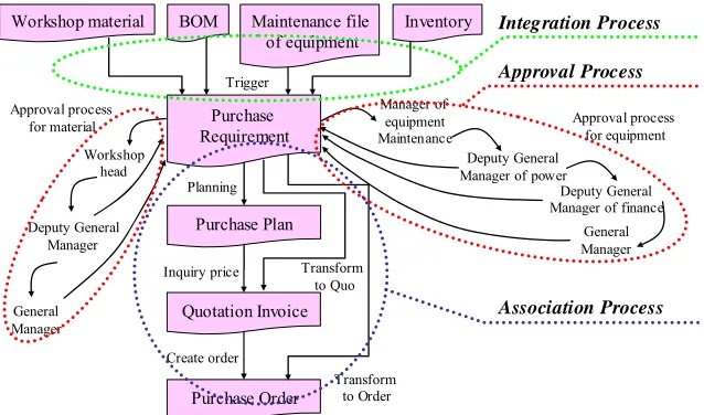
In the real enterprises, business requirements always changes continually, and the changes follows the par-ticular rules. According to our experiences in software development, we find that there are various changes of the business process between the different enterprises, which are in the same industry. In this section, we illus-trate the variable requirements using the Purchase Order as an example. There are the different processes of mak-ing the Purchase Order, and every process represents a
sequence of creating Purchase Order in Figure 1. The
general routes is “submit Requirement schedule Plan
inquire Price build Order” in Process 1. The
op-tional route shows that Purchase Order is refined directly from the Requirement Bill in Process 2, and the route is used for emergency requirements. With the improvement of information degree in enterprise system, the contents of Purchase Requirement in Process 4 can be imported from the records of the material requirements in the workshops, or obtained from computing the replenish-ment amount for inventory. The different types of Pur-chase Requirements, such as large facilities and produc-tion materials in Process 4, will go through the different approval processes.
Although there are different processes which are used for creating the Purchase Order, the business documents in the processes are limited to a certain scope, and they
are Requirement, Plan, Quotation Invoice and Order for purchase. And then, the corresponding forms in each Process have similar kernels, for example, the every Re-quirement Bill contains the data items as follows: keys, Need Department, Item Code, Need Amount and Date etc. Sometimes, these data items may have the different names, but the same semantics. According to the stan-dardization degree, the assistant information in docu-ments may exist or not, such as the data items used for describing state transformation. Therefore, we find that the documents are similar, and there are little differences between them in the same business transactions.
From the analysis above we can know, the processes of making purchase order are various, and essentially the relationships between the documents are various. It’s obvious that the business documents have relative stabil-ity. The business documents are more stable than the business processes. By analyzing the feature of business process, we find that the processes also follow the rules. The relationships between business objects are divided into three types: approval process, association process
and integration process, and they are shown in Figure 2.
The approval process is one of the basic processes in the lifecycle of business documents. The approval process is a set of activities, including auditing and affirming. The people at the different ranks run the activities corre-sponding to their rights. The association process is com-posed of the activities which deal with the many-to-many relationship between two documents. The integration process is an activity set to create new documents through the computation based on one or more existing documents. The computation rules are always compli-cated, and need to be produced by hands. If these rela-tionships are identified clearly, they are implemented based on the particular patterns. Therefore, the difficulty of assembly is reduced to a certain degree.
The business system is thought as dynamic network,
Create order
Purchase Plan
Quotation Invoice
Purchase Order
Inquiry price Transform to Quo
Purchase Requirement
Planning
Transform to Order Create order
Purchase Plan
Quotation Invoice
Purchase Order
Inquiry price
Purchase Requirement
Planning
Create order
Purchase Plan
Quotation Invoice
Purchase Order
Inquiry price
Purchase Requirement
Transform to Order
Process 1
General Manager
Create order
Purchase Plan
Quotation Invoice
Purchase Order
Inquiry price Transform to Quo
Purchase Requirement
Planning
Workshop material BOM Maintenance file of equipment
Inventory
Approval process for material
Deputy General Manager
Workshop head
General Manager
Approval process for equipment
Manager of equipment Maintenance
Deputy General Manager of power
Deputy General Manager of finance Trigger
Transform to Order
[image:3.595.58.537.542.690.2]Process 2 Process 3 Process 4
Create order
Purchase Plan
Quotation Invoice
Purchase Order
Inquiry price Transform to Quo
Purchase Requirement
Planning
Workshop material BOM Maintenance file
of equipment
Inventory
Approval process for material
General Manager
Deputy General Manager
Workshop head
General Manager Approval process
for equipment Manager of
equipment Maintenance
Deputy General Manager of power
Deputy General Manager of finance Trigger
Transform to Order
Integration Process
Approval Process
[image:4.595.143.462.89.277.2]Association Process
Figure 2. Three types of business processes.
and is composed of stable business documents and the various business processes. If the software has been im-plemented only using the approach based on the process, it is difficult to adapt quickly to the new relationships. Therefore, the approach is combined business objects with business processes together in this paper. The proc-ess-oriented requirement analysis is transformed into the object-oriented software development in the approach. First, requirement analysts understand the business proc-esses in the enterprise, and identify the business docu-ments. Second, the business objects are abstracted from the documents by software designers. The objects are as independent as possible, thus they can be reused for the variable processes. Third, the connections between ob-jects are built in the light of current requirements. Finally, the business objects are realized to business components. The business processes are transformed to the coopera-tion relacoopera-tionships among the components, which are supported by the workflow engine. By doing so, we en-able to assemble the flexible software form the business components and workflow engine.
3. Business Object
Basing on the business object from OMG, the business documents and their relationships are identified to
busi-ness object and these three relationships in Figure 3,
respectively. And then, we separate the business seman-tics of business object from its implementation.
Hence, our business objects differ from the objects of OMG in the following aspects: 1) from the perspective of software design, business object is a basic operation unit of system, is a integration of the data and the operations on them; 2) from the view of external application, busi-ness object is an integrated body, including the informa-
Business object A1
Business object A2
Business object A3
Business object B1
Business object B3 Business object B2
Data/General Operation Association Operation
Association Operation
R1 R5
R6 R2
R3 R4
Extended operation
Association Path
Approval Path Integration
Path
State transformation
Path
End
Start
[image:4.595.310.535.310.494.2]Extended operation
Figure 3. The business objects and their relationships.
tion which are collected and transformed by the users, the state transformations and operations which affect on the information, and the state transformation is such as start, running, end; 3) from the view of object-oriented structure, business object has an identifier number, data sets, operation sets, and its own lifecycle; 4) from the view of representation format, the business object repre-sents that some children tables are attached to a father table; 5) from the software implementation view, busi-ness object is implemented to busibusi-ness component with the software technology.
The definition of business object is as follows:
Definition 1: Business Object (BO) is defined as a
ba-sic operation unit with the integral semantics in the field
of enterprise business. Business object is described as BO
1) BOID is the ID number of BO;
2) DS is the data sets. DS = {CDS, {ADS}}; CDS is the
core data set; ADS is assistant data sets. Every data set is
composed of numerous data elements, which have the
same or similar semantics. DS need satisfy the following
constraints: ① CDS≠; ② d is a data element of the
DS.BO, XCDS, X = {d1, d2, d3, …}. But X, there
doesn’t exist more than one xi, xiX, which uniquely
determines the CDS of BO; ③ ADS = {ADS1,
ADS2,…,ADSi,…,ADSn}, ADSi= {dn | dnisdataelement,
dnDS-CDS} and ADSi∩ADSj= , where i, j = 1, 2,
3…; ④ CDS∩ADS = ; ⑤ If ADS = , there is DS
= CDS;
3) OPS is the operation sets of BO. OPS = {GPS,
EPS}, GPS∩EPS = , GPS. GPS is general
opera-tion set, EPS is extended operation set. An operation set
is composed of many associated operations. GPS = {op1,
op2, …, opi, …, opn}, where i = 1, 2, 3…; OPS need
sat-isfy the follow constraints: ① GPS ; ② op is a
operation element of the OPS. BO, YGPS, Y = {op1,
op2, op3, …}. Y, there exists single one yi Y, that
makes GPS exist uniquely; ③ If EPS = , then OPS =
GPS; ④ GPS acts on the CDS at least, else EPS deals
with CD or ADS.
4) SS includes the states and their transformation. SS =
{(Si, Ti)}, where Si= {sis, …,sij, …, sie}, sij is the middle
state in the Si. Si, there exists a start state called ss and a
end state named as se; Ti= { tij| tij= (sim, sin, p), opkp, p
is a ordered set of opk, pOPS. tij represents that BO is
transformed from the present state sim to the next state
sin}.
BO is classified into different categories according to their business functions in the certain industry, for
exam-ple, the class of Purchase Requirement, the class of
Equipment Maintenance, the class of Warehouse Entry
etc. Every category of BO is an abstract set of business documents, which have the similar features. One of the classes is further divided into children classes according
to the concrete semantics. For instance, the class of
Pur-chase Requirement has children classes as follows: the
requirement for production material, the requirement for equipment, the requirement for office etc.
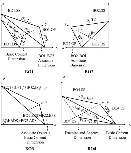
BO describes all of the semantics at the range of busi-ness document. The semantics is partitioned into some semantic dimensions. Every semantic dimension contains three planes: data, operations and states. Every plane is
made up of two axes. The data plane is P(x, z),
opera-tions plane is P(x, y), and states plane is P(y, z). Thus,
semantic dimension is defined as BSD (id, BOID.ds,
BOID.op, BOID.ss), where BOID.ds DS, BOID.op
OPS, BOID.ss SS. When the operation is triggered in
one dimension, the values of data and states will be
changed in the same semantic dimension. Figure 4 gives
an example to illuminate what is semantic dimension in
BO. The main semantic dimension of Purchase
Re-quirement is a cross section, which is composed of CDS,
GPS and Running state, where CDS = {Bill identifier,
Material item, Requirement amount, Requirement
date, …}, GPS = {Insert, Modify, Delete, Release,
Per-form, …} and Running state is set (S00,T00) = {{
NewCre-ated state, Released state, Running state, Finished state},
{( NewCreated state, Released state, Release), (Released
state, Running state, Perform)…}}.
We proceed to define the three relationships based on
the semantics partition, which are shown in Figure 2.
The definition of approval relationship is as follows:
Definition 2: Approval Relationship is defined as a
set of AP, is a series of the approval actions. The
ap-proval action is represented as a node. The AP = (StepID,
Precondition, Roles, Operation, Next StepID), where
StepID is the node identifier. This node is visited when
the precondition has been prepared. Roles = {role | role
hasthe rightsto perform the approval operation}.
Op-eration = { a | a represents op (a = acceptora =
re-ject)}, NextStepID = { b | b represents StepID, where b = xiffOperation = accept, orb = yiffOperation = reject, x,
y {StepID}}.
After the auditing people finish the operations, the val-ues of auditing dimension will be updated, and than the BO will be transformed to the next steps, in where the
transformation path are predefined in AP. There exist
many different approval paths for a BO, because the en-terprises apply the extensive or intensive management pattern.
The auditing relationship is an ordered route in the au-diting dimension. For instance, the approval dimension
involves the following elements: ADSi = {approval
ac-tion ID, people name for approval, approval date,
ad-vice}, EPSi= {Query, Accept, Reject} in the approval
actionm, where m=1,2,3,…,n. (Sij,Tij) = {{WaitingState,
AcceptedState, RejectedState}, {(WaitingState for
Ap-proval, Approving, Acceptintheaction1),…, (Approving,
AcceptedState, Acceptintheactionn)}}.
The approval relationship has effects on the inner of one BO. On the contrary, the association and integration relationships are built on the corresponding semantic dimensions among Business Objects (BOs). When two BOs are connected with the relationships of association or integration, the any operation of BO may change the state of the other BO.
For the association relationship between two BOs, a
middle BO named as Association Object bridges many-
to-many relationship of data. In Figure 4, BO3 is an
BO1.SS
BO1.DS
BO1.OP
Basic Content
Dimension BO1-BO2Associate Dimension ADS
i (S
ij,T ij)
EP S
i
CDS
(S
00,T 00)
GPS
BO1
x y z
BO2.OP
BO2.SS
BO2.DS
BO2-BO1 Associate Dimension
ADS
j
(Sjj,Tjj)
EPS j
BO2
x y
z
BO1.ADSi+BO2.ADSj
BO1.EPSi+BO2.EPSj
BO1.(Sij+Tij)+BO2.(Sjj+Tij)
Associate Object’s Basic Content
Dimension
BO3
z
x y
BO4.SS
BO4.DS
BO4.OP
CDS=F(BO 1.CDs) (S00,T
00)
G PS
BO4 EPS={Y,N}
Examine and Approve Dimension
Basic Content Dimension z
[image:6.595.59.286.82.348.2]x y
Figure 4. Business semantic dimensions.
Definition 3: Association Relationship.
BO1, BO2BO, if BO1 is associated to BO2, the
fol-lowing condition must be prepared:
1) There is BO2-oriented semantic dimension named
as BSD1 (BO1.ASS, BO1.ADSi, BO1.EPSi, BO1. (Si,Ti)). At
this moment, the every element of this tuple has special
semantics. The data element of BO1.ADSiis associated to
the data element of BO2. The EPSi is an operation set,
which connects the data mapping from BO1 to BO2.
BO1.(Si,Ti) represents the association states in this
di-mension of BO1, whose values will be changed because
of this mapping.
2) BO2 also has the BO1-oriented semantic dimension,
named as BSD2 (BO2.ASS, BO2.ADSj, BO2.EPSj,
BO2.(Sj,Tj)), the others are similar to (1).
3) There exists one association object, represented as
BO3 (BO3, BO3.DS, BO3.OPS, BO3.SS), Where BO3.CDS
= BO1.ADSi BO2.ADSj; BO3.GPS = BO1.EPSi
BO2.EPSj; BO3.SS = {(S0, T0), BO1.(Si, Ti), BO2.(Sj, Tj)},
it is composed of the RunningStates (S0,T0) in BO3 and
association states.
The core data set of association object is composed of data in these BOs which associate with each other. There are three types of associations according to the functions of data items, such as the association between data items, the association between keys, the association between
keys and attributions. In association object, the ADS
contains data elements as follows: Creator, Creating
date, the Last Modifier, the Last Modifying Date etc. In
the complex system, the association is bidirectional and
transmissible. For example, the Process 1 in Figure 1
shows that there is a direct association between the
Pur-chase Requirement and Purchase Plan. The numerous
records of materiel requirement are combined into one
purchase task of Purchase Plan. And then the Purchase
Order is transformed from the Purchase Plan. Thus, the
indirect association between the Requirement and Order
is connected. The object of Purchase Requirement can
build many direct or indirect association paths with the other objects in its lifecycle. The subsequent records in the business process can be traced to the sources along the paths. By doing so, the intensive management keeps at the fine granularity in the enterprise.
Definition 4: Integration Relationship.
BO1, BO2BO, there exists BO1(BO1, BO1.DS,
BO1.OPS, BO1.SS) and BO2(BO2, BO2.DS, BO2.OPS,
BO2.SS). There is not less than one d = F(BO1.d1,…,
BO1.dn) in BO2.CDS, where F is formula used for
com-puting value of BO2. Thus, there exists the integration
from BO1 to BO2.
In real enterprise, the part values of business object are obtained from many business objects through the com-plex computation. Therefore, the definition 4 can be
ex-tended. If there are integration relationships in the BO1,
BO2, …, BOn and BOj, BOj (BOj, BOj.DS, BOj.OPS,
BOj.SS) must satisfy that there exists no less than one
data item d = F(BO1.d1, …, BOi.dk, …, BOn.dn), where F
is formula used for the computation from BOi to BOj,
1inj. Generally, the formula F is various in different
enterprises. Therefore, the implementation of F is second development by the programmers. The operation patterns
of integration are classified into Push Integration and
Pull Integration. The pattern called Push Integration
need satisfy the following constraints: 1) the lifecycle of
BO1 is earlier than BO2; 2) the operator in BO1 is used for
triggering the integration; 3) the BO1 starts the
integra-tion, and BO2 receives the messages. On the contrary, the
Pull Integration is that the trigger operation belongs to
BO2, and BO2 is defined as active object.
4. BOSD
4.1. Basic Thinking
In this section, we propose the software development approach that combines business object and business
process together. The basic thinking is shown in Figure
5.
is a set of documents. The ACTION’ defines the set of
activity, which is executed by the ORG and acts on the
ORDER. Finally, the information objects are abstracted
from business documents which are used in the process models. Thus, the function-oriented requirements are collected clearly.
Management pattern
Business process
Bill of Document /Information Object
Require ment Analysis Phase
Business
object Business Action Business process Analyze and Abstract
Design
Business Component
The executable workflow model (workflow engine)
Implement Transform
Software Design Phase
Software Imple mentation Phase
Management Model /Decision Model
Implement
Aiming to enhance the independence of business ob-ject, the functions acting on the information objects are combined with the information objects to business object in the phase of software design. The business objects are connected to business processes by the business actions. For designing the flexible software using this approach, the approval, association and integration relationships are
implemented by the particular approach in Figure 6. The
[image:7.595.58.288.90.233.2]software development is followed these steps: 1) the business component corresponding to the special BO is developed independently; 2) the inner relationships, such as the approval process and state transformation, are firstly considered to implementation; 3) when the whole business object is designed clearly, we connect them us-ing the association relationship. And we define the state transformation which is affected by the associations un-der the control of association mechanism; 4) at last, the complicated integration relationship is developed by the extended mechanism, including automatic data import, computation and carrying forward etc.
Figure 5. The process of BOSD.
defined as DecisionModel = (H/P, FUNC, ORDER,
De-cisionCenter), where, H/P is row and FUNC is columns;
H/P represents the different decision granularity, and is
used for defining the time span (such as year or month) or different decision layers (such as stratagem layer, tac-tics layer and operations layer); A business target is gen-erally realized by the collaborative activities, each of which is executed respectively by the different
depart-ments. FUNC is a set of functions. FUNC is described as
a set of relationships, which are used for realizing a
common target. The DecisionCenter is a cross cell of the
row and column, and is defined as {order | order =
f(h/p,func), h/pH/P, funcFUNC}. The order
repre-sents an instruction, which is always saved in the busi-ness document. Second, we can produce the busibusi-ness process models through tracing the physical transforma-tion from the materials to the products. The business process in the requirement analysis phase is defined as
follows: Process Model = (IP, ORG, DOC, ORDER,
ACTION’), where the IP is the information entity,
repre-sents an instruction or document in process model. The
IP = {ip | ip = orderorip = docandorderORDER, doc
DOC}. The ORG represents the department set. DOC
In the development phase, business components are transformed from BOs, the relationships between them are implemented to executable workflow model. Thus,
the workflow model is defined as (BO.DS, BO.AT, CON,
ATRelation, RoleSet), where the BO.DS is the set of data;
BO.AT represents the activity set, is mapping to the
BO.OPS. CON = {conditionx→y| condition is the
trans-formationconditionfromtheactivityxtoy}; The
ATRe-lation is the transformation rules, is defined as
ATRela-tion = { f | y=f(x) iff conditionx→y=true, xBOi.AT,
yBOj.AT, i,j=1,…,n}; RoleSet is the roles which take
part in the BO.AT.
Purchase Plan
Quotation Invoice
Purchase Order Purchase Requirement
General Manager
Purchase Plan
Quotation Invoice
Purchase Order Purchase Requirement
Deputy General Manager
Workshop head
General Manager Manager of
equipment Maintenance
Deputy General Manager of power
Deputy General Manager of finance
Create order
Purchase Plan
Quotation Invoice
Purchase Order
Inquiry price Transform to Quo
Purchase Requirement
Planning
Transform to Order
Step (4) Purchase Plan
Quotation Invoice
Purchase Order Purchase Requirement
Workshop material BOM Maintenance file
of equipment
Inventory
Trigger
Step (3) Step (2)
[image:7.595.54.539.560.709.2]Step (1)
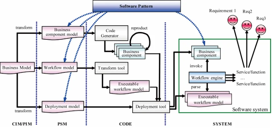
4.2. Development Framework
The methodology introduced in Section 4.1 is very enor-mous and need to be supported by software technology. Hence, we choose the platform named as ICEMDA (In-teroperable Configurable Executable Model Driven Ar-chitecture) [22,23] to implement this thinking. The
plat-form has been developed mostly and is shown in Figure
7. There are five phases using this platform to develop
the software for enterprise as follows: building the CIM for business requirement, building the PIM for the soft-ware design, and building the PSM for implementation on particular platform, generating the components from PSM, and assembling the components to a system.
The models in the requirement analysis phase are structured as decision model, business process model, information model and organization model on the sup-port of using graphical modeling tools [24] on the CIM layer. The models on the CIM level are semi automati-cally transformed to the models on the PIM level, which involves business object models, BO-based workflow model, role-dependent model and data model. The three relationships above mentioned are described detailedly in the BO-based workflow model on the PIM layer. And then the PIM is refined to the PSM on J2EE platform, such as business component model ( the model for com-ponent implementation ) based on a specific software pattern, the executable workflow model, and the de-ployment model which defines the assembly of business component and workflow model. The business compo-nent is produced from the Platform-specific compocompo-nent model by code generator [25], and then can be secondly developed for meeting the special requirements. In the system for enterprise, the workflow engine parses the
workflow models, and then choreographs the compo-nents to supply the different services to the clients.
4.3. BO and Relationships Expression
We illustrate the expression of BO and the relationships using a purchase management system. The business
ob-jects of purchase system are purchase requirement,
quo-tation, purchaseplan, purchaseorder, arrivalnotice and
advice of settlement etc.
According to the definition 1, the contents of BO are described by the graphical platform-independent models in Figure 8. There are four types of platform-independent
models which correspond to the data, state and operation set in Definition 1, and they are the data diagram, state diagram and class diagram. The use case diagram is mapping to the role-dependent model, which represents the roles act on the business objects in the workflow model.
The relationships between BOs in the Section 3 are described by a special relationship object called BOR (Business Object Relationship). The BOR can be imple-mented into three instances: association object, auditing object and integration object. And the BOR is also made up of the rules from the views of the data, operations and
states. We can define the BOR = {fR(BOi, BOj) | fR = (r1
… rk), r1, …, rk R}, R = { r | r = f(xsm, xsn), xsmBOi.XS, xsnBOj.XS, 1 m |BOi.XS|, 1 n
|BOj.XS|, where x = d |op |s, X = D|OP|S }. The Process
[image:8.595.81.516.501.707.2]4 in Figure 1 is modeling to the class diagram, which is shown in Figure 9. The bold lines represent the source process, and every BO has its own auditing object, just like the Auditing 2 for materiel. The graphical model is used for understanding easily, and further the model is
CDS primary Key
<BO> CDS / Entity 1 <BO> ADS2 / Entity 3
<CDS primary key> (FK) <ADS2 PK>
<BO> ADS1 / Entity 2 <CDS primary key> (FK) <ADS2 PK>
<BO> ADS3/ Entity 4 <CDS primary key> (FK) <ADS3 PK> includes
includes includes
BO:IDEF1x Diagram
BO: State Diagram
State1 State2
State3 State4
BO: use case Diagram
<<include>>
<<include>>
<<extend>>
<<extend>> Use case name
Role name
User 1 User 2
Role-specific object
Role-specific
data set Data set
Operation set Role-specific
operation set
BO: Class Diagram
Class 1 Class 2
[image:9.595.58.288.87.399.2]Class 3 Class 4
Figure 8. The BO platform-independent model.
<<BO>> No3:Purchase plan
<<BO>> No4: Quotation Invoice
<<BO>> No5: Purchase Order
<<BOR>> Integration 1-2 <<BOR>>
Association 1-2
<<BOR>> Association 2-3
<<BOR>> Association 3-4
<<BOR>> Association 4-5 <<BO>>
No1:Workshop material
<<BOR>> Auditing 2 for materiel
<<BO>> No2:Purchase requirement
Figure 9. The class diagram of BOs.
saves as the file in XML (eXtensible Markup Language).
Thus, the BOR is expressed as the fragment of XML.
When the PurchaseRequirement is arranged into
Pur-chase Plan, the association relationship between them
has been built. It’s defined as the following XML list: <associationSet>
<ass AssBOId="No2-No3">
<AssedObject BOId="No2"
name=”Requirement”
assString="Need_code,Material_code, Material_name,needNum">
</AssedObject>
<AObject BOId=" No3"
name=”Purchase Plan”
assString="Plan_code,Material_ID,PlanNum"> </AObject>
<assCondition>
Material_code = Material_ID </assCondition>
</ass>
</associationSet>
The second example is that Purchase Order is
ap-proved by the appropriate roles, each of which has the permission right according to the material type or money
amounts. Thus the approval relationship of Order can be
described as:
<ApprovalPath BOId="No5"> <step StepId="start"
personString="dept manager"
condition="money<=50000 and money>0 or ma-trial belongto 'steel'"
nextStep="accept?first:goback"></step> <step StepId="first"
personString="assistant manager" condition="money<=100000 and money>0"
nextStep="accept?second:goback"> </step>
<step StepId="second" ...></step>
<step StepId="end" personString="manager" condition="money>100000"
nextStep="accept?gonext:goback"></step> </ApprovalPath>
The third example: when the material in workshop
lacks abruptly, the record of Requirement No2 is
achieved through importing the data of Workshop
Mate-rial Requirement. For supporting this process, that
inte-gration relationship between these objects need be prede-fined. When the delivery date is satisfied, the integration
formula F = {Order.needNum = ∑ Requirement.
Mate-rial-Num}. The operator used for triggering the Pull
In-tegration is defined as follows:
<extendOpSet>
<extendOp opID="ExtendedOP"
opName="import from Workshop Material Re-quirement ">
<whereRun BOId=”Order”></whereRun> <! —Pull Integration-->
<function> Order.needNum = sum (Requirement.
[image:9.595.61.287.423.598.2]<condition> Order. needNum, Order. time </condition>
…
</extendOp> </extendOpSet>
5. Related Works
Several researchers have done work on developing en-terprise software based on business object. Typical ap-plications are requirement engineering, software design and implementation. Generally, the business object is used for implementation of business logic, which is composed with appropriate presentation object or web application to become an integrative application for the terminal clients. However, with the improvement of the enterprise software, business object is considered impor-tant object type. The business object type, technical ob-ject type and application obob-ject type are three types of objects based on the principle of separation of concern [26]. And then the business objects are specialized to common business objects, industry specific business ob-jects, company specific business objects and user specific business objects according to the individual requirements of the different roles [27]. Therefore, the business objects are defined as components of the enterprise software that directly represent the business model. The largest granu-larity of business objects are cooperative business object (CBO) [28]. The CBO is considered the end product of the development process and cooperates with other ob-jects to perform some desired task.
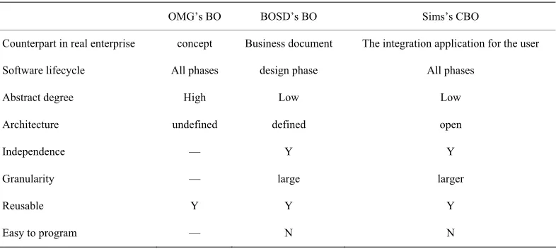
The different business objects have different applica-tion scenarios, therefore the characteristics of business
object are diversity. In Table 1 we give the comparisons
between our business object and the common BO from OMG and the CBO from O Sims [28]. On one hand, the BO in this paper is lower level than the OMG’s BO. On
the other hand, the BO in this paper, which is the compo-sition of many fine-grained objects, is one kind of the smaller scale CBO. These fine-grained objects always cooperate partially to meet the requirement in the range of business documents. The software development based on the different BOs is also comparatively diversity. We compared our BOSD to the business process-based methodology which is proposed by Somjit and Dentcho
[14] under the background of Figure 1. The number of
BOs in Figure 1 is twenty, including eight BOs, eight
auditing objects, four association objects and four inte-gration BORs; the number of BO is eight in the method proposed by Somjit. Although they are coarse-grained objects, the reconfiguration cost of BOSD is mostly half of the other method. We only modify the information of the BORs to meet the processes changes.
According to the comparison above mention, our busi-ness objects are closest to the component-based imple-mentation for enterprise software. A benefit of our ap-proach is that it defines clearly the relationships between the business objects. The model for software design which is composed of business objects and the relation-ships is easily transformed on the MDA platform.
6. Conclusions
[image:10.595.103.496.546.722.2]In this paper, aiming at the problem that current flexible software development methods lack of the systemic methodology and technology support, we present an ap-proach based on coarse-grained business object. By ana-lyzing the changeability of business processes and stabil-ity of business objects, we abstract an independent busi-ness object as the unit of development and reconfigura-tion. The three relationships among business objects are defined to describe the variable business processes. Thus, the business objects are assembled to system through their relationships. The implementation of this approach
Table 1. Comparisons between the BOs in literatures.
OMG’s BO BOSD’s BO Sims’s CBO
Counterpart in real enterprise concept Business document The integration application for the user
Software lifecycle All phases design phase All phases
Abstract degree High Low Low
Architecture undefined defined open
Independence — Y Y
Granularity — large larger
Reusable Y Y Y
Easy to program — N N
is supported by the ICEMDA platform.
In conclusion, there are several innovations in the method presented in this paper, as follows: 1) analyze the variable features of the enterprise system, and find out the flexible software can be composed of the changeable business processes and stabile business objects; 2) pre-sent an explicit definition of coarse-grained business ob-ject; 3) make clear the typical relationships between the business objects; 4) present an method for the flexible software development based on the stable business object, which is implemented by the MDA.
Future works includes: further research on the other relationships between business objects, automatic identi-fication from the business processes, complete the auto-matic transformation from the PIM to PSM on the plat-form ICEMDA, etc.
7. Acknowledgements
This work is supported by State 863 High-Tech Program (No. 2009AA04Z153) and State Natural Science Foun-dation (No. 60773064) of China. The author would like to thank reviewer’s helpful suggestions for revising this paper.
REFERENCES
[1] J. Kramer and J. Magee, “The Evolving Philosophers Problem: Dynamic Change Management,” IEEE Trans-actions on Software Engineering, Vol. 16, No. 11, 1990, pp. 1293-1306.
[2] W. J. Kettinger and V. Grover, “Special Section: Toward a Theory of Business Process Change Management,” Journal of Management Information Systems, Vol. 12, No. 1, 1995, pp. 9-30.
[3] D. Kim, M. Kim and H. Kim, “Dynamic Business Proc-ess Management Based on ProcProc-ess Change Patterns,” Proceedings of the 2007 International Conference on Convergence Information Technology, Gyeongju, 2007, pp. 1154- 1161.
[4] P. Soffer, B. Golany and D. Dori, “Aligning an ERP Sys-tem with Enterprise Requirements: An Object-Process Based Approach,” Computers in Industry, Vol. 56, No. 6, 2005, pp. 639-662.
[5] G. Pour, “Moving toward Component-Based Software Development Approach,” Proceedings of the 27th Tech-nology of Object-Oriented Languages (TOOLS 27), Bei-jing, China, 1998, pp. 296-300.
[6] J. Kotlarsky, I. Oshri, K. Kumar and J. van Hillegersberg, “Towards Agility in Design in Global Component-Based Development,” Communications of the ACM, Vol. 51, No. 9, 2008, pp. 123-127.
[7] Architecture Board ORMSC, “Model Driven Architecture (MDA),” OMG document number ormsc/2001-07-01. 2001. http://www.omg.org/cgibin/doc?ormsc/2001-07-01. pdf.
[8] E. Breton and J. Bézivin, “Model Driven Process Engi-neering,” Proceedings of the 25th Annual International Computer Software and Applications Conference ( COMP-SAC 25th), Chicago, Illiois, 2001, pp. 225-230.
[9] J. Koehler, R. Hauser, S. Kapoor, F. Y. Wu and S. Ku-maran, “A Model-Driven Transformation Method,” Pro-ceedings of the 7th Enterprise Distributed Object
Com-puting Conference, Brisbane, Queensland Australia,
16-19 September 2003, pp. 186- 197.
[10] M. P. Gervais, “Towards an MDA-Oriented Methodol-ogy,” Proceedings of the 26th Annual International Computer Software and Applications Conference ( COMP-SAC 2002), England, 26-29 August 2003, pp. 265-270. [11] M. Keith, H. Demirkan and M. Goul, “Service-Oriented
Software Development,” Proceedings of the 2009 Ameri-cas Conference on Information Systems (AMCIS 2009), 2009, America, p. 100.
[12] P. Wohed, W. Vander Aalst, M. Dumas and A. Ter, “On the Suitability of BPMN for Business Process Modeling,” Business Process Management, Vol. 4102, 2006, pp. 161- 176.
[13] D. Hollingsworth, “The Workflow Reference Model,” Technical Report, Workflow Management Coalition, TC00-1003, December 1994.
[14] A. Somjit and B. Dentcho, “Development of Industrial Information Systems on the Web Using Business Com-ponents,” Computers in Industry, Vol. 50, No. 2, 2003, pp. 231-250.
[15] S. Arbaoui, J. C. Derniame, F. Oquendo and H. Verjus, “A Comparative Review of Process-Centered Software Engineering Environments,” Annals of Software Engi-neering, Vol. 14, No. 1-4, 2002, pp. 311-340.
[16] R. Sangwan, C. Neill, M. Bass and Z. E. I. Houda, “Inte-grating a Software Architecture-Centric Method into Ob-ject-Oriented Analysis and Design,” Journal of Systems and Software, Vol. 81, No. 5, 2008, pp. 727-746.
[17] I. Reinhartz-Berger, D. Dori and S. Katz, “OPM/ Web-Object-Process Methodology for Developing Web Applications,” Annals of Software Engineering, Vol. 13, No. 1-4, 2002, pp. 141-161.
[18] H. Liu and D. P. Gluch, “Conceptual Modeling with the Object-Process Methodology in Software Architecture,” Journal of Computing Sciences in Colleges, Vol. 19, No. 3, 2004, pp. 10-21.
[19] W. Kozaczynski, “Architecture Framework for Business Component,” Proceedings of the 5th International Con-ference on Software Reuse, Canada, 2-5 June 1998, pp. 300-307.
[20] A. Karakaxas, B. Karakostas and V. Zografos, “A Busi-ness Object Oriented Layered Enterprise Architecture,” Proceedings of the 11th International Workshop on
Da-tabase and Expert Systems Applications, Greenwich,
London, U.K., 4-8 September 2000, pp. 807-810
[22] L. Nie, X. Xu, C. David, Z. Gregory and D. Zhan, “GRAI-ICE Model Driven Interoperability Architecture for Developing Interoperable ESA,” The International Conference on Interoperability for Enterprise Software and Applications, United Kingdom, 12-15 April 2010, pp. 111-121.
[23] D. Zhan, J. Feng, L. Nie and X. Xu, “ICEMDA: An In-teroperable Configurable Executable Model Driven Ar-chitecture,” Chinese Journal of Electronics, Vol. 36, No. 12A, 2008, pp. 120-127.
[24] J. Li, D. Zhan, L. Nie and X. Xu, “Design and Imple-mentation of a MOF Based Enterprise Modeling Tool,” I-ESA, China, 2009.
[25] J. Feng, D. Zhan, L. Nie and X. Xu, “Pattern Based Code
Generation Method for the Business Component,” Chi-nese Journal of Electronics, Vol. 36, No. 12A, 2008, pp. 19-24.
[26] R. Shelton, “Business Objects Response from Open En-gineering Inc. to OMG BODTF RFI-1,” http://www. OMG.com/OMG Document bom/97-10-07
[27] C. Casanave, “Business-Object Architectures and Stan-dards,” Proceedings of the 10th Annual Conference on Object-Oriented Programming Systems, Languages, and Applications (OOPSLA’95), USA, 1995.