Genetic Algorithm Based Performance Analysis of Self
Excited Induction Generator
Hassan Ibrahim, Mostafa Metwaly
Department of Electrical and Computer Control Engineering, Arab Academy for Science, Technology and Maritime Transport, Cairo, Egypt
E-mail:{hibrahim_eg, mostafiii}@yahoo.com
Received June 8, 2011; revised July 6, 2011; accepted July 20, 2011
Abstract
This paper investigates the effects of various parameters on the terminal voltage and frequency of self ex-cited induction generator using genetic algorithm. The parameters considered are speed, capacitance, leakage reactance, stator and rotor resistances. Simulated results obtained using genetic algorithm facilitates in ex-ploring the performance of self-excited induction generator. The paper henceforth establishes the application of user friendly genetic algorithm for studying the behaviour of self-excited induction.
Keywords:Self-Excited Induction Generator, Genetic Algorithm Toolbox, Frequency, Terminal Voltage
1. Introduction
The self-excited induction generators (SEIG) have been found suitable for energy conversion for remote locations. Such generators may be commonly used in the remote areas. These machines can be used to meet the local de- mand of remote areas in the absence of a grid. SEIG has many advantages such as simple construction, absence of DC power supply for excitation, reduced maintenance cost, good over speed capability self short-circuit protec- tion capability and no synchronizing problem [1]. In the last two decades self excited induction generator has attached considerable attention due to its application as a standalone generator using conventional and non con- ventional energy sources.
Self excitation in an induction machine occurs when the rotor is driven by a prime mover and a suitable ca- pacitance is connected across the stator terminals the machine operating in this mode is called a self excited induction generator (SEIG) which has been increasingly utilized in stand-alone generation systems that employ wind or hydro power. The frequency and value of the voltage generated by these generators are highly de- pendent on speed, excitation capacitance and load [2,3]. The performance characteristics of a self-excited induc- tion generator can be obtained after the determination of two unknown parameters, such as the magnetizing reac- tance and frequency. Usually, Newton-Raphson method and Nodal-Admittance.
Method are used to determine the generator’s un-
known parameters which are the conventional methods used since three decades. If either of these two methods is used, lengthy mathematical derivations should be car- ried out to formulate the required equations in a suitable simplified form. The real and imaginary term separations are carried out by hand [4]. Genetic algorithm (GA) is a stochastic optimization technique. It is simple, powerful, reliable, derivative-free stochastic global optimization tech-nique (search algorithm) inspired by the laws of natural selection and genetic. This algorithm is derivative-free in the sense that it does not need functional derivative in-formation to search for a set solution that minimizes (or maximizes) a given objective function [5]. This paper deals with the implementation of intelligent approach, based on genetic algorithm, for the performance analysis of self-excited induction generator. Unlike conventional methods of analysis, lengthy algebraic derivations or accurate initial estimates are not required. In addition, the same objective function is to be minimized irrespec-tive of the unknown parameters. The other important feature of the present approach is the possibility of de-termining more than two unknown parameters simulta-neously. Therefore, it can be used to obtain the perform-ance characteristics of three-phase self-excited induction generator
2. Analysis of SEIG
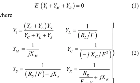
may be analyzed by using genetic algorithm, the equiva- lent circuit representation [6] is shown in Figure 1.
RS, RR, RL are the stator, rotor and load resistances re-
spectively. XS, XR, XM, XC are the stator, rotor, and
mag-netizing and excitation reactance respectively. YS,
YR, YM, YL, YC are the stator, rotor, magnetizing, load and
excitation admittances respectively. F is the P.U
fre-quency. v is the P.U speed which is the ratio between
rotor speed and synchronous speed. IS, IR, IL, are the sta-
tor, rotor and load currents respectively. Vg, VT, E1 are the
P.U air gap, terminal voltage and air gap voltage at rated frequency respectively.
The total current at node “a” in Figure 1 can be writ-ten as in the following Equation (1):
1 1 M R 0
E Y Y Y (1)
where
1 2 1 1 1 1 1C L S
L
C L S L
M C M C S R R S S R
Y Y Y
Y Y
Y Y Y R F
Y Y
jX j X F
Y Y
R
R F jX
jX F v (2)
Under self-excitation E1≠ 0, therefore the sum of total
admittance connected across the air gap must be zero [7,8], i.e.
1 M R 0
Y Y Y (3)
1
Real Y YM YR 0 (4)
1
Imag Y YM YR 0 (5)
For given value of the shaft speed, generator parame- ters, excitation capacitance and load impedance, solution of Equation (4) gives the frequency F in P.U.
Then, corresponding value of magnetizing reactance
XM can be calculated from Equation (5) using the value
of Fobtained from Equation (4).
After determining the values of F and XM, the air gap
voltage E1 can be determined from the experimentally
obtained magnetization curve, which relates Vg/F and XM.
[image:2.595.308.541.77.208.2] [image:2.595.61.289.249.385.2]By applying mesh current method, to the model given in
Figure 1, the stator current (IS) and the current of the
load (IL) can be determined from the following equation
(6),
2
g S
S C L
S
L C
C S
L t L L
L C
E F I
R jX R
jX
F F R jFX
jX I
I V I R
R F jX
(6)
Figure 1. Per phase equivalent circuit of SEIG.
3. Genetic Algorithm
Different from conventional optimization methods, the GA was developed based on the Darwinian evolution theory of “survival of the fittest”. It has produced good results in many practical problems and has become a powerful tool for solving nonlinear equations. The GA manipulates strings of binary digits and measures each string’s strength with a fitness value. The main idea is that stronger strings advance and mate with other strong strings to produce offspring. Finally, one string emerges as the best. Another important advantage is that it offers parallel search, which can overcome local optima and then finally find the globally optimal solution.
The mechanics of the GAs are elementary, involving nothing more than copying strings, random number gen- eration, and swapping partial strings. A common GA is mainly composed of three operators: reproduction, cross-over, and mutation. GA for this particular problem has the following components [9]:
1) Genetic representation for potential solutions to the problem.
2) A way to create an initial population of potential solutions.
3) Evaluation function that plays the role of the envi- ronmental rating solutions in terms of their “fitness”. This is because the population undergoes a simulated evolution at each generation. This role of an environment helps relatively “good” solutions to reproduce, while rela-tively “bad” solutions die.
4) Genetic operators then alter the composition of children. The multidirectional search is performed by maintaining a population of potential solutions and en- courages information exchange between these directions. 5) Values for various control parameters that the GA uses (e.g., population size, probabilities of applying GA).
Genetic Algorithm Based Modeling of SEIG
reactance (XM), Equation (3) can be considered to be the
objective (Fitness) function for the GA.
1 0
Subject to 0.9 0.99 100 200
M R
m
Y Y Y
F
X
(7)
The objective function is minimized subjected to con- strain shown in Equation (7). The first constrain involves that the induction generator must operate in the satura- tion region which means the magnetizing reactance is always less than the unsaturated value and the second constraint involves that the obtained frequency must be less than the prime mover’s speed.
The 1st step comes with GA optimization started with a population of randomly generated individuals repre-senting a set of solutions for the problem. Each individ-ual is composed of the problem’s variables the popula-tion size is chosen to be 160. The 2nd step comes with computing the fitness function for the entire available elements for such parameter. The 3rd step select two parents from a population according to their fitness (the better fitness, the bigger chance to get selected) which the roulette wheel selection is applied followed by uni-form cross over with probability of 0.8. The 4th step is the death process eliminate all population, which have bad fitness according to a crossover probability of 0.8 the 5th step is the crossover process to generate offspring to keep up the same number of population and to have im-proved parameters values. The crossover process uses the parents with best fitness, a binary coding is used to express weight’s magnitudes, and single-point crossover method is used in our case. The 6th step is the mutation process with mutation probability of 0.05, finally, the new population is formed and procedures repeated until reaching the accuracy € < 0.001 [11-13].
After determining the values of F and XM, the air gap
voltage Vg can be determined from the experimentally
obtained magnetization curve, which relates Vg/F and XM.
[image:3.595.330.515.187.566.2]By applying mesh current method, to the model given in
Figure 1, the stator current (IS) and the current of the
load (IL) can be determined from the Equation (6).
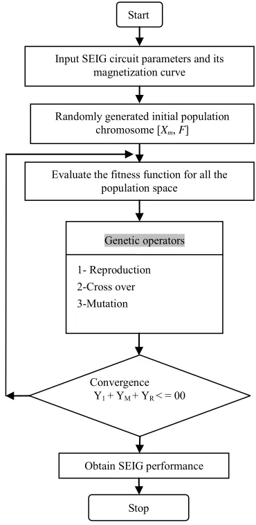
The flowchart describing the GA optimization tech- nique implemented in this paper is shown in Figure 2.
4. System Results and Simulation
The simulated results are obtained by using GA toolbox on machine with specifications given in Appendix, Ta- ble 1 gives the details of each data set taken on test ma- chine the range of speed and value of terminal capaci- tance have been chosen to enable the machine to supply power to the connected load at rated voltage. The resis- tive load is not sensitive to the changes in frequency.
Therefore, the two values of load resistance were chosen arbitrarily.
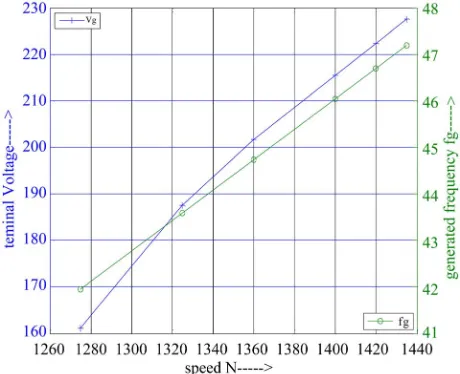
Figures 3 and 4 show the variation of terminal voltage and generated frequency with different speed values with capacitance (36 µF) and different value of resistive load (160 Ω, 220 Ω) , it is shown that the value of termi-nal voltage and generated frequency increase with in-creasing the speed.
Start
Input SEIG circuit parameters and its magnetization curve
Randomly generated initial population chromosome [Xm, F]
Evaluate the fitness function for all the population space
Genetic operators
1- Reproduction 2-Cross over 3-Mutation
Convergence Y1 + YM + YR < = 00
Obtain SEIG performance
Stop
[image:3.595.311.537.620.713.2]Figure 2. flow chart of GA for steady state analysis of SEIG.
Table 1. The input data (N, C, R).
Speed RPM Set
No. From To C (µF) R (Ω)
No. of Samples
Figure 5 shows the best fitness value and average fit- ness versus the iterations at C = 36 µF, R = 160 Ω and N
= 1435 r.p.m, the best fitness reach to zero at iteration number 51.
Figure 3. Voltage and frequency versus speed at C = 36 µF and R = 160 Ω.
Figure 4. Voltage and frequency versus speed at C = 36 µF and R = 220 Ω.
Figure 5. Best fitness value and average fitness value versus iteration at C = 36 µF and R = 160 Ω.
Figure 6 shows the values of the best individuals at F
= 0.9451 P.U, XM = 102.8225 Ω (that having the best
fitness values) in each generation at C = 36 µF, R = 160
Ω and N = 1435 r.p.m.
Figure 7 shows the minimum, maximum and mean fitness function values versus the iterations. The vertical line shows the range from the smallest to the largest fit- ness value, at C = 36 µF, R = 160 Ω and N = 1435 r.p.m.
Figure 8 shows the average distance between the in- dividuals versus the iterations, which is a good measure of the diversity of a population at C = 51 µF, R = 160 Ω
and N = 1435 r.p.m.
Figure 9 shows the variation of terminal voltage and generated frequency with different speed values with capacitance (51 µF) and different value of resistive load (160 Ω) , as shown that the value of terminal voltage and generated frequency increase with increasing the speed.
Figure 6. The best individuals values at last iteration (num-ber 51) at C = 36 µF and R = 160 Ω.
Figure 8. The average distance of individuals versus itera- tions at C = 36 µF and R = 160 Ω.
Figure 9. Voltage and frequency versus speed at C = 51 µF and R = 160 Ω.
Genetic algorithms have been used for difficult prob- lems for machine learning and also for evolving simple programs. The result obtain from GA is more accurate from another conventional method because the GA work to find the optimum value of magnetization reactance and frequency.
Genetic algorithm (GA) is becoming a popular method for optimization because it has several advantages over other optimization methods. It is robust, able to find global and local minimum, and does not require accurate initial estimates. In addition, detailed derivations of ana- lytical equations to reformulate an optimization problem into an appropriate forms are not required GA can be directly implemented to acquire the optimum solution
using a certain fitness function.
5. Conclusions
In this application, intelligent approach, based on genetic algorithm optimization procedure, has been implemented successfully for steady state analysis of self-excited in- duction generators under different operating speed, ca- pacitance and resistive load conditions. The proposed tech-nique has shown that, it is reliable accurate and simple compared to the conventional methods.
6. References
[1] D. Joshi, K. Sandhu and M. Soni, “Voltage Control of Self-Excited Induction Generator Using Genetic Algo-rithm,” Turkish Journal of Electrical Engineering and Computer Sciences, Vol. 17, No. 1, 2009, pp. 87-97.
[2] S. Vadhera and K. Sandhu, “Genetic Algorithm Toolbox Based Investigation of Terminal Voltage and Frequency of Self Excited Induction Generator,” International Journal of Advanced Engineering & Application, Vol. 1, No. 1, 2010, pp. 243-250.
[3] K. Sandhu and D. Joshi, “A Simple Approach to Estimate the Steady-State Performance of Self-Excited Induction Generator,” Wseas Transactions on Systems and Control,
Vol. 3, No. 3, 2008, pp. 208-218.
[4] S. Mahley and Y. Chauhan, “Steady State Analysis of Three-Phase Self-Excited Induction Generator,” Master Thesis, Department of Power Systems & Electric Drives, Thapar University, Patiala, 2008.
[5] Y. Cao and Q. Wu, “Teaching Genetic Algorithm Using Matlab,” International Journal of Electrical Engineering Education, Vol. 36, No. 2, 1999, pp. 139-153.
[6] S. Vadhera and K. Sandhu, “Constant Voltage Operation of Self Excited Induction Generator Using Optimization Tools,” International Journal of Energy and Environment,
Vol. 2, No. 4, 2008, pp. 191-198.
[7] A. L. Alolah and M. A. Alkanhal, “Optimization Based Steady State Analysis of Three Phase Self-Excited Induc-tion Generator,” IEEE Transactions on Energy Conver-sion, Vol. 15, No. 1, 2000, pp. 61-65.
[8] H. E. A. Ibrahim, M. Metwaly and M. Serag, “Analysis of Self Excited Induction Generator Using Symbolic Toolbox and Artificial Neural Network,” Ain Shams Journal of Electrical Engineering, Vol. 3, No. 8, 2010, pp.
17-28.
[9] D. Joshi and K. Sandhu, “Excitation Control of Self Ex-cited Induction Generator Using Genetic Algorithm and Artificial Neural Network,” International Journal of Mathematical Modela and Methods In applied Sciences,
Vol. 3, No. 1, 2009, pp. 68-75.
[image:5.595.57.287.318.505.2]Vol. 3, No. 12, 2008, pp. 715-724.
[11] A.-F. Attia, H. Soliman and M. Sabry, “Genetic Algo-rithm Based Control System Design of a Self-Excited Induc-tion Generator,” Czech Technical University in Prague Acta Polytechnica, Vol. 46, No. 2, 2006, pp. 11-22.
[12] D. Joshi, K. Sandhu and M. Soni, “Constant Voltage Constant Frequency Operation for a Self-Excited
Induc-tion Generator,” IEEE Transactions on Energy Conver-sion, Vol. 21, No. 1, 2006, pp. 228-234.
[13] H. E. A. Ibrahim, “Design Parameters for Micro Ma- chined Tunneling Accelerometer Using Genetic Optimi- zation,” Ain Shams Journal of Electrical Engineering,
Vol. 40, No. 4, 2005, pp. 787-806.
Appendix
Machine Specifications:
3-Phase, 50 Hz, 2.2 kW/3.0 HP, 4-pole, 230 Volts, 8.6 Amp. Delta connected squirrel cage induction machine.
Machine Parameters:
RS = 3.35 Ω RR =1.76 Ω
XS =4.85 Ω XR =4.85 Ω
Magnetization characteristics of machine for determi-nation of air gap voltage:
E1 = 344.411 – 1.610 XM XM< 82.292
E1 = 465.120 – 3.077 XM 5.569 > XM> = 82.292
E1 = 579.897 – 4.278 XM 08.00 > XM> = 95.569