Available from Sheffield Hallam University Research Archive (SHURA) at:
http://shura.shu.ac.uk/6158/
This document is the author deposited version. You are advised to consult the
publisher's version if you wish to cite from it.
Published version
LUO, Quanshun, YANG, S., COOKE, K.E. and MAGOWAN, Stephen (2012).
Structure and tribological properties of TiN coatings grown by hybrid JIPIMS and
CFUBMS deposition. In: 20th Congress of International Federation for Heat
Treatment and Surface Engineering, Beijing, China, 23-25 October 2012.
Copyright and re-use policy
See
http://shura.shu.ac.uk/information.html
Sheffield Hallam University Research Archive
508
Structure and tribological properties of TiN coatings grown by hybrid HIPIMS
and CFUBMS deposition
Quanshun Luo1, Shicai Yang2, Kevin E. Cooke2
1. Materials and Engineering Research Institute, Sheffield Hallam University, Howard Street, Sheffield, S1 1WB, UK
2. Teer Coatings Ltd., Miba Coating Group, West Stone House, West Stone, Berry Hill Industrial Estate, Droitwich, Worcestershire WR9 9AS, UK
Abstract: Over the past decade, high power impulse magnetron sputtering (HIPIMS) has attracted substantial attention because of its ultra-dense plasma deposition environment. However, early examples of the HIPIMS process showed significantly decreased deposition rates. In this paper, a hybrid process utilising one HIPIMS powered magnetron in a closed field unbalanced magnetron sputtering (CFUBMS) configuration with other three direct current (DC) powered magnetrons, was developed to grow a TiN hard coating reactively on high speed steel and stainless steel substrates, to compare with a similar TiN coating grown purely by reactive CFUBMS deposition. The deposited coatings were characterized by XRD, FEG-SEM and cross-sectional TEM, and evaluated by Knoop indentation and un-lubricated ball-on-disk tribo-tests. The results showed that the hybrid sputtering process achieved a deposition rate of 0.047 µm/min, only about 23% lower than the pure DC sputtering. The benefits of including HIPIMS in hybrid sputtering deposition have been found to be the increase in the hardness of the coating from 3.5 to 3.9 GPa and, perhaps more importantly, a significant reduction in the magnitude of the compressive residual stress in the coating, from -6.0 to -3.5 GPa. The dry sliding coefficient of friction and the specific wear coefficients were in the range of 0.8-0.9 and 1 to 2 × 10-15 m3N-1m-1 respectively. Key Words: Magnetron sputtered coatings; HIPIMS; TiN; TEM; Friction and wear
HIGH POWER IMPULSE MAGNETRON
SPUTTERING (HIPIMS), also known as HPPMS (high power pulsed magnetron sputtering), was firstly reported in late 1990's [1] and soon attracted the attention of researchers because of the significantly high ionization ratios which could be achieved with HIPIMS, as compared to conventional magnetron sputtering processes. Up to now, HIPIMS technology has been widely recognized both in the deposition of dense coatings and in the enhancement of interface adhesion by metal ion etching prior to coating deposition [2-3]. In particular, hard coatings grown by HIPIMS were reported to have dense structure and smooth surface [2-4]. However, the early HIPIMS technology was associated with substantially lower deposition rates when compared to other magnetron sputtering techniques [5-7]. To improve the deposition rate, recent efforts have been mainly focused on either adjusting the HIPIMS power input to moderate levels [8-9] or in developing hybrid deposition processes [10-12]. In the latter approach, HIPIMS is introduced to a multi-target deposition system to combine with other deposition technologies having higher deposition rates. One example of a successful hybrid deposition technique is the authors’ recent work on the deposition of TiMoN multilayer coatings using the hybrid HIPIMS and close field unbalanced magnetron sputtering (CFUBMS) deposition [12].
In this paper, we report a comparative study of TiN coatings grown by the hybrid HIPIMS / DC CFUBMS process and the pure DC CFUBMS
process. Cross-sectional transmission electron microscopy (XTEM), X-ray diffraction (XRD) and field emission gun scanning electron microscopy (FEG-SEM) were employed in the coating characterization, while the mechanical and tribological properties of the coatings were evaluated by Knoop indentation and un-lubricated ball-on-disk tribo-tests respectively. The objective of the research was to achieve a comprehensive understanding of the effect of the incorporated HIPIMS power supply on the structure and properties of the deposited coating, which would contribute to a deeper understanding of the coating growth kinetics.
1. Experimental
1.1 Deposition
509
Fig. 1 Schematic diagram of the four Ti targets closed field unbalanced magnetron sputtering ion plating system: one target is connected to a HIPIMS power supply and the other
three operated in a conventional DC-Magnetron mode.
The deposition procedures started with ion etching on the samples using pulsed DC power applied to the substrates on their turntable with parameters of: frequency 350.0 kHz, pulse width 0.5 µs, and a high negative potential of -400 V. For the case of 4DC magnetrons, all magnetrons were powered at a low level of 0.1 kW and the resulting magnetron plasmas combined with the pulsed DC bias on the substrate to generate an argon plasma in the coating chamber in which the ion etching was dominated by argon ions (Ar+) without net deposition of Ti. For the case of the 3DC+1HIPIMS magnetrons, the magnetron with a Ti target supplied by HIPIMS was powered at 3.0 kW whilst the other 3 DC magnetrons remained at the low 0.1 kW power level so that both Ar+ and a high ratio of metallic ions (Ti+/Ti neutral) could be produced because the HIPIMS supply was operating at a relatively high power level during this ion etching stage, as described by Kouznetsov [1]. Following the ion cleaning, the second stage was to deposit a metallic titanium adhesion layer using all the magnetrons at a high power of 3.0kW for both the 4DC and the 3DC+1HIPIMS experiments. Meanwhile, the negative bias potential of the substrate was reduced to -70V to start the net deposition of Ti coating. Reactive nitrogen gas was then introduced in the third stage of the coating process to produce first a graded interlayer and then to deposit monolithic constant stoichiometric TiN hard coatings in both the cases of 4DC and 3DC+1HIPIMS, until the deposition process was terminated. The deposition times for the 4DC and 3DC+1HIPIMS were 40 and 55 minutes respectively, to deposit TiN coatings with similar thickness.
The TiN coatings deposited on the stainless steel substrate were characterized using SEM, XRD and XTEM. A FEI Nova200 FEG-SEM was employed to observe the coating surface morphology and to measure the cross-sectional thickness, being operated at 15 kV and spot 3. A computer programmed Philips X'Pert X-ray diffraction instrument was used to characterize the crystallographic properties and to determine the residual stress, using the X-ray Cu-Kα1
(λ= 0.154056 nm) with the copper anode being powered at 40 kV and 40 mA. In the crystallographic characterization, the instrument was run at the Bragg-Brentano (θ-2θ) configuration at a step size 0.030 and step scanning time 300 seconds for the period of 2θ = 30-120 degree. In the measurement of residual stress, the sin2ψ technique was employed based on slow scans of the (111) and (220) planes at step size and time of 0.0330 and 300-700 seconds respectively. The diffraction peak positions were determined using the parabolic model following our recent work on the optimization of XRD residual stress measurement [13]. The Young's modulus and Poisson's ratio values were taken from literature [13] to be 300 GPa and 0.23 respectively. A Philips CM20 TEM was used to characterize the cross-sectional structure of the deposited coatings. The instrument has a W-filament and was operated at 200 kV. The cross-sectional samples were prepared by the low angle ion milling method on a Gatan 691 precision ion polishing system using argon gaseous ion source. More details of the sample preparation techniques can be found in the authors’ previous publication [14].
1.3 Mechanical and tribological evaluations
The mechanical and tribological evaluations were carried out on the TiN coatings deposited on the hardened M42 tool steel substrate. A Mitituyo HV/HK micro-hardness tester was employed to measure the Knoop hardness at an indentation load of 25 g. A Rockwell hardness tester and a Teer ST3100 scratch tester were employed to evaluate the adhesion characteristics of the coatings. For the Rockwell indentation, an applied load of 150 kg was used. The scratch adhesion test was conducted using a 200 µm radius conical Rockwell diamond at a normal load increasing linearly with the scratching distance, up to a maximum of 60 N, when the test was terminated to avoid damage to the diamond. Subsequently the resulting indentations and scratches were examined using an optical microscope to evaluate the adhesive delamination behaviour, qualitatively and quantitatively.
510
Fig. 2 Optical micrographs showing the adhesion of the TiN coatings.
conditions included a 5.0 mm diameter WC-8% Co ball as the sliding counterpart, applied normal load of 5 N, a constant linear sliding speed of 100 mm/s for three sliding wear tracks on the coated disk having nominal diameters of 6 and 10 mm, respectively, under room temperature conditions and with a relative humidity in the range RH 30-40%. For each tribotest the sliding time was 70 minutes. The resulting wear tracks were sectioned and measured using a ball-crater taper section technique to quantify the wear depth and hence to allow the calculation of wear volume loss.
2. Results
2.1 Mechanical properties
The TiN coatings grown by the 4DC and by the 3DC+1HIPIMS processes showed Knoop hardness of 34.8 ± 3.8 and 38.0 ± 5.2 GPa respectively. The inclusion of HIPIMS power increased the coating hardness by 3.2 GPa. In both the Rockwell indentation and the scratch tests, the applied loads only resulted in cracking in the TiN coatings due to plastic deformation of the substrate. Importantly, both coatings exhibited no adhesive failure up to the maximum scratch load of 60 N, showing excellent adhesion to the substrate. The resulting indents and scratches are shown in Figure 2. The good adhesion of the coatings was attributed to the interface enhancement achieved by the pulsed DC argon and/or Ti ion etching prior to the base layer
deposition [12]. Microscopic observations of the interface regions are shown later.
2.2 Structure characterization
511
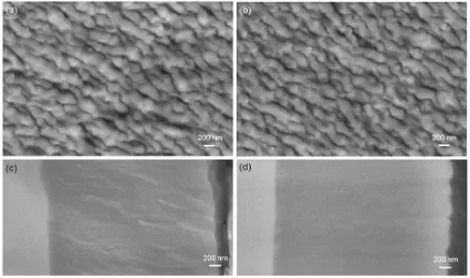
[image:5.595.104.502.375.573.2]Fig. 3 SEM images of the TiN coatings: (a, c) surface and ion-beam polished cross section of the TiN coating grown by 4DC magnetrons; (b, d) surface and ion-beam polished cross section of the TiN grown by 3DC + 1HIPIMS.
Fig. 4 Cross-sectional TEM images and selected area diffraction patterns of the TiN coatings: (a, c) grown by 4DC magnetrons; (b,d) grown by 3DC + 1HIPIMS.
the three DC magnetrons in the 3DC+1HIPIMS deposition can be deduced to be 0.015 µm/min per magnetron, i.e. slightly lower than in the 4DC magnetron sputtering case. Nevertheless, the 3DC +1HIPIMS configuration achieved a reasonably high overall deposition rate of 0.049 µm/min.
Figure 4 shows XTEM observations of the deposited TiN coatings. Figures 4a and 4d are bright field micrographs taken from the outer part of the coatings. Both coatings show void-free dense columnar structures. The rough growth front edges are consistent with the surface waviness (Figures 3a
512
Fig. 5 Cross-sectional TEM images showing a nano scale interfacial film between the sputtered Ti base layer and the steel substrate: (a) grown by 4DC magnetrons; (b) grown by 3DC + 1HIPIMS.
interfacial film can be seen between the base layer and the substrate. The film in each case is approximately 30~50 nm thick, being incoherent with both the substrate and the base layer. It is likely that the interfacial film gave rise to the strong adhesion exhibited by these coatings. In previous research, it has been found that chromium ion etching in cathodic arc mode resulted in the formation of a metal implantation layer on the substrate steel when the substrate bias was lower than -600 V or an intermixed Cr-Fe layer when the bias was higher
[18-19]
. The interfacial films shown in Figure 5 may reflect implanted Ti, however additional experimental study is required to confirm that hypothesis.
Figure 6 shows XRD diagrams of the TiN coatings acquired at the Bragg-Brentano mode. Table 1 shows quantitative measurements of the diffraction peaks. Both coatings exhibit a cubic crystalline structure with strong (220) texture. Note that the 4DC magnetron sputtered TiN shows stronger (111) and (200) diffractions than the 3DC+1HIPIMS deposited coating, indicating a small contribution from randomly orientated grains (consistent to the SAD in Figure 4c). The hybrid deposited TiN shows slightly broader diffraction peaks, indicative of stronger lattice distortion. Table 1 also shows that, the hybrid deposited TiN shows a residual stress of -3.3 GPa, substantially lower than the DC sputtered coating. In
[14]
, Luo et al reported that, in UBM sputtered TiAlN/VN multilayer coatings, the increase of substrate negative bias voltage from -75V to -95 V or higher voltages led to a texture transition from (220) to (111) and a substantial increase in the residual comprehensive stress. In the present study, the low residual stress measured in the hybrid deposited TiN
[image:6.595.330.528.410.553.2]coating should be related to the (220) texture. It can be found that the lattice parameter measured by the Bragg-Brentano geometry is larger than the one measured by the sin2ψ method. This is because the latter is the stress-free value, whereas the former includes the influence of the residual comprehensive stress.
[image:6.595.318.543.592.752.2]Fig. 6 XRD curves of the TiN coatings.
Table 1 Crystalline characteristics and residual stress measurements of the TiN coatings.
Properties 4DC 3DC+1HIPIMS
HK0.025, GPa 34.8 ± 3.8 38.0 ± 5.2 Residual stress, GPa
On (111) -6.0 ± 0.6 -3.3 ± 0.8 On (220) -7.9 ± 1.0 -3.2 ± 1.2
Lattice parameter a0, nm
Stress-free value 0.4231 0.4250
θ-2θ configuration 0.4262 0.4265
Peak broadening (FWHM) degree
β(111) 0.561 0.594
β(200) 0.561 0.594
513
2.3 Tribological properties
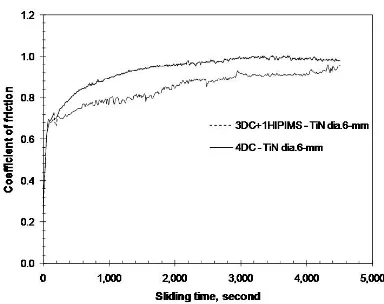
Figure 7 shows typical examples of the friction coefficients measured in the unlubricated sliding wear tests. Both coatings exhibited variation of friction coefficient in the running-in period by starting from a value less than 0.25 and increasing progressively to steady state above 0.9. The running-in process was associated with running-initial abrasive wear of the TiN coatings under the asperity contacts with the counterpart surfaces, leading to the generation of TiN wear particles and their subsequent breaking, adhesive attachment, and the formation of a tribofilm. The steady state friction was governed by the tribofilm. Relevant study about dry sliding tribofilms
[image:7.595.335.527.83.235.2]in similar nitrides can be found in publications [20-21]. Fig. 7 Typical friction curves of the TiN coatings in un-lubricated sliding against a WC-Co counterpart ball.
Table 2 Friction coefficient and wear properties of the TiN coatings.
Wear track dia.
Sliding time
Coefficient of friction
Coefficient of wear
Wear track depth
Wear track width
Ball wear mm sec. × 10-15 m3N-1m-1 µm µm µm
TiN by 4DC
6 4531 0.84 1.5 1.7 214 228
10 6454 0.97 1.2 1.3 192 221
TiN by 3DC+1HIPIMS
6 4499 0.93 1.2 1.4 207 237
10 5404 0.96 2.0 1.6 240 263
The friction and wear properties of the coatings are summarised in Table 2. Four sets of tribotest experiments were carried out. The depths of the wear tracks created on the coatings ranged from 1.3 to 1.7 µm, well within the coating thickness. The average coefficients of friction were 0.84 - 0.97, whereas the specific wear coefficients were of the order of 10-15 m3N-1m-1. The friction and wear properties of the TiN coatings measured in the current experiments are comparable to the results reported in literature under similar wear conditions [22-24]. It has been concluded from the current research that the TiN coating grown by the hybrid 3DC+1HIPIMS deposition has similar tribological properties when compared to the DC magnetron sputtered TiN coating.
3. Conclusions
(1) Using a hybrid 3DC+1HIPIMS deposition, a TiN coating has been grown reactively on steel substrates, to compare with a similar TiN grown by a simple 4DC magnetron sputtering. The hybrid process achieved a reasonably high deposition rate of 0.049 µm /min, being about 23% lower than the rate achieved by the pure 4DC magnetron sputtering. Both coatings exhibited dense columnar structure,
smooth coating surfaces, and NaCl-type cubic crystalline structure with a strong (220) texture.
(2) The HIPIMS incorporation in the magnetron deposition led to an increase of hardness from
HK0.025 34.8 to 38.0 GPa, and simultaneously a
decrease in the magnitude of the residual compressive stress from -6.0 to -3.3 GPa.
(3) The TiN coatings showed friction coefficients in a range of 0.8 - 0.9 and a wear coefficient of the order of 10-15 m3N-1m-1, for both deposition techniques.
(4) Both the techniques produced coatings with excellent adhesion, being attributed to the applied pulsed DC ion etching and the deposition of a metallic Ti base layer combined with the gradual introduction of the reactive nitrogen gas.
References
1 Kouznetsov V, Macak K, Schneider J, Helmersson U, IPetrov I, A
novel pulsed magnetron sputter technique utilizing very high target
power densities[J], Surf Coat Technol, 1999, 122: 290-293.
2 Helmersson U, Lattemann M, Bohlmark J, Ehiasarian AP,
Gudmundsson JT, Ionized physical vapor deposition (IPVD): A review
[image:7.595.99.503.301.421.2]514
3 Sarakinos K, Alami J, Konstantinidis S, High power pulsed magnetron
sputtering: A review on scientific and engineering state of the art[J],
Surf Coat Technol, 2010, 204: 1661-1684.
4 Alami J, Eklund P, Emmerlich J, Wilhelmsson O, Jansson U, Högberg
H, Hultman L, Helmersson U, High-power impulse magnetron
sputtering of Ti–Si–C thin films from a Ti3SiC2 compound target[J],
Thin Solid Films, 2006, 515: 1731–1736.
5 Alami J, Sarakinos K, Mark G, Wuttig M, On the deposition rate in a
high power pulsed magnetron sputtering discharge[J], Appl Phys Lett,
2006, 89: 154104.
6 West G, Kelly P, Barker P, Mishra A, Bradley J, Measurements of
Deposition Rate and Substrate Heating in a HiPIMS Discharge[J],
Plasma Process Polym, 2009, 6: S543-S547.
7 Lundin D, Huo C, Brenning N, Raadu MA, Helmersson U, Deposition
rate loss in high power impulse magnetron sputtering: Understanding
through computational modelling[C], 54th Annual Technical
Conference Proceedings, Chicago, IL April 16–21, 2011, 172-178.
8 Lin J, Sproul WD, Moore JJ, Wu Z, Lee S, Chistyakov R, Abraham B,
Recent advances in modulated pulsed power magnetron sputtering for
surface engineering[J], JOM, 2011, 63: 49-59.
9 Lin J, Sproul WD, Moore JJ, Lee S, Myers S, High rate deposition of
thick CrN and Cr2N coatings using modulated pulse power (MPP)
magnetron sputtering[J], Surf Coat Technol, 2011, 205: 3226-3234.
10 Paulitsch J, Schenkel M, Zufraβ T, Mayrhofer PH, Münz WD,
Structure and properties of high power impulse magnetron sputtering
and DC magnetron sputtering CrN and TiN films deposited in an
industrial scale unit[J], Thin Solid Films, 2010, 518: 5558-5564.
11 Greczynski G, Lu J, Johansson M, Jensen J, Petrov I, Greene JE,
Hultman L, Selection of metal ion irradiation for controlling Ti1xAlxN
alloy growth via hybrid HIPIMS/magnetron co-sputtering[J], Vacuum,
2012, 86: 1036-1040.
12 Yang S, Li X, Cooke KE, Teer DG, A study of TiMoN nano-multilayer
coatings deposited by CFUBMSIP using DC and HIPIMS power[J],
Appl Surf Sci, 2012, 258: 2062-2067.
13 Luo Q, Jones AH, High-precision determination of residual stress of
polycrystalline coatings using optimised XRD-sin2
ψ technique[J], Surf Coat Technol, 2010, 205: 1403-1408.
14 Luo Q, Lewis DB, Hovsepian PE, Münz WD, Transmission electron
microscopy and X-ray diffraction investigation of the microstructure of
nano-scale multilayers TiAlN/VN grown by unbalanced magnetron
deposition[J], J Mater Res, 2004, 19: 1093-1104.
15 Hultman L, Münz WD, Musil J, Kadlec S, Petrov I, Greene JE,
Low-energy (−100 eV) ion irradiation during growth of TiN deposited by
reactive magentron sputtering—effects of ion flux on film
microstructure[J], J Vac Sci Technol, 1991, A9: 434-438.
16 Petrov I, Adibi F, Greene JE, Hultman L, Sundgren JE, Average energy
deposited per atom—a universal parameter for described ion-assisted
film growth[J], Appl Phys Lett, 1993, 63: 36-38.
17 Shaha KP, Pei YT, Chen CQ, Turkin AA, Vainshtein DI, De Hosson
JThM, On the dynamic roughening transition in nanocomposite film
growth[J], Appl Phys Lett, 2009, 95: 223102.
18 Schonjahn C, Bamford M, Donohue LA, Lewis DB, Forder S, Münz
WD, The interface between TiAlN hard coatings and steel substrates
generated by high energetic Cr+ bombardment[J], Surf Coat Technol,
2000, 125: 66-70.
19 Schonjahn C, Donohue LA, Lewis DB, Münz WD, Twesten RD,
Petrov I, Enhanced adhesion through local epitaxy of transition-metal
nitride coatings on ferritic steel promoted by metal ion etching in a
combined cathodic arc/unbalanced magnetron deposition system[J], J
Vac Sci Technol, 2000, A18: 1718-1723.
20 Luo Q, Origin of friction in running-in sliding wear of nitride
coatings[J], Tribo Lett, 2010, 37: 529-539.
21 Luo Q, Zhou Z, Rainforth WM, Bolton M, Effect of tribofilm
formation on the dry sliding friction and wear properties of magnetron
sputtered TiAlCrYN coatings[J], Tribo Lett, 2009, 34: 113-124.
22 Vancoille E, Blanpain B, Ye X, Celis JP, Roos JR, Tribo-oxidation of a
TiN coating sliding against corundum[J], J Mater Res, 1994, 9:
992-998.
23 Huq MZ, Celis JP, Reproducibility of friction and wear results in
ball-on-disc unidirectional sliding tests of TiN-alumina pairings[J]. Wear,
1997, 212: 151-159.
24 Badisch E, Fontalvo GA, Stoiber M, Mitterer C, Tribological behavior
of PACVD TiN coatings in the temperature range up to 500 0C[J], Surf
Coat Technol, 2003, 163–164: 585-590.
Corresponding author: Dr. Quanshun Luo Email: q.luo@shu.ac.uk
Mail address: Materials and Engineering Research Institute, Sheffield Hallam University, Howard Street, Sheffield, S1 1WB, United Kingdom.