Neurofuzzy approach to process parameter selection for
friction surfacing applications
V.I. Vitanov
a,U, I.I. Voutchkov
b, G.M. Bedford
caBuilding 30, School of Industrial and Manufacturing Sciences, Cranfield Uni¨
ersity, Cranfield, Bedfordshire, MK43 OAL, UK
bCEDC, School of Engineering Sciences, Uni¨ersity of Southampton, Highfield, Southampton SO17 1BJ, UK cDepartment of Mechanical and Manufacturing Engineering, Uni¨ersity of Portsmouth, Anglesea Road, Anglesea Building,
Portsmouth PO1 3DJ, UK
Received 31 July 2000; accepted in revised form 1 March 2001
Abstract
Friction surfacing is an advanced manufacturing process, which has been successfully developed and commercialised over the past decade. The process is used for corrosion and wear resistant coatings and for reclamation of worn engineering components. At present, the selection of process parameters for new coating materials or substrate geometries experimentally requires lengthy development work. The major requirement is for the flexibility to enable rapid changes of process parameters in order to develop new applications, with variations of materials and geometries in a cost effective and reliable manner. Further improvement requires development of appropriate mathematical models of the process, which will facilitate the introduction of optimisation techniques for efficient experimental work as well as the introduction of real time feedback adaptive control. This paper considers the use of combined artificial intelligence and modelling techniques. It includes a new frame of a Neurofuzzy-model based Decision Support System ᎏ FricExpert, which is aimed at speeding up the parameter selection process and to assist in obtaining values for cost effective development. Derived models can then be readily used for optimisation techniques, discussed in our earlier work.䊚2001 Elsevier Science B.V. All rights reserved.
w x w x w x
Keywords: X C Friction surfacing; C Hardfacing; Artificial intelligence
1. Introduction
During the past decade the friction surfacing process has become well established with a number of commer-cial applications. However, the existing models explain-ing the major relationships between process parame-ters are still generic. They are based on empirical rules and theoretical assumptions that account for a limited number of cases of current commercial interest. Many of these assumptions are implicit and have not been tested by using appropriate analysis and design of ex-periments. Consequently, there is no method of de-termining the accuracy and sensitivity when changes in
UCorresponding author.
w x
the process parameters are made 1,2 . Research so far
w3᎐8x has revealed that in friction surfacing the
TM Ž . Ž .
mechtrode force F , mechtrode rotation speed N
Ž .
and substrate traverse speed V are of critical impor-tance for the final quality of the coating and bond. In the present study, three state variables were considered that reflect coating quality and, so far have been the subject for optimisation, and in this context a target for process parameter selection. These are coating
thick-Ž . Ž .
ness Ct , coating width Cw , and coating bond strength
ŽCb s.. The optimisation procedure considered in this
study involved:
䢇 appropriate set-up for in-process precision mea-surement of temperature, torque, bonding time, spindle rotation speed and force;
0257-8972r01r$ - see front matter䊚2001 Elsevier Science B.V. All rights reserved.
Ž .
( )
V.I. Vitano¨et al.rSurface and Coatings Technology 140 2001 256᎐262 257
䢇 estimation of correlation between process parame-ters V, F, N, and coating quality state variables Cb s,Ct and Cw; and
䢇 development of a FricExpert decision support
sys-Ž .
tem to utilise force F , mechtrode rotation speed
ŽN., and substrate traverse speed ŽV., as well as
Ž . Ž .
temperature T , torque M , and bonding time
Žtb., to achieve the desired values for coating
thick-Ž . Ž .
ness Ct , coating width Cw , and bond strength
ŽCb s..
2. Experimental method
2.1. Materials and geometry
The importance of torque, temperature and bonding time for obtaining coatings with desirable quality
w x
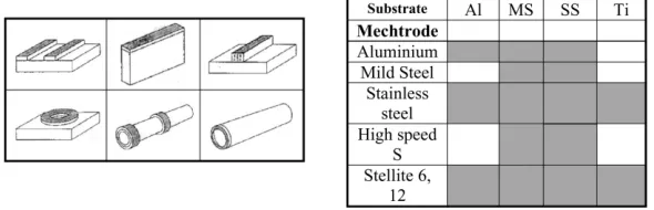
parameters is identified in 8 . The significance of these factors has also been confirmed through performing more than 1300 friction surfacing screening experi-ments in the surface engineering laboratory at the University of Portsmouth, using different materials and geometries for the mechtrodes and substrates, Fig. 1. Several different types of stainless steel mechtrodes
Ž .
were used 303, 304, 316, 416, 431 , ranging in diameter from 3 to 8 mm.
2.2. Temperature and bonding time
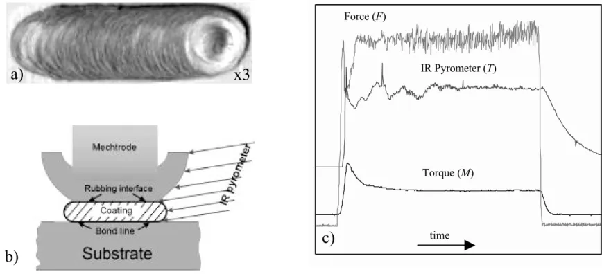
Because of the nature of the in-process measure-ments of the coating and the mechtrodercoatingr sub-strate interface temperatures, a non-contact IR pyro-meter, manufactured by IMPAC Electronic, was used. The accuracy of measurement is approximately 0.3% of the measured value. Two lenses were used, with focus distances of 80 and 250 mm, with a spot size diameter of 0.3 and 0.5 mm, respectively. The sampling rate was 103 measurementsrs enabling accurate determination of bonding times for each coating cycle. Fig. 2 shows a cross-section of the deposit and directions of
tempera-ture measurement using the IR pyrometer. The experi-mental results were automatically recorded into a pur-pose-designed database. This approach significantly re-duced set-up time and running costs for the friction surfacing experiments.
Bonding time is defined as the duration when the
Ž .
diameter of the heat generation area bonding area passes entirely over a given point on the substrate. As shown in Fig. 3a, the bonding area is less than the surface specified by the mechtrode diameter. It has been estimated that the axial diameter of the bonding area is approximately 6r7 of its tangential diameter, which is equal to the mechtrode diameter, so that
dbs0.875=Md,
where Md is the mechtrode diameter. The bonding time is then defined as:
0.875Md tbs V ,
whereV is the traverse speed.
Fig. 3b shows the bonding time for the most used mechtrode diameters and substrate speeds.
Longer bonding time would logically mean better bonding, since there is more time for the process to occur and complete. However, the heat energy flux, which is generated during this bonding time, has to be balanced, because if too much, it might have a negative effect on the quality of coating. The easiest way to control the energy flux is by altering the bonding time. Furthermore, experiments have shown that low values of V, are difficult to achieve.
2.3. Torque and force
Torque was measured using a piezoelectric sensor manufactured by Kistler Instruments with a measuring range for force of 0᎐14 000 N and "20 000 Ncm for torque. The sensitivity of the equipment is pCrNs
[image:2.595.148.443.623.718.2]y2.03 and pCrNcms1.66. The acquired sets of data were stored in a database by using multifunction IrO
Ž . Ž . Ž .
Fig. 2. a Plan view of coating, b temperature measurements, and c process parameters.
Ž .
board AT-MIO-16E-10 from National Instruments
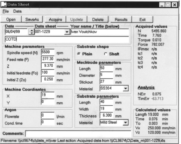
capable of data acquisition at a rate of 100 000 samples sy1. LabVIEW application software was used to
auto-mate the data acquisition process. Examples of data acquisition and condition monitoring software are shown in Fig. 4.
2.4. Bond metallography and strength
Cross-sections of coatings were examined in the as-polished state to determine the quality and width of the bond, and the amount of unbonded undercut at the edges of the coating. Bond strengths were determined by a simple push-off test, although more sophisticated testing based on a fracture mechanics approach is
currently being developed. The metallography of a cross-section of a well-formed friction surfaced coating is shown as in Fig. 5a,b. This clearly illustrates the undercut at the edge which is an inherent feature of the process. The optimisation process essentially ex-tends the width of good bond and minimises the under-cut at the edges. Materials used in these illustrations are 316 stainless steel coatings on mild steel.
3. General concept of FricExpert decision support system
The development process of the FricExpert Decision Support System comprises the following key stages:
Ž . Ž .
[image:3.595.83.517.75.273.2] [image:3.595.293.521.505.689.2]( )
[image:4.595.140.453.68.317.2]V.I. Vitano¨et al.rSurface and Coatings Technology 140 2001 256᎐262 259
Fig. 4. Screen shot of data collection and storage software.
䢇 establishment of the relationships between control-lable, observable and quality parameters; and 䢇 development of the inference mechanism.
3.1. Relationship between process parameters and coating state¨ariables
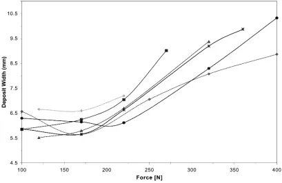
Fig. 6 is a schematic of the adopted experimental approach and indicates dependencies between process parameters V, F and N, and coating state variables Cb s, Ct and Cw. To initially establish these relation-ships the bonding time, torque and temperature have been measured followed by regression and neural
net-work analysis to confirm the existence of relationships and to establish the types of function. Fig. 7 shows an example of the effect of mechtrode feed rate on the deposit width. Similar relationships have been es-tablished for the rest of the process parameters and coating state variables. The same procedure has been repeated for M, tb and T, and coating state variables Cb s,Ct and Cw. But this time M, tb and T have been regarded as dependent variables. As a result of this analysis, functional relationships between major parameters and state variables have been obtained as shown in Fig. 8. These results form a foundation for reverse process designs. On the basis of detailed mea-surements the following rules were derived:
Ž . Ž . Ž .
[image:4.595.70.518.547.719.2]Fig. 6. Schematic representation of experimentally established relationships between controllable, observable and quality parameters in the friction surfacing process.
䢇 increasing force increases proportionally the bond strength;
䢇 increasing force reduces proportionally the coating thickness;
䢇 increasing traverse speed reduces proportionally the coating thickness;
䢇 increasing traverse speed has a second order rela-tionship to the bond strength;
䢇 low values of V make the coating thicker;
䢇 an increase of coating thickness weakens the bond;
䢇 high traverse speed reduces the coating thickness, and the bonding time, resulting in reduced bond strength; and
䢇 the traverse speed has its optimum value around the centre of gravity of the trapezium.
Bond quality is also related to input parameters.
䢇 The higher the mechtrode force, the less the under-cut.
䢇 The faster the substrate movement the less the bonded area, the more the undercut.
3.2. Inference mechanism
The experimental results have been transformed into fuzzy membership functions and the above principles have been developed further into fuzzy logic rules
[image:5.595.97.506.453.719.2]( )
[image:6.595.115.474.67.351.2]V.I. Vitano¨et al.rSurface and Coatings Technology 140 2001 256᎐262 261
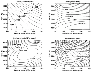
Fig. 8. Functional relationships between major process parameters and coating state variables.
w9᎐13 that are built into FricExpert’s inference engine.x
In the current approach, presented schematically in Fig. 9, the decision support module selects appropriate values of the process parameters, traverse speed and force in order to obtain a desired value for the coating thickness. The bell-shaped curves represent the
mem-bership functions. When a value for the force and speed is set, its membership is determined and passed onto the logic rules relating it to the thickness. Actual value for thickness is then obtained using logical multi-plication and defuzzyfication procedures.
[image:6.595.88.506.480.716.2]Using the knowledge of previously recorded runs
Žnow more than 1900 , the system is capable of giving.
expert advice for the next set of experiments, in order to meet various requirements for various quality vari-ables. The value of this system is in reducing the lead time and, hence, cost for determining the optimum parameters for a given coating material on a given substrate geometry. This is an important feature when developing the process for new applications because the optimal process parameters depend on the thermal system, which will vary when materials, mechtrode di-ameters and substrate geometries are changed. The range of commercial applications of the friction surfac-ing process currently includes the manufacture of ma-chine knives for the food and pharmaceutical process-ingrpackaging industries. Other applications include hardfacing of valve seats with stellite, the repair and manufacture of parts for the gas turbine industry, notably gas turbine blades, and various types of tooling such as punches and drills.
4. Conclusions
1. Measurement and data analysis techniques have been successfully developed for the friction surfac-ing process.
2. The introduction of the FricExpert Decision Sup-port System has shown to be promising for process parameter selection.
3. Fuzzy rules and membership functions have been established between quality state variables and process parameters, such that they allow for re-verse engineering of the optimum friction surfacing process parameters.
References
w x1 E.D. Nicholas, W.M. Thomas, Metal deposition by friction
Ž .
welding, Welding J. August 1986 17᎐27.
w x2 T. Shinoda, Q. Li, Y. Katoh, T. Yashiro, Effect of process parameters during friction coating on properties of
non-dilu-Ž . non-dilu-Ž .
tion coating layers, Surf. Eng. 14 3 1998 211᎐216.
w x3 G.M. Bedford, Friction surfacing for wear application, Metals
Ž . Ž .
Mater. 6 11 1990 702᎐705.
w x4 G.M. Bedford, A. Davies, J.R. Sharp, Micro-friction surfacing in the manufacture and repair of gas turbine blades, Third International Charles Parsons Turbine Conference, Newcastle,
Ž1995 683. ᎐693.
w x5 G.M. Bedford, R.P. Sharp, B.J. Wilson, L.G. Elias, Production of friction components using steel MMCs produced by the
Ž . Ž .
osprey process, Surf. Eng. 10 2 1994 118᎐122.
w x6 G.M. Bedford, V.I. Vitanov, I.I. Voutchkov, Decision support
Ž .
system for the frictec friction surfacing process, Proceedings of the Thirteenth National Conference on Manufacturing,
Ž .
Glasgow, UK, 9᎐11 September 1997, 1997 580᎐584.
w x7 G.M. Bedford, L.J. Ward, P.J. Tooley, B.J. Wilson, R.J. Sharp, Large scale friction surfacing, EUROMAT’95, Proceedings of the Fourth European Conference on Advanced Materials and
Ž .
Processes, Italy, Sept. 1995, 1995 441᎐444.
w x8 I.I. Voutchkov, V.I. Vitanov, G.M. Bedford, Neurofuzzy model-based selection of process parameters for friction surfac-ing applications, Proceedsurfac-ings of the Thirteenth National Con-ference on Manufacturing, Glasgow, UK, 9᎐11 September 1997,
Ž1997 491. ᎐495.
w x9 S. Chui, Fuzzy model identification based on cluster estimation,
Ž . Ž .
J. Intelligent Fuzzy Syst. 2 3 1994 .
w x10 I. Graham, P. Jones, Expert Systems Knowledge, Uncertainty and Decision, Chapman and Hall Computing, 1988.
w x11 M. Musen, Automated Generation of Model-Based Knowledge-Acquisition Tools, Pitman, London, 1989.
w x12 S. Padney, Computer aided process planning ᎏ an expert system approach, computer technology in welding, Proceedings of the Sixth TWI International Conference, 9᎐12 June, 1996,
Ž1996 ..