Abstract— Energy is pivotal to almost all of the challenges and opportunities in sub-Saharan Africa. However, the grid-based power generation capacity is grossly insufficient and unreliable to meet the increasingly growing energy demands in the region. Low incomes and exorbitant cost of energy make energy unaffordable for citizens, despite the availability of renewable resources. Low-income countries can readily harness the cost-effectiveness and the availability advantages offered by free energy option to meet the continuously growing energy demand in the region, without any adverse effect on the environment. In this paper, we designed and developed an affordable neodymium-based free energy generator that operates continuously without depending on any external source. The repulsive force between the neodymium magnets produce a torque which serves as a prime mover for rotor blades. The energy generated is transferred to a charge controller connected to the battery bank. The battery supplies the inverter with a direct current (DC) input voltage for electricity generation in alternating current (AC) form. The generated electrical power is distributed to consumers. The results of prototype testing shows that this energy option is affordable and it is not subject to climatic conditions. Therefore, this alternative energy source is a potential off-grid solution to the energy challenge in sub-Saharan Africa.
Index Terms— free energy generator, renewable energy, sustainable development, neodymium magnets, inverter
I. INTRODUCTION
CCESS to sustainable energy has a direct relationship with job creation, industrialization, health, climate change, food production, and consequently economic growth. However, more than one billion people in different parts of the world still lack basic access to modern energy services [1]. According to Africa Energy Outlook Report [2], more than 620 million people, representing two-thirds of the population in the region, still live without electricity. The mean electricity consumption per capita cannot even keep a single 50-watt light bulb on. Inability of grid-based power generation capacity to sufficiently and reliably meet the increasingly growing energy demands has encouraged large-scale ownership of expensive generators that run on
Manuscript received February 07, 2017; revised April 13, 2017.
A. U. Adoghe, I. O. Oyinlola, S. I. Popoola, and AAA. Atayero, Department of Electrical and Information Engineering,
Covenant University, Ota, Nigeria.
[email protected], [email protected], [email protected]
fossil fuels. The recent increasing concentrations of greenhouse gases in the atmosphere is a by-product of this problem. Therefore, timely attainment of sustainable development in sub-Saharan Africa is largely hinged on increasing access to affordable, reliable, and clean energy for all.
Fossil fuel is the most popular primary energy source for electricity generation in sub-Saharan Africa. The total on-grid power generation capacity comes from coal (mainly South Africa), hydro, oil, and gas (mainly Nigeria) [2]. Long over-dependence on fossil fuel for power generation has contributed largely to climate change, which is an adverse of effect global warming. Energy accounts for about 60 percent of total greenhouse gas emitted worldwide.
There is an ongoing drive to significantly increase the proportion of renewable energy in the global energy mix [3]. Renewable energy is a form of alternative energy source that can be conserved and can continuously replenish without any adverse effect on the planet. Common renewable energy sources in sub-Saharan Africa include solar, wind, hydro, and bio-fuels. Out of all, solar energy has proven to be the most promising owing to its unparalleled potential for power generation [4-6]. Sub-Saharan Africa has unlimited renewable resources but the large-scale conversion of these abundant resources into usable form has been the challenge. Home users and small companies have started exploiting alternative energy to meet their energy needs. Solar energy seems to be receiving more patronage but its output performance is subject to unpredictable weather condition and limitations of geographical locations [7]. The durability of photovoltaic panels is not satisfactory enough for sustainability. In addition, power generation using solar energy tends to be more cost-intensive to run on long term. Therefore, low incomes and exorbitant cost of energy make energy unaffordable for citizens, despite the availability of resources.
Off-grid power generation is an effective energy solution to curtailing business downtime that unreliable power grid has introduced. This will help to revamp the current economic decline. Low-income countries can readily harness the cost-effectiveness and the availability advantages offered by free energy option [8, 9] to meet continuously growing energy demand in the region, without any adverse effect on the environment [10]. Neodymium Magnetically-Induced Free Energy Generator (NMIFEG) is a form of „free energy‟ source since no external force is required to drive the system. It operates purely on the
Free Energy Generation using Neodymium
Magnets: An Off-Grid Sustainable Energy
Solution for Sub-Saharan Africa
Anthony U. Adoghe, Member, IAENG, Ifeoluwa O. Oyinlola, Segun I. Popoola, Member, IAENG, Aderemi A. Atayero, Member, IAENG
principle of magnetic field induction and it is sustainable for households and small businesses in sub-Saharan Africa.
In this paper, we developed a NMIFEG that uses neodymium magnetic field that exists between similar magnetic poles to generate electricity. The magnets allow NMIFEG to operate continuously without depending on any external source. It is a complex design that involves the interconnection of diverse components of power generation and distribution. The repulsive force produce a torque which serves as a prime mover for rotor blades. The energy generated is transferred to a charge controller connected to the battery bank. The battery supplies the inverter with a direct current (DC) input voltage for electricity generation in alternating current (AC) form. The generated electrical power is distributed to consumers.
The rest of the paper is summarized as follows: Section II identifies and explains the functionalities of each of the components involved in the system design of NMIFEG; Section III presents the prototype implementation of the design; Section IV gives the test procedures and discusses the results obtained; Section V summarizes the findings of the work.
II. COMPONENTS OF FREE ENERGY GENERATOR AND INVERTER SYSTEM
The entire system design include the free energy generator, the charge controller, and the inverter system as shown in Figure 1.
[image:2.595.52.289.550.605.2]The free energy generator comprises of an arrangement of neodymium magnets to produce the energy needed by the output load. The neodymium magnets are strategically placed on base plates with their like poles facing each other. Thus, a repulsive force is generated between the poles, causing the shaft of the DC motor to rotate continuously. This rotation generates electromagnetic field and electric current is induced in the conductor. The induced energy is supplied to the load (a 12-volt battery) via the charge controller. The battery is charged and the charge voltage is regulated by the controller. The inverter system converts the input DC voltage into an AC voltage.
Figure 1: Block Diagram of the Free Energy Generator and Inverter System
A. Neodymium Magnets
Neodymium magnets are the most widely used type of rare-earth magnets. They are permanent magnets made from alloy of neodymium alloy, iron and boron to form the Nd2Fe14B tetragonal crystalline structure. They are the
strongest type of permanent magnet commercially available and have replaced other types of magnet in the many application areas such as motors in cordless tools, hard disk drives and magnetic fasteners. There are two rare earth magnets: neodymium iron boron and samarium cobalt. Although neodymium iron boron is similar to samarium cobalt, the former is more easily oxidized and does not have the same temperature resistance.
Neodymium iron boron is mechanically stronger than samarium cobalt magnets, and it is also weightier than ceramic or alnico. However, it produces the highest amount of flux per unit of volume or mass, making it more economical for a number of applications. Alnico is the trade name for an alloy used to make high energy permanent magnets; it contains aluminum, iron, nickel with either cobalt, copper or titanium. NdFeB has a very high energy product and a very high coercive force. The temperature stability is quite moderate. This work utilized this type of magnet because of their strength. Their long lifespan is an advantage to keep the rotor rotating continuously over a very long period.
B. DC Motor
A 30-Volt, 30-Amps brushless DC motor was employed for this work. It has a power rating of 1 horsepower, and a mechanical rotation speed of 300 revolution per minute. The DC motor converts the mechanical rotation of the blades, caused by the repulsive force between the magnets, into electrical energy. As the neodymium magnets rotate the shaft of the motor, the rotor of the motor rotates and a magnetic field is created within the motor by the stator, thereby causing a current to flow through a coil.
When the rotor wire loop rotates in the magnetic field produced by the stator, it produces a magnetic flux that passes through the loop and generates a voltage, which is induced across the loop terminals. The generated voltage is collected by the two segments of the commutator and delivered to the set of stationary brushes, which are connected to the terminals of the motor. When the loop takes a 180 degree turn, the magnetic flux in the loop is passed from a negative maximum to a positive maximum. At this other end, the connection of the commutator segments and the brushes are reversed. This consequently reverses the connections between the motor terminals and the wire loop terminals.
On taking another 180 degree turn back, the magnetic flux in the loop passes from a positive maximum to a negative maximum. When the loop reaches the initial position, the connections of the commutator segments and the brushes are reversed again, thereby reversing the connection between the motor terminals and the wire loop terminals. This cycle is repeated as long as the rotor rotates, causing the polarity of the voltage induced to alternate continuously (AC voltage).
The stator is the fixed part of the motor where the rotor turns. The stator has a pair of permanent magnets that align so that the poles of opposite polarities face each other.
C. Single-Pole Double-Throw Relay
Closed (NC). The NC contact is connected to the C contact when the relay is not excited. As soon as the coil is energized, the NO contact becomes connected.
D. Charge Controller
A charge controller regulates the rate at which electric current is supplied to or drawn from the DC batteries [11]. It prevents overcharging and overvoltage that can affect the
optimal performance of the battery or shorten its lifespan. It may also prevent deep discharging, depending on the battery technology. A charge controller may either be a stand-alone device that controls the circuitry integrated within a battery pack, or a battery recharger. The device stops the charging process when the set voltage limit is reached, and starts when the battery voltage fall below a preset value.
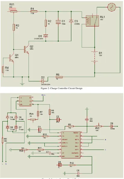
[image:3.595.93.505.148.744.2]Figure 2: Charge Controller Circuit Design
The circuit design of the charge controller is shown in Figure 2. It was designed to control the charging of the 12V DC battery. When the 12V DC battery is full, an electrical signal is sent from the positive side of battery to the coil to open the circuit. The green LED comes on to signify that the battery is full. On the other hand, when the battery level drops, an electrical signal comes from the charging source into the coil, activating the charging process. This causes the common terminal to close the NC terminal, which is open at the time, and opens the NO terminal, which is closed at the time. The yellow LED signifies that the circuit is active when switched on. The electrolytic capacitor smoothens the signal and then passes it through a diode to a combination of current limiting resistors (the diode ensures that the signal maintains the forward direction). The current signal is amplified by Darlington transistor. The amplified current flows through the negative side of the battery and charges it till it is fully charged.
E. Inverter System
[image:4.595.311.543.134.203.2]Power inverters are devices that convert electrical energy from DC to AC. There are three types of inverters: square wave inverters; modified square wave inverters; and true sine wave inverters The inverter in this work is a pure sine wave 2000 VA (2 kVA) inverter. It converts DC to AC power by switching the DC input voltage (or current) in a pre-determined sequence so as to generate AC voltage (or current) output using the Pulse-Width Modulation (PWM) technique. The input DC voltage is received from the 12 DCV battery and sent to the oscillator board which consists of the control (4N35 and SG3524N) and switching circuits (two IR2110 ICs). The oscillator output is sent to the transformer as shown in Figure 3. The transformer steps up the voltage to required 220 V for household consumption.
Figure 4: Circuit Configuration of the H-Bridge
The switching part of the inverter consists of the H-Bridge and the switching circuit. The switching circuit makes use of two IRF2110 MOSFET switches to level transition between the PWM signals and voltages to forward bias high side N-channel MOSFETS in the H-Bridge. In order to generate a sine wave, a positive and a negative voltage are required to be connected across the load. This is done by using four MOSFET switches in an H-bridge configuration shown in Figure 4. To reduce power loss and to have a higher switching frequency, N-channel MOSFETs are chosen as switches in the bridge.
F. Centered-Tap Step-Up Transformer
For the inverter to be useful in handling appliances of AC power ratings higher than what is available within the circuit, there is a need for a step-up transformer. The
center-tapped step-up transformer increases the circuit voltage to match the actual AC requirements of devices. The transformer must be able to handle the inverter wattage output. Since the design of this work is for a 2 KVA inverter system, a 2 KVA-rated transformer was considered appropriate.
Figure 5: Operational Processes of the System
III. DESIGN METHODOLOGY AND PROTOTYPE IMPLEMENTATION
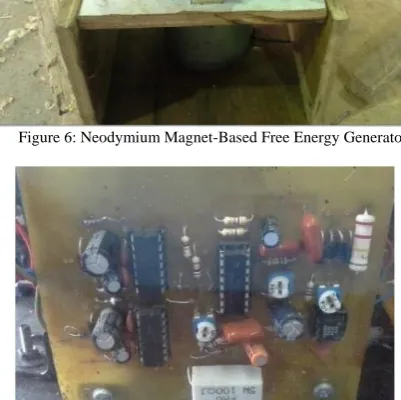
The free energy generator was placed in a wooden casing and the baseplate has six neodymium magnets. The rotor part attached is attached to the wood which has three blades and three neodymium magnets as shown in Figure 6. The magnets were arranged such that the like poles of the magnets on the rotor blades and the like poles of the magnets on the base plate were facing each other to allow a strong repulsive force to be generated. Figure 5 shows the stages of operational processes of the system.
[image:4.595.321.532.399.598.2]The charge controller was soldered onto a Vero board and the casing was an open casing with a transparent plastic at the back as shown in Figure 7 and Figure 10.
[image:4.595.55.282.451.589.2]Figure 6: Neodymium Magnet-Based Free Energy Generator
Figure 7: Implementation of Oscillator Circuit Design
[image:4.595.325.526.486.686.2]wooden part of the casing. A fan was attached to cool the heat sinks attached to the MOSFET circuit as shown in Figure 9. Other necessary accessories included in the casing are the analog voltmeter, an LED to indicate when the inverter was switched on, an output socket, and the power switch.
[image:5.595.318.536.197.400.2]Figure 8: Side View of the Inverter System showing the Oscillator Circuit, the Transformer and the H-Bridge
[image:5.595.55.286.337.491.2]Figure 9: Side View of the Inverter System showing DC Fan and Battery Terminals
Figure 10: Charge Controller Circuit
IV. SYSTEM TESTING AND RESULTS
An experiment was carried out to test the performance of the inverter system. The PWM inverter produced an AC pure sine wave with an output power of 2 KVA and supplied an output voltage of 220 V to the load as desired. With the aid of an oscilloscope, the output of the oscillating circuit was confirmed to be a pure sine wave as clearly depicted in Figure 11 and Figure 12.
Figure 11: Square Waveform before Rectification
Figure 12: Sine Waveform after Rectification
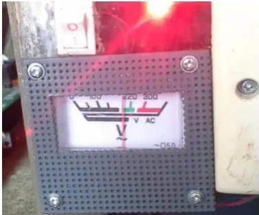
For the no-load test, a rechargeable battery was connected to the inverter circuit. The positive terminal of the battery was connected to the centered-tap of the inverter‟s transformer while the negative terminal of the battery was connected to the overall ground of the inverter circuit. When the inverter was switched on, a loud humming noise from the transformer was observed which indicated that the output voltage was too high. A screwdriver was used to adjust the pulse width output by turning the variable resistor in the control circuit. The exact value of the output voltage was determined by inserting the terminals of a digital voltmeter into the socket. In this way, the output voltage was reduced to 220V as shown in Figure 13.
[image:5.595.55.285.519.674.2]A bulb was connected to the output socket and no unusual event was recorded during the load test.
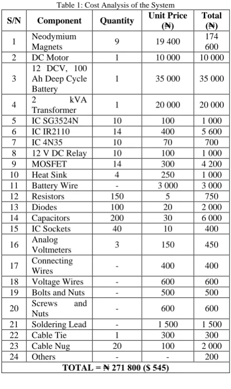
[image:5.595.332.521.614.770.2]Table 1: Cost Analysis of the System
S/N Component Quantity Unit Price (₦) Total (₦) 1 Neodymium
Magnets 9 19 400
174 600
2 DC Motor 1 10 000 10 000
3
12 DCV, 100 Ah Deep Cycle Battery
1 35 000 35 000
4 2 kVA
Transformer 1 20 000 20 000
5 IC SG3524N 10 100 1 000
6 IC IR2110 14 400 5 600
7 IC 4N35 10 70 700
8 12 V DC Relay 10 100 1 000
9 MOSFET 14 300 4 200
10 Heat Sink 4 250 1 000
11 Battery Wire - 3 000 3 000
12 Resistors 150 5 750
13 Diodes 100 20 2 000
14 Capacitors 200 30 6 000
15 IC Sockets 40 10 400
16 Analog
Voltmeters 3 150 450
17 Connecting
Wires - 400 400
18 Voltage Wires - 600 600
19 Bolts and Nuts - 500 500
20 Screws and
Nuts - 600 600
21 Soldering Lead - 1 500 1 500
22 Cable Tie 1 300 300
23 Cable Nug 20 100 2 000
24 Others - - 200
TOTAL = ₦ 271 800 ($ 545)
V. CONCLUSION
Off-grid power generation is an effective solution to curtailing business downtime that unreliable power grid has introduced. Free energy generator offers great advantages of cost-effectiveness and availability for the underserved population of sub-Saharan Africa to meet their energy needs.
This work has successfully demonstrated the viability of neodymium-based free energy generation for sustainable development in the region. A neodymium magnetic generator was designed and implemented generate electrical energy and to charge a 12 VDC deep-cycle battery. The magnetic generator converts the mechanical energy gotten from the motion of magnets moving under repulsive force, into electrical energy using a 30 VDC motor. The DC output was converted to AC voltage using a 2 KVA, 220 V inverter system. A charge controller was utilized for over-charging protection.
The free energy generator has proven to be cheap. The overall cost of the neodymium-based free energy generator, the inverter system, and the charge controller was estimated at $545. This option is affordable and it is not subject to climatic conditions. Therefore, this alternative energy source is a potential off-grid solution to the energy challenge in sub-Saharan Africa.
REFERENCES
[1] Sustainable Energy for All Initiatives. Available at:
http://www.se4all.org/
[2] International Energy Agency, “Africa Energy Outlook”, 2014.
Available at:
https://www.iea.org/publications/freepublications/publication/WEO20 14_AfricaEnergyOutlook.pdf
[3] United Nations, “Sustainable Development Goal 7”. Available at:
http://www.un.org/sustainabledevelopment/energy/
[4] S. O. Oyedepo, “Towards achieving energy for sustainable development in Nigeria”, Renewable and Sustainable Energy Reviews, Volume 34, June 2014, Pages 255-272.
[5] S. O. Oyedepo, “On energy for sustainable development in Nigeria”, Renewable and Sustainable Energy Reviews, Volume 16, Issue 5, June 2012, Pages 2583-2598
[6] V. O. Matthews, A. A. Atayero, and S. I. Popoola, "Development of a Solar Photovoltaic Vulcanizing Machine towards Extreme Poverty Eradication in Africa," Lecture Notes in Engineering and Computer Science: Proceedings of The World Congress on Engineering and Computer Science 2016, 19-21 October, 2016, San Francisco, USA, pp315-320.
[7] M. E. Emtere and M. L. Akinyemi, “Weather Effect on Photovoltaic Module Adaptation in Coastal Areas”, International Journal of Renewable Energy Resources 5 (3), 2015, pp. 821-825.
[8] E. Elizalde and A. Romeo, “Essentials of the Casimir Effects and its Computation”, American Journal of Physics, 59, 1991, pp. 771. [9] G. Plunien, B. Muller, and W. Greiner, “The Casimir Efect”, Phys.
Rep. 134, 1986, pp. 87-193.
[10] M. E. Emetere, U. Okoro, B. Etete, G. Okunbor, “Free Energy Option and its Relevance to Improve Domestic Energy Demands in Southern Nigeria”, Energy Reports 2 (2016), pp. 229-236.