Abstract—Drilling composite materials is a frequently practiced machining process during assembling in various industries such as automotive and aerospace. However, drilling of glass fiber reinforced plastic (GFRP) composites is significantly affected by damage tendency of these materials under cutting forces such as thrust force and torque. The aim of this paper is to investigate the influence of the various cutting parameters such as cutting speed and feed rate; subsequently also to study the influence of number of layers on delamination produced while drilling a GFRP composite. A plan of experiments, based on Taguchi techniques, was instituted considering drilling with prefixed cutting parameters in a hand lay-up GFRP material. The damage induced associated with drilling GFRP composites were measured. Moreover, Analysis of Variance (ANOVA) was performed to obtain minimization of delamination influenced by drilling parameters and number layers. The optimum drilling factor combination was obtained by using the analysis of signal-to-noise ratio. The conclusion revealed that feed rate was the most influential factor on the delamination. The best results of the delamination were obtained with composites with greater number of layers at lower cutting speeds and feed rates.
Index Terms—Analysis of variance, Delamination, Design Optimization, Drilling, Glass fiber reinforced plastic composites, Taguchi Method
I. INTRODUCTION
Since the past two decades, the use of composite materials like glass fiber reinforced plastic (GFRP) has proliferated and is still continually increasing in various significant industries such as automotive, aircraft, aerospace and naval. This spike in their application is largely due to high corrosion resistance, high specific strength (Stiffness), light weight construction, high fatigue strength, low thermal conductivity and resistance to chemical or microbiological attacks as compared to the metallic materials.
Owing to the inhomogeneous and anisotropic nature of the composite materials, their machining behavior differs in many
Manuscript received Sep 14, 2016..
Vimanyu Chadha is with the Delhi Technological University, New Delhi-110042, India(phone: +91-9871369354; e-mail: vimanyuchadha@gmail.com).
Sanchay Gupta is with the Delhi Technological University, New Delhi-110042, India (e-mail: sanchay2303@gmail.com)
aspects from the machining of traditional materials. Drilling is the one of the most common secondary machining process; and any defect might lead to rejection of that part. The economic impact of this is significant considering the value associated with the part when it reaches the assembly stage [1]. Different investigators have studied that delamination is a dangerous problem associated with drilling fiber-reinforced composite materials. Delamination also reduces the structural integrity of the materials, which results in poor assembly tolerance and has potential for long term performance deterioration [2]. Drilling induced delamination occurs both at the entrance and the exit planes of the workpiece. The delamination damage caused by the tool geometry has been recognized as one of the major problem during drilling. E. Kilickap [3]investigated the influence of cutting parameters, cutting speed and feed rate, and point angle on delamination when drilling of hand lay-up GFRP composites. Their study’s main objective was to find the important factors and combination of factors to achieve minimum delamination. The analysis of experimental results was carried out using Taguchi’s orthogonal array and analysis of variance (ANOVA). Results showed that the feed rate is the main cutting parameter and that the damage increased with both cutting parameters. Hence, low feed rates provided minimum damage. The results also showed that a drill of lesser point angle produced less damage.
C.C. Tsao et al. [4] predicted and evaluated delamination factor in use of twist drill, candle stick and saw drill. They used Taguchi’s method and analysis of variance (ANOVA) for analysis of experimental results. An ultrasonic C-scan machine was used to examine the delamination of carbon fiber reinforced plastic (CFRP) laminate. They conducted the experiments to study the delamination factor under various cutting conditions. The results showed that feed rate and drill diameter were the most significant parameters. The results also showed that the candle stick drill and saw drill caused a smaller delamination factor than twist drill. Using multi-variable linear regression, a correlation between feed rate, spindle speed and drill diameter with the delamination observed was established, and the correlation was compared with experimental results.
Davim et al. [5] evaluated the cutting parameters (cutting speed and feed rate) and the influence of the matrix under specific cutting force, delamination factor and surface
Optimization of Cutting Parameters on
Delamination Using Taguchi Method during
Drilling of GFRP Composites
lay-up. A piezoelectric dynamometer was used to acquire the values of torque and thrust force. Taguchi’s method was used and the treatment of experimental results was based on analysis of variance (ANOVA). The results showed that the specific cutting force decreased with both cutting parameters. The delamination factor increased with both cutting parameters. The feed rate had the highest physical as well as statistical influence on the delamination factor in both composite materials. The surface roughness increases with the feed rate and decreases with the cutting speed. The cutting speed has the highest physical as well as statistical influence on the surface roughness for both the composite materials. Davim et al. [6]studied the cutting parameters (cutting speed and feed rate) under specific cutting pressure, thrust force, damage and surface roughness in glass fiber-reinforced plastics (GFRP). Taguchi’s method with analysis of variance (ANOVA) was applied on the experimental data which was established considering drilling with prefixed cutting parameters in a hand lay-up GFRP material. A piezoelectric dynamometer with a load amplifier was used to measure the torque and the thrust force. The results showed that the specific cutting pressure decreased with feed rate and the thrust force increased with the feed rate. The feed rate had the greatest influence on the on the specific cutting pressure and thrust force. The damage increased with both cutting parameters. The surface roughness increased with the feed rate and decreased with the cutting speed.
Palanikumar et al. [2] studies delamination associated with drilling using experimental design approach. The experiments were conducted by using two different cutting tools which were high speed steel made twist drill and 4 flute cutter. Empirical models were developed for predicting delamination factor in drilling GFRP composites. Regression analysis and analysis of variance (ANOVA) were used for analysis. The results showed that feed rate was the dominant factor affecting the delamination in drilling GFRP composites. 4 flute end mill cutters showed better results than twist drill in drilling of GFRP composites. Lower feed rate was preferred for achieving minimal delamination.
Khashaba [1] conducted experiments on delamination in drilling GFR-thermoset composites. He had investigated the influence of drill and material variables on torque, thrust force and delamination in drilling GFRP composites. After extensive studies on different E-glass composites, he developed a simple accurate technique to measure the delamination size.
The primary objective of the present work is to investigate the influence of the drilling factors such as cutting speed and feed rate in drilling of GFRP composites. Three different combination of layers were tried for experimentation. Based on Taguchi’s method design and ANOVA, the analysis of experimental results is carried out using main effect and interaction effect graphs.
II.MATERIALS AND EXPERIMENTAL TECHNIQUE
A.Means and Materials
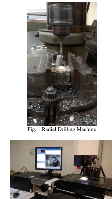
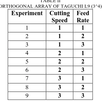
[image:2.612.339.521.248.570.2]In this study, the composite material used in the experiments (reinforced with 50% of E-glass fibers) are made with an unsaturated polyester matrix. Three different type of workpiece specimen i.e. 2 layers, 3 layers and 4 layers of same dimension of 50 x 50 mm were manufactured. The drilling test were conducted on a HMT Radial Drilling machine (Fig. 1). Drills used throughout the test were of 6 mm with High Speed Steel (HSS), had a helix angle of 32°. All tests were run without coolant at cutting speeds of 16, 22 and 32 m/min and feed rates of 0.2, 0.3 and 0.5 mm/rev. The damage around the holes was measured using a SIPCON’s Vision Inspection System (Fig. 2) with a 35x magnification and 1 µm resolution.
[image:2.612.380.498.251.478.2]Fig. 1 Radial Drilling Machine
Fig. 2: Calculating Fd on the Vision Inspection System
B.Delaminatioon Factor and its Calculation
Delamination is the loss of coating adhesion to a surface or between coating layers. Delamination is one of the major causes of damage when drilling of GFRP composites. The damage generated by drilling glass fiber reinforced composites was observed. To determine the delamination factor around the holes, the maximum diameter (Dmax) in the delamination
𝐹𝑑 =𝐷𝑚𝑎𝑥
𝐷 (1) In which, Dmax is the maximum diameter of the delamination
[image:3.612.107.239.131.237.2]zone in mm and D is the diameter of the drill.
Fig. 3: Sketch of diagram of the damage
C.Taguchi Experimental Design Approach
[image:3.612.69.277.353.452.2]The orthogonal array has been widely used in engineering analysis and consists of a plan of experiments with the objective of acquiring data in a controlled way, in order to obtain information about the behavior of a given process [5].
TABLE I
ASSIGNMENT OF THE LEVELS TO THE FACTORS
Symbol Drilling Parameter
Level 1
Level 2
Level 3
A Cutting
Speed [m/min]
16 22 32
B Feed Rate [mm/rev]
0.2 0.3 0.5
In this study, two machining parameters were used as control factors and each parameter was designed to have three levels, denoted 1, 2 and 3 (Table I). The experimental design was according to an L9array based on Taguchi method while the Taguchi orthogonal array would markedly reduce the number of experiments (Table II).
TABLE II
ORTHOGONAL ARRAY OF TAGUCHI L9 (3^4)
Experiment Cutting Speed
Feed Rate
1 1 1
2 1 2
3 1 3
4 2 1
5 2 2
6 2 3
7 3 1
8 3 2
9 3 3
Taguchi suggests analyzing variation using an appropriately chosen signal-to-noise ratio (S/N). The S/N ratios are derived from quadratic loss function, and three of them {(2) - (4)} are considered to be standard and widely applicable.
Nominal is the best: 𝑁𝑆= 10 log𝑦 2
𝑠2 (2)
Lower is the best: 𝑆
𝑁= −10 log(
1 𝑛
1 𝑦2)
𝑛
1 (3) Higher is the best: 𝑆
𝑁= − log
1 𝑛(
1
𝑦2) (4)
Where 𝑦 is the average of the observed data, 𝑠2 is the variation of y, n is the number of observations and y is the observed data [7].
Regardless of performance of category characteristics, the lower S/N ratio corresponds to a better performance. Therefore the optimal level of process parameters is the level with the lowest S/N value. The statistical analysis of the data was performed by analysis of variance (ANOVA) to study the contribution of factors and interactions and to explore the effects of each process on the observed value [9].
A set of experiments designed using Taguchi method were conducted to investigate the relation between the process parameters and delamination factor. The MINITAB 17 software was used for regression and graphical analysis of data.
III. RESULTS AND DISCUSSIONS
A drilling test was conducted to evaluate the effect of cutting parameters and number of layers in a composite on the damage at the workpiece. The damage around the workpieces was measured using SIPCON’s Vision Inspection System. After measuring the maximum diameter Dmax in the damage
around each hole, the delamination factor is calculated by using (1). Table III illustrates cutting parameters and number of layers on the delamination factor at the workpiece.
TABLE III
EXPERIMENTAL DESIGN USING L9 ORTHOGONAL ARRAY AND EXPERIMENTAL RESULTS
Experiment No.
Cutting Speed
Feed Rate
Number of Layers in a GFRP Composite
2 3 4
1 1 1 1.430 1.276 1.105
2 1 2 1.501 1.497 1.258
3 1 3 1.605 1.528 1.453
4 2 1 1.456 1.308 1.122
5 2 2 1.540 1.503 1.270
6 2 3 1.610 1.530 1.480
7 3 1 1.481 1.311 1.14
8 3 2 1.560 1.545 1.303
9 3 3 1.680 1.563 1.507
[image:3.612.319.561.488.658.2] [image:3.612.92.256.551.714.2]TABLE IV
S/N RESPONSE TABLE FOR DELAMINATION FACTOR
Experim ent No.
Cutting Speed
Feed Rate
Number of Layers in a GFRP Composite
2 3 4
1 1 1 -3.1067 -2.1170 -0.8672
2 1 2 -3.5276 -3.5044 -1.9936
3 1 3 -4.1095 -3.6824 -3.2453
4 2 1 -3.2632 -2.3321 -0.9998
5 2 2 -3.7504 -3.5391 -2.0760
6 2 3 -4.1365 -3.6938 -3.4052
7 3 1 -3.4111 -2.3520 -1.1381
8 3 2 -3.8624 -3.7785 -2.2988
[image:4.612.57.471.50.600.2]9 3 3 -4.5061 -3.8791 -3.5622
TABLE V
S/N RESPONSE TABLE FOR DELAMINATION FACTOR (NUMBER OF LAYERS = 2)
Symbol Cutting Parameter
Mean S/N ratio [dB] Level
1
Level 2
Level 3
A Cutting
Speed
-3.581 -3.717 -3.927 B Feed Rate -3.260 -3.714 -4.251
TABLE VI
S/N RESPONSE TABLE FOR DELAMINATION FACTOR (NUMBER OF LAYERS = 3)
Symbol Cutting Parameter
Mean S/N ratio [dB] Level
1
Level 2
Level 3
A Cutting
Speed
-3.101 -3.188 -3.337 B Feed Rate -2.267 -3.607 -3.752
TABLE VII
S/N RESPONSE TABLE FOR DELAMINATION FACTOR (NUMBER OF LAYERS = 4)
Symbol Cutting Parameter
Mean S/N ratio [dB] Level 1 Level 2 Level 3
A Cutting
Speed
-2.035 -2.160 -2.333 B Feed Rate -1.002 -2.123 -3.404
Fig. 4a, b and c show the effect of cutting parameters on delamination for different number of layers. Based on the results of the S/N ratio, the optimal cutting parameters for all number of layers delamination was obtained, the cutting speed at Level 1 (16 m/min) and the feed rate at Level 1 (0.2 mm/rev).
Fig. 4a: Number of Layers = 2
Fig. 4b: Number of Layers = 3
Fig. 4c: Number of Layers = 4
[image:4.612.42.303.61.224.2]The relative significance of the cutting parameters with respect to the delamination factor was investigated to determine more accurately the optimum cutting parameters combinations by using ANOVA. The analysis of variance (ANOVA) was applied to study the effect of cutting parameters on the delamination factor for different number of layers. Tables VIII, IX and X give ANOVA results for delamination factor in drilling GFRP composites.
TABLE VIII
TABLE ANOVA FOR THE DELAMINATION FACTOR FOR NUMBER OF LAYERS = 2
Source of Variance
DF Adj SS Adj MS F-value
P-value Cutting
Speed
2 0.005817 0.002908 14.52 0.015 Feed
Rate
2 0.046664 0.023332 116.47 0.000 Error 4 0.000801 0.000200
Total 8 0.053282
TABLE IX
TABLE ANOVA FOR THE DELAMINATION FACTOR FOR NUMBER OF LAYERS = 3
Source of Variance
DF Adj SS Adj MS F-value
P-value Cutting
Speed
2 0.002401 0.001200 9.75 0.029 Feed
Rate
2 0.106150 0.053075 431.12 0.000 Error 4 0.000492 0.00123
Total 8 0.109044
TABLE X
TABLE ANOVA FOR THE DELAMINATION FACTOR FOR NUMBER OF LAYERS = 4
Source of Variance
DF Adj SS Adj MS F-value P-value Cutting
Speed
2 0.003020 0.001510 44.05 0.002 Feed
Rate
2 0.193056 0.096528 2816.06 0.000 Error 4 0.000137 0.000034
Total 8 0.196213
Analysis of variance was carried out for composites with 2 layers. In Table VIII, the P-value shows that the feed rate is the major factor affecting the delamination factor. The Model F-value of 116.47 shows that model is significant. There is only 0.01% chance that a Model F-value this large could occur at due to noise. Therefore A and B (cutting speed and feed rate) are significant model terms.
Second analysis was done for composites with 3 layers. In Table IX, the P-value shows that the feed rate was influential
there is only a 0.01% chance that a Model F-value this large could appear due to noise.
Third and final analysis was carried out for composites with 4 layers. In Table X, the P-value shows that the feed rate was influential parameter affecting the delamination factor. It was also observed that cutting speed has an effect on delamination factor. The Model F-value of 2816.06 shows that model is significant. There is only 0.01% chance that a Model F-value this large could occur due to noise.
Fig. 5a: Number of Layers = 2
Fig. 5b: Number of Layers = 3
Fig. 5c: Number of Layers = 4
Figure 5a, b and c show normal probability plots of the residuals. The plots revealed that the residuals generally fall on a straight line implying that the errors are distributed normally.
From the results of Taguchi method and ANOVA, the best combination levels of cutting speed and feed rate was obtained at low level of cutting parameters. The minimum delamination was observed at low level of feed rate (0.2 mm/rev) and cutting speed (16 m/min). It was observed that the delamination factor decreased at the same cutting parameters with increase in the number of layers in a composite.
IV. CONCLUSION
This paper presented an application of the Taguchi method for investigating the effects of cutting parameters and the number of layers in a composite on delamination factor in dry drilling of GFRP composites. The conclusions of this study were drawn as follows:
The damage increases with both cutting parameters, which means that the damage due to delamination is bigger for higher cutting speed and feed rate within the scope of experiments. The damage also decreased with increase in the number of layers in a composite.
The results of ANOVA revealed that the feed rate is the most significant parameter, which has a greater influence on the delamination factor for all number of layers. Low feed rates provided minimum damage.
The composites with 4 layers produces less damage than the composites with 2/3 layers. i.e. the delamination factor is smaller. Also the observed delamination factor is minimal for composites with 4 layers
Based on the S/N, optimal parameters for the minimum damage are the cutting speed at Level 1 (16 m/min) and the feed rate at Level 1 (0.2 mm/rev).
REFERENCES
[1] U.A Khashaba, “Delamination in drilling GFR-thermoset composites”.
Composite Structures Vol. 63(3-4), p. 313-327.
[2] K. Palanikumar, S. Prakash & K Shanmugam, “Evaluation of Delamination in Drilling GFRP composites” Materials And
Manufacturing Processes Vol. 23, p. 858-864.
[3] E. Kilickap, “Optimization of cutting parameters on delamination based on Taguchi method during drilling of GFRP composite” Expert Systems
with Applications. Vol. 37, p. 6116-6122.
[4] C.C. Tsao & H. Hocheng, “Taguchi analysis of delamination associated with various drill bits in drilling of composite material” International Journal of Machine Tool & Manufacture Vol. 44, p. 1085-1090. [5] J. Paulo Davim, Pedro Reis & C. Conceição António, “Drilling fiber
reinforced (FRPs) manufactured by hand lay-up: influence of matrix (ViapalVUP 9731 and ATLAC 382-05)” Journal of Materials
Processing Technology Vol. 155-156, p. 1828-1833.
[6] J. Paulo Davim, Pedro Reis & C. Conceição António, “Experimental Study of drilling glass fibre reinforced plastics (GFRP) manufactured by hand lay-up” Composites Science and Technology Vol. 64, p. 289-297. [7] D. C. Montgomery in, “Design and Analysis of experiments” 3rd ed.
Wiley Publications (1991).
[8] Alper Uysal, Mirigul Altan & Erhan Altan, “Effects of cutting parameters on tool wear in drilling of polymer composite by Taguchi
Method” International Journal of Advanced Manufacturing Technology
Vol. 58, p. 915-921.
[9] Ahmet Hasçalik & Ulaş çaydaş, Optimization of turning parameters for surface roughness and tool life based on the Taguchi method”
International Journal of Advanced Manufacturing Technology Vol. 38,
p. 896-903.
[10] E. Ugo Enemuoh, A Sherif El-Gizawy & A Chukwujekwu Okafor, “An Approach for development of damage-free drilling of carbon fiber reinforced thermosets” International Journal of Machine tools and