J. exp. Biol. (1976), 64, 39-44 2 9 With 3 figures
Printed in Great Britain
PRINTED CIRCUIT MICROELECTRODES AND
THEIR APPLICATION TO HONEYBEE BRAIN
BY R. S. PICKARD AND T. R. WELBERRY*
Department of Zoology and Department of Physics, University College, Cardiff, Wales CFi iXL
(Received 21 May 1975)
SUMMARY
1. The application of printed circuit technology to the production of a new type of multi-channel microelectrode is described.
2. Recordings have been obtained from the protocerebrum of the honey-bee Apis melUfera L. using printed circuit microelectrodes in both restrained and free-moving preparations.
3. These recordings are compared with those previously obtained from conventional probe microelectrodes and are found to have similar character-istics of transient voltage changes superimposed on an undifferentiated high frequency background.
4. A wide range of development possibilities for the printed circuit micro-electrode are discussed.
INTRODUCTION
Conventional probe microelectrodes have played a vital role in the investigation of unit neuronal function in insects (Maynard, 1967; Collect, 1971; Rowell, 1971; Burrows, 1973). However, the relationship between unit function in the insect supra-oesophageal ganglion and complex behaviour (such as that involving learning) remains difficult to establish with conventional stimulating and recording techniques (Huber, 1965; Howse, 1975). To approach an understanding of this relationship it may be necessary to record unit activity at large numbers of loci simultaneously in relatively free-moving animals. Printed circuit microelectrodes have been developed for this purpose. Multi-barrelled probe electrodes with more than ten channels are usually extremely bulky and their recording tips tend to be restricted to adjacent loci. Printed circuits can be designed to present any spatial array of recording sites to the tissue and even with a large number of channels (50) they remain relatively small and manageable.
The present account deals with the construction of printed circuit microelectrodes and their application to the supra-oesophageal ganglion oiApis melUfera L. Recordings are presented for comparison with those obtained by other workers from probe electrodes (e.g. Vowles, 1964; Kaiser & Bishop, 1970; Suzuki, 1975).
R. S. PlCKARD AND T . R . WELBERRY
u.v.
light \
Photographic image
I
1 1 ! 1 1 1 1 I
Master plate ' emulsion -Resist -Copper
Nickel
[image:2.451.85.366.32.367.2]\*—Polythene
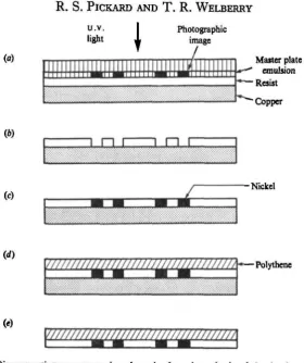
Fig. i. Diagrammatic transverse sections through a four-channel printed circuit microelectrode at successive stages of production, (a) After application of master plate to photoresist coated copper foil. (6) After exposure to u.v. light, removal of master plate and development of photoresist, (c) After electroplating in a nickel salt solution, (d) After attaching polythene to plated surface. («) Finished microelectrode after etching away copper substrate.
M A T E R I A L S A N D M E T H O D S
Construction of the microelectrodes
The technique used is based on that described by Hill & Rigby (1969) for the production of evaporation masks. Diagrams of different types of electrode circuit were prepared with Letra-set dry print on white card. These were photographed on Kodalith Ortho Type 3 film and the images were then reduced optically to the size required for electrode printing. The reduced images were printed on to a 'master' photographic plate (Ilford Formolith G72). The master plate carried several hundred positive images and was used to produce thousands of electrodes.
electro-Journal of Experimental Biology, Vol. 64, No.
Fig. 2
Fig. 2. Printed circuit microelectrodes photographed by transmitted light, (a) Type A electrodes. (6) Type B electrode, i—8 channel numbers, (c) Recording tips of a four-channel type A electrode, (d) Eight-channel type A electrode illustrating printing resolution obtainable.
Printed circuit microelectrodes 41
plated in Watt's nickel plate solution (Fig. 1 c). Because the total area of the electrodes was very small for consistent electroplating, it was necessary to bare about 1000 mm2 of copper to more readily control the depth of nickel deposited. Under these condi-tions a current of o-i A for 15 min was sufficient to complete the plating process. Polythene (0-028 mm in thickness) was fixed to the resist/nickel surface of the copper foil with cyanoacrylate (Fig. 1 d) and the copper was then completely etched away in ammonium persulphate solution leaving the finished nickel electrodes attached to the polythene sheet (Fig. 1 e).
Fine copper wires (0-0508 mm in diameter) were used to connect the microelectrode output terminals to a multi-channel differential preamplifier (Palmer 8122). The copper wires were tinned and threaded individually through fine glass pipettes mounted on micro-manipulators. Each wire was positioned firmly on each output terminal and the joints were secured with an overlay of cyanoacrylate adhesive. The pipettes were then withdrawn and discarded. (Alternative methods of attaching copper wires involved the use of conducting adhesives, spot welding or electroplating the contact joint with copper.) The remaining circuitry was insulated to leave exposed recording tips of approximately 10/ira2. The finished multi-channel circuit was then
cut from the production sheet, complete with its polythene backing. Electrodes were checked microscopically before use and those showing any cross-Unking of channels, caused by excessive nickel plating, were discarded.
Implantation
A worker honeybee was mounted in an experimental holder without using any anaesthetic or damaging restraint (Pickard, 1975). An area of cuticle overlying the protocerebrum was depilated and cut out with a small spade drill (0-07 mm in dia-meter). The hypopharyngeal glands were displaced laterally and a printed circuit microelectrode was positioned either on top of the connective tissue sheath overlying the right corpus pedunculatum or directly beneath the sheath. The electrode was sealed in position and the wound closed with cyanoacrylate adhesive. Recordings were taken from both restrained and free-moving preparations (flying and walking in a plastic box, 178 mm x 114 mm x 38 mm). The electrode outputs were compared with each other or with an indifferent silver wire probe in the haemocoele and displayed on Dynamco 7130 and Telequipment DM64 oscilloscopes, and filmed with Nihon-Kohden PC-2A and Polaroid CR-9 cameras.
RESULTS
R. S. PlCKARD AND T . R. WELBERRY
[image:6.451.73.382.56.394.2]( b ) .. 1 . . . 1 . j . - L i i . i l .
Fig. 3. Recordings from the protocerebrum of a stationary unrestrained worker honeybee, (a) Diagram of the brain (frontal aspect) showing the loci (1-4) over the right corpus pedunculatum (sheath intact) at which records (b) to (/) were obtained, (b-f) Recordings from the same preparation showing synchronous and asynchronous activity in different electrode channels. Traces 1-4 are recordings taken at loci 1-4 through channels 2, 3, 6 and 7, respect-ively, of an eight-channel type B electrode (Fig. 26) compared with an indifferent probe also in the head capsule.
above 100 Hz, were constant features of the recordings. Controls indicated that such low frequency potentials did not represent the detection of muscular activity in the head capsule. Since the exposed area of each electrode tip was sufficient to cover several cells, each transient recorded could reflect the activity of one or several neurones functioning in synchrony.
Printed circuit microelectrodes 43
capacitance coupling where such good conducting pathways as the electrodes are present. It was concluded that recordings of synchronous transients reflected syn-chronized activity at the different electrode tips. Such synchronization may reflect associated activity between Kenyon cells which were situated beneath the printed circuit (Maynard, 1967; Schurmann, 1971).
Chronic preparations were viable for up to five hours. Neural activity was recorded during restricted flight; scenting with Nasanov's gland; walking; orientation to a light source; and cleaning of antennae, wings and metathoracic legs. Consideration of the relationship between recorded activity and behaviour is continuing at the present time.
DISCUSSION
The basic printed circuit microelectrode used in this preliminary study was successful as a surface recording electrode. There are, however, considerable pos-sibilities for its development as a probing multi-channel electrode with projecting conical recording tips at right angles to the existing printed circuit. The printed circuits can be constructed from any of the conventional microelectrode metals such as silver, gold or platinum. With a given printed circuit the impedance characteristics can be controlled through the degree of electrode metal deposition and insulation. By microscopically masking the electrode tips to give the required area of exposure the insulation can be sprayed on to the circuit, preferably in a vacuum.
Since these electrodes are produced photographically from one master plate, it is possible to standardize a particular array of recording points in hundreds of circuits. Furthermore, the original circuit drawing can be accurately modified to change an electrode pattern to suit specific applications as an experimental investigation proceeds. This facility could be extremely useful in a statistical analysis of relative activity levels over a group of cells (Moore et al. 1970). With appropriate modifications it should also be possible to use these printed circuits for other special-ized recording purposes such as monitoring tissue levels of pO2 (Silver, 1965). With the increasing development of microelectronics it may soon be possible to incorporate the first stage preamplification on or very close to the printed microelectrode with considerable reduction in unwanted noise. Such a development would facilitate the current growth of telemetry in biological experimentation (Mackay, 1970).
We are grateful to Miss P. L. Joseph for constructing some of the printed circuits used in this study. Mr E. B. Plumb and colleagues of the Glamorgan Beekeepers Association kindly helped with the establishment of the college hives.
REFERENCES
BURHOWB, M. (1973). The role of delayed excitation in the co-ordination of some metathoracic flight motoneurons of a locust. J. comp. Pkysiol. 83, 135-64.
COLLETT, T. (1971). Connections between wide-field monocular and binocular movement detectors in the brain of a hawkmoth. Z. vergl. Pkysiol. 75, 1-31.
HILL, A. E. &RIOBY,P. A. (1969). Precision manufacture and registration of masks for vacuum evapora-tion, y. Physics E: Scientific Instruments 3, 1084.
HOWSB, P. E. (1975). Brain structure and behaviour in insects. Ann. rev. Entomol. 30, 359-79. HUBER, F. (1965). Neural integration (Central nervous system). In The Physiology of Insecta, vol. II
4 4 R- S. PlCKARD AND T . R. WELBERRY
KAISER, W. & BISHOP, L. G. (1970). Directionally selective motion detecting units in the optic lobe of the honeybee. Z. vergl. Physiol. 67, 403-13.
MACKAY, R. S. (1970). Bio-Medical Telemetry, 2nd edn. New York: John Wiley and Sons Inc. MAYNARD, D. M. (1967). Organisation of central ganglia. In Invertebrate Nervous Systems (ed. C. A. G.
Wiersma), pp. 231-55. Chicago: University Chicago Press.
MOORE, G. P., SEOUNDO, J. P., PERKEL, D. H. & LEVITAN, H. (1970). Statistical signs of synaptic inter-action in neurons. Biopkys. J. 10, 876-900.
PICKARD, R. S. (1975). A simple restraining instrument to facilitate experimental manipulation of the honeybee head. J. apic. Res. 14, 09-100.
ROWELL, C. H. F. (1971). The orthopteran descending movement detector (DMD) neurones: a characterisation and review. Z. vergl. Physiol. 73, 167-94.
SCHORMANN, F. W. (1971). Synaptic contacts of association fibres in the brain of the bee. Brain Res. 36, 160-76.
SILVER, I. A. (1965). Oxygen microelectrodes. Med. electron. Biol. Engng 3, 377-87.
SUZUKI, H. (1975). Convergence of olfactory inputs from both antennae in the brain of the honeybee.
y. exp. Biol. 6a, 11-26.