© 2019, IRJET | Impact Factor value: 7.211 | ISO 9001:2008 Certified Journal | Page 4074
A Brief Introduction to Fuzzy Logic Technique for Fault Diagnosis
J. R. Cahudhari
1, Dr. C. R. Patil
21
Mechanical Engineering Department, SSGB COE&T, Bhusawal, India - 425 201
2
Mechanical Engineering Department, PRMIT&R, Badnera, India - 444 701
---***---Abstract -An Nowadays, fault diagnosis is one of the majorissues in every field of engineering, which may cause failure of the entire system. One of the main causes to occur fault is vibration. Vibration may occur due to mechanical oscillation from industrial machines, railway track nearby human reside, and many more reasons. Due to the interaction between humans and machines, vibration causes serious damage to the human health. Early detection of presence of damage can prevent the catastrophic failure of the structures by appropriately monitoring the response to the system. Hence, it needs to be eradicated faults. In this paper methodology have been introduced to damage detection of a cracked cantilever beam with single crack using analytical, Finite Element Analysis (FEA), fuzzy logic (Triangular, Trapezoidal and Gaussian). The importance and foundation of fuzzy logic is explained. Also steps for creating fuzzy model and analysis of fuzzy mechanism used for crack detection are introduced in detail. Analytical studies has been performed on the cantilever beam with single crack to obtain the vibration characteristics of the beam. Here author intend to introduce fuzzy logic technique for fault diagnosis.
Key Words: Fuzzy Logic, Fault Diagnosis, FIS, Crack
1. INTRODUCTION
Crack is the potential source of failure in the field of engineering. Crack diagnosis in vibrating structure has drawn a lot of attention to mechanical machines and in civil structures and aerospace engineering. In the recent years the era of researchers has motivated towards development of intelligent techniques for crack detection. Many techniques have been employed in the past for damage identification. Some of these are visual (e.g. dye penetrant method) and other NDT uses sensors to detect local faults (e.g. eddy current, magnetic field, radiographs, acoustics and thermal fields).In this chapter fuzzy logic technique has been projected for localization and identification of crack.
Fuzzy logic (FL) is a multi valued logic, which allows interim values to be defined between linguistic expressions like yes/no, high/low, true/false. A form of knowledge representation suitable for notions that cannot be defined precisely, but which depend upon their contexts. Superset of conventional (Boolean) logic that has been extended to handle the concept of partial truth - the truth values between "completely true & completely false".
Fuzzy logic has two different meanings as, in narrow sense: Fuzzy logic is a logical system, which is an extension of multi-valued logic. In a wider sense: Fuzzy logic (FL) is almost synonymous with the theory of fuzzy sets, a theory which relates to classes of objects of unsharp boundaries in which membership is a matter of degree
A K Das et al. [1] have discussed the influence of cracks to the dynamic behavior of a cracked cantilever beam with rectangular cross section. Finite element analysis is being performed on the cracked structure to measure the vibration signature, which is subsequently used in the design of smart system based fuzzy logic in prediction of crack depths and locations following inverse problem approach.
Huh et al. [2] has proposed a new local damage detection method of damaged structures using the vibratory power estimated from accelerations measured on the beam structure. A damage index is newly defined by them based on the proposed local damage detection method and is applied to the identification of structural damage. Numerical simulation and experiment are conducted for a uniform beam to confirm the validity of the proposed method. In the experiments, they have considered the damage as an open crack such as aslit inflicted on the top surface of the beam.
Dayal R Parhi and Sasanka Choudhary [3] presented non destructive method for the detection of crack in terms of crack depth and crack location with the consideration of natural frequency. The crack is analyzed using Fuzzy Logic System and Finite Element Analysis.
Lotfi Zadeh [4] introduced and briefly analyzed the relevant properties of fuzzy sets, the notions of a fuzzy system and a fuzzy class of systems. The work constitutes a very preliminary attempt on introducing into system theory several concepts which provide a way of treating fuzziness in a quantitative manner. The paper closes with a section dealing with optimization under fuzzy constraints in which an approach to problems of this type is briefly sketched.
© 2019, IRJET | Impact Factor value: 7.211 | ISO 9001:2008 Certified Journal | Page 4075
compared the mode shapes for the cracked andundamaged beam to identify the crack parameters.
Deepak K. Agarwalla, Abdul Sadik Khan and Subham Kumar Sahoo [6] uses the GA –Fuzzy controller for the identification of damage in steel cantilever beam in transverse direction subjected to natural vibration.
Dayal R Parhi and Sasanka Choudhary [7] have analyzed the transverse surface crack using fuzzy logic system and finite element analysis. The fuzzy controller uses the hybrid membership functions (combination of triangular, trapezoidal and Gaussian) as input and trapezoidal membership functions as output. By using Several fuzzy rules the results obtained for crack depth and crack location in the Matlab Simulink environment and have been compared with the results obtained from finite element analysis.
Tahaa et al. [8] has introduced a method to improve pattern recognition and damage detection by supplementing intelligent health monitoring with used fuzzy inference system. The Bayesian methodology is used to demarcate the levels of damage to developing the fuzzy system and is examined to provide damage identification using data obtained from finite element analysis for a pre-stressed concrete bridge.
Wada et al. [9] has proposed a fuzzy control method of triangular type membership functions using an image processing unit to control the level of granules inside a hopper. They stated that the image processing unit can be used as a detecting element and with the use of fuzzy reasoning methods good process responses were obtained.
Dayal R Parhi and Sasanka Choudhary [10] describe a comprehensive review of various technical papers in the domain of crack detection in Beam-Like Structure. The various techniques discussed on the basis of dynamic analysis of Crack. The techniques mainly of fuzzy logic neural network, fuzzy system, hybrid neuro genetic algorithm, artificial neural network, artificial intelligence.
Parhi [11] has developed a fuzzy inference based navigational control system for multiple robots working in a clumsy environment. They have been designed to navigate in an environment without hitting any obstacles along with other robots.
Zimmermann [12] has applied fuzzy linear programming approach to solving linear vector maximum problem. The solutions are obtained by fuzzy linear programming. These are found to be efficient solutions then the numerous models suggested solving the vector maximum problem.
2. FUZZY INTERFACE SYSTEM
A fuzzy inference system (FIS) essentially defines a nonlinear mapping of the input data vector into a scalar output, using fuzzy rules. The mapping process involves input/output membership functions, FL operators, fuzzy if–then rules, aggregation of output sets, and defuzzification. An FIS with multiple outputs can be considered as a collection of independent multi input, single-output systems. A general model of a fuzzy inference system (FIS) is shown in Figure 1 The FLS maps crisp inputs into crisp outputs. It can be seen from the figure that the FIS contains four components: the fuzzifier, inference engine, rule base, and defuzzifier. The rule base contains linguistic rules that are provided by experts. It is also possible to extract rules for numeric data. Once the rules have been established, the FIS can be viewed as a system that maps an input vector to an output vector. The fuzzifier maps input numbers into corresponding fuzzy memberships. This is required in order to activate rules that are in terms of linguistic variables. The fuzzifier takes input values and determines the degree to which they belong to each of the fuzzy sets via membership functions. The inference engine defines mapping from input fuzzy sets into output fuzzy sets. It determines the degree to which the antecedent is satisfied with each rule. If the antecedent of a given rule has more than one clause, fuzzy operators are applied to obtain one number that represents the result of the antecedent for that rule. It is possible that one or more rules may fire at the same time. Outputs for all rules are then aggregated. During aggregation, fuzzy sets that represent the output of each rule are combined with a single fuzzy set.
© 2019, IRJET | Impact Factor value: 7.211 | ISO 9001:2008 Certified Journal | Page 4076
Figure 1 Block diagram of Fuzzy Interface SystemFigure 2 Schematic diagram of a Fuzzy Interface System
2.1 Importance of Fuzzy Logic:
Here is a list of general observations about fuzzy logic:
Fuzzy logic is conceptually easy to understand: The mathematical concepts behind fuzzy reasoning are very simple. What makes fuzzy nice is the "naturalness" of its approach and not its far-reaching complexity. Fuzzy logic is flexible: With any given system, it's easy
to massage it or layer more functionality on top of it without starting again from scratch.
Fuzzy logic is tolerant of imprecise data: Everything is imprecise if you look closely enough, but more than that, most things are imprecise even on careful inspection. Fuzzy reasoning builds this understanding into the process rather than tacking it onto the end. Fuzzy logic can model nonlinear functions of
arbitrary complexity: You can create a fuzzy system to match any set of input-output data. This process is made particularly easy by adaptive techniques like Adaptive Neuro-Fuzzy Inference Systems (ANFIS), which are available in the Fuzzy Logic Toolbox.
Fuzzy logic can be built on top of the experience of experts: In direct contrast to neural networks, which take training data and generate opaque, impenetrable models, fuzzy logic lets you rely on the experience of people who already understand your system.
Fuzzy logic can be blended with conventional control techniques: Fuzzy systems don't necessarily replace conventional control methods. In many cases fuzzy systems augment them and simplify their implementation.
Fuzzy logic is based on natural language: The basis of fuzzy logic is the basis of human communication.
This observation underpins many of the other statements of fuzzy logic.
2.2 Foundations of Fuzzy Logic
1) Fuzzy Set
2) Membership Function
3) Logical Operations
4) If-Then Rules
1) Fuzzy Set: Fuzzy logic starts with the concept of a fuzzy set. A fuzzy set is a set without a crisp, clearly defined boundary. It can contain elements with only a partial degree of membership. To understand what a fuzzy set is, first consider what is meant by what we might call a classical set. A classical set is a container that wholly includes or wholly excludes any given element. For example, consider the set of days comprising a weekend. The Figure 3 is one attempt on classifying the weekend days.
[image:3.595.348.521.468.533.2]Most would agree that Saturday and Sunday belong, but what about Friday? It feels like a part of the weekend, but somehow it seems like it should be technically excluded. So in the Figure 3 above Friday tries its best to sit on the fence. Classical or normal sets wouldn't tolerate this kind of thing. Either you're in or you're out. Human experience suggests something different, though: fence sitting is a part of life.
Figure 3 Days of the Weekend
“In fuzzy logic, the truth of any statement becomes a matter of degree.”
[image:3.595.312.553.666.737.2]The Figure 4, left is a plot that shows the truth values for weekend-ness if we are forced to respond with an absolute yes or no response. On the right is a plot that shows the truth value for weekend-ness if we are allowed to respond with fuzzy in-between values.
© 2019, IRJET | Impact Factor value: 7.211 | ISO 9001:2008 Certified Journal | Page 4077
2) Membership Function: The membership function is agraphical representation of the magnitude of participation in each input. Membership Function (MF) is a curve that defines how each point in the input space is mapped to a membership value of 0 and 1.
The input space is sometimes referred to as the universe of discourse, a fancy name for a simple concept. A classical set might be expressed as
A = {x | x > 6}
A fuzzy set is an extension of a classical set. If X is the universe of discourse and its elements are denoted by x, then a fuzzy set A in X is defined as a set of ordered pairs.
A = {x, μA(x) | x ∈ X}
[image:4.595.307.561.58.226.2]μA(x) is called the membership function (or MF) of x in A. The membership functions maps each element of X to a membership value of 0 and 1. The Fuzzy Logic Toolbox includes eleven built-in membership function types. These eleven functions are, in turn, built from several basic functions: piecewise linear functions, the Gaussian distribution function, the sigmoid curve, and quadratic and cubic polynomial curves. Figure 5 shows the membership function, variable and linguistic term.
Figure 5 Membership Function, Variable and Linguistic Term.
[image:4.595.78.249.416.539.2]3) Logical Operations: The most important thing to realize about fuzzy logical reasoning is the fact that it is a superset of standard Boolean logic. In other words, if we keep the fuzzy values of their extremes of 1 (completely true), and 0 (completely false), standard logical operations will hold. Fuzzy Logic Operators are used to write logic combinations of fuzzy notions (i.e. to perform computations on degree of membership). Figure 6 shows operators between Fuzzy Sets.
Figure 6 Operators between Fuzzy Sets
According to Lotfi Zadeh [4] operators
1) Intersection: The logic operator corresponding to the intersection of sets is AND.
µ(A AND B) = MIN(µ(A), µ(B))
2) Union: The logic operator corresponding to the union of sets is OR.
µ(A OR B) = MAX(µ(A), µ(B))
3) Negation: The logic operator corresponding to the complement of a set is the negation.
µ(NOT A) = 1 - µ(A)
4) If-Then Rules: Fuzzy sets and fuzzy operators are the subjects and verbs of fuzzy logic. These if-then rule statements are used to formulate the conditional statements that comprise fuzzy logic. A single fuzzy if-then rule assumes the form if x is A then y is B where A and B are linguistic values defined by fuzzy sets on the ranges (universes of discourse) X and Y, respectively. If part of the rule "x is A" is called the antecedent or premise, while the then-part of the rule "y is B" is called the consequent or conclusion.
2.3 STEPS FOR CREATING FUZZY MODEL
Step 1: Fuzzy Inputs (Fuzzification)
© 2019, IRJET | Impact Factor value: 7.211 | ISO 9001:2008 Certified Journal | Page 4078
Figure 7 FuzzificationStep 2: Apply Fuzzy Operators
[image:5.595.299.554.52.318.2]Once the inputs have been fuzzified, we know the degree to which each part of the antecedent has been satisfied for each rule. If a given rule has more than one part, the fuzzy logical operators are applied to evaluate the composite firing strength of the rule (see Figure 8)
Figure 8 Activation of Fuzzy Operators
Step 3: Apply the Implication Method
The implication method is defined as the shaping of the output membership functions of the basis of the firing strength of the rule. The input for the implication process is a single number given by the antecedent, and the output is a fuzzy set. Two commonly used methods of implication are the minimum and the product (see Figure 9)
Figure 9 Implication
Step 4: Aggregate all Outputs
[image:5.595.40.282.322.401.2]Aggregation is a process whereby the outputs of each rule are unified. Aggregation occurs only once for each output variable. The input to the aggregation process is the truncated output fuzzy sets returned by implication process of each rule. The output of the aggregation process is the combined output fuzzy set (see Figure 10)
Figure 10 Aggregations of Rules
Step 5: Defuzzify
The input for the defuzzification process is a fuzzy set (the aggregated output fuzzy set),and the output of the defuzzification process is a crisp value obtained by using some defuzzification method such as the centroid, height, or maximum.
At the end of inferences, the output fuzzy set is determined, but cannot be directly used to provide the operator with precise information or control an actuator. We need to move from the “fuzzy world” to the “real world”: this is known as defuzzification. A number of methods can be used, the most common of which are calculation of the “centre of gravity” of the fuzzy set (see Figure 11 ).
Free” and “able” rules Fuzzy rules bases, in their general case, use membership functions of system variables, and rules that can be written textually. Each rule uses its own inputs and outputs, as shown by the example below:
R1: IF “high temperature” THEN “high output”
R2: IF “average temperature” AND “low pressure” THEN “average output”
R3: IF “average temperature” AND “high pressure” THEN “low output”
[image:5.595.46.279.539.618.2]© 2019, IRJET | Impact Factor value: 7.211 | ISO 9001:2008 Certified Journal | Page 4079
Figure 11 Defuzzification by Centre of Gravity3 ANALYSIS OF FUZZY MECHANISM USED FOR CRACK DETECTION
The fuzzy controller has been developed (as shown in Figure 12) where there are 3 inputs and 2 outputs parameter.
Figure 12 Schematic diagram of Fuzzy Inference System
The linguistic term used for the inputs are as follows;
• Relative first natural frequency = “FNF”;
• Relative second natural frequency = “SNF”,
• Relative third natural frequency = “TNF”
The linguistic term used for the inputs are as follows;
Relative crack depth = “RCD”,
Relative crack location = “RCL”
The fuzzy models developed in the current analysis, based on triangular, Gaussian and trapezoidal membership functions have got three or six input parameters and two or four output parameters. The pictorial view of the triangular membership, Gaussian membership, trapezoidal membership fuzzy models are shown in Figure 13(a), Figure 13(b) and Figure 13(c) respectively.
Figure 13 (a) Triangular Fuzzy Model
Figure 13 (b) Guassian Fuzzy Model
Figure 13(c) Trapezoidal Fuzzy Model
Based on the above fuzzy subset the fuzzy rules are defined in a general form as follows: If (FNF is FNFi and SNF is SNFj and TNF is TNFk) then (CD is CDijk
and CL is CLijk) Where i= 1to 9, j=1 to 9, k=1 to 9 (1)
Because of “FNF”, “SNF”, “TNF” have 9 membership functions each.
From the above expression (4.4), two set of rules can be written
If (FNF is FNFi and SNF is SNFj and TNF is TNFk) then
CD is CDijk (2 a)
If (FNF is FNFi and SNF is SNFj and TNF is TNFk) then
CL is CLijk (2 b)
According to the usual Fuzzy logic control method (Das and Parhi [1]), a factor Wijk is defined for the rules as follows:
Wijk=μfnfi (freqi) Λ μsnfj (freqj) Λ μtnfi (freqk)
Where freqi, freqj and freqk are the first, second and third natural frequency of the cantilever beam with crack respectively ; by Appling composition rule of interference (Das and Parhi [1,13]) the membership values of the relative crack location and relative crack depth (location)CL.
μrclijk (location) = Wijk Λ μrclijk (location) length CL
[image:6.595.30.275.285.366.2] [image:6.595.62.266.639.713.2]© 2019, IRJET | Impact Factor value: 7.211 | ISO 9001:2008 Certified Journal | Page 4080
μrclijk (depth) = Wijk Λ μrclijk (depth) depth CDThe overall conclusion by combining the output of all the fuzzy can be written as follows:
μrclijk (location) = μrcl111 (location) V.….V μrclijk (location)
V.V μrcl9 9 9 (location) (3a)
μrclijk (location) = μrcl111 (depth) V.…..V μrclijk (depth)
V….V μrcl9 9 9 (depth) (b)
The crisp values of relative crack location and relative crack depth are computed using the centre of gravity method (Das and Parhi [1, 13]) as:
4 Function of Fuzzy Controller for Localization and Identification of Crack
The inputs to the fuzzy controller are relative first natural frequency; relative second natural frequency; relative third natural frequency. The outputs from the fuzzy controller are relative crack depth and relative crack location. Several hundred fuzzy rules are outlined to train the fuzzy controller. Twenty four numbers of the fuzzy rules out of several hundred fuzzy rules are being listed in Table: 2. the output data has been generated from the input data and the rule base.
5. RESULTS AND DISCUSSION
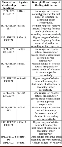
The fuzzy controller has been designed using three types of membership functions, i.e. Triangular, Trapezoidal and Gaussian membership function. The linguistic terms used for the fuzzy membership function have been specified in Table:1. The fuzzy rules being used for the fuzzy inference system are specified in the Table: 2. Out of several hundreds of fuzzy rules only twenty four fuzzy rules has been indicated in the table. Figure 14 to Figure 16 shows the operation of fuzzy inference system to exhibits the fuzzy results after defuzzification when rule 2 and 15 of the Table:2 are activated for triangular, trapezoidal, Gaussian and hybrid membership functions respectively. The comparison of the
[image:7.595.308.559.183.778.2]results obtained from theoretical and the fuzzy controller of triangular membership function, fuzzy controller with trapezoidal membership function, fuzzy controller with Gaussian membership function are presented in Table:3.
Table: 1 Linguistic Terms used for Fuzzy Membership Functions
Name of the Membership functions
Linguistic
terms Description and range of the linguistic terms
L1F1,L1F2,
L1F3,L1F4 fnf1to4 natural frequency for first Low ranges of relative mode of vibration in
ascending order respectively. M1F1,M1F2,M
1F3 fnf5to7 Medium ranges of relative natural frequency for first mode of vibration in ascending order respectively. H1F1,H1F2,H1
F3,H1F4 fnf8to11 natural frequency for first Higher ranges of relative mode of vibration in ascending order respectively L2F1,L2F2,
L2F3,L2F4 snf1to4 Low ranges of relative natural frequency for second mode of vibration in
ascending order respectively. M2F1,M2F2,M
2F3 snf5to7 Medium ranges of relative natural frequency for second mode of vibration
in ascending order respectively. H2F1,H2F2,H2
F3,H2F4 snf8to11 Higher ranges of relative natural frequency for first mode of vibration in
ascending order respectively L3F1,L3F2,
L3F3,L3F4 tnf1to4 Low ranges of relative natural frequency for second mode of vibration in
ascending order respectively. M3F1,M3F2,M
3F3 tnf5to7 Medium ranges of relative natural frequency for second mode of vibration in ascending
order respectively. H3F1,H3F2,H3
F3,H3F4 tnf8to11 Higher ranges of relative natural frequency for first mode of vibration in
ascending order respectively. SD1,SD2,SD3,S
© 2019, IRJET | Impact Factor value: 7.211 | ISO 9001:2008 Certified Journal | Page 4081
MD3 crack depth in ascending
order respectively. LD1,LD2,
LD3,LD4 rcd8to11 Larger crack depth in ascending ranges of relative order respectively. SL1,SL2,SL3,SL
4 rcl1to4 crack location in ascending Small ranges of relative order respectively. ML1,ML2,
ML3 rcl5to7 crack location in ascending Medium ranges of relative order respectively. BL1,BL2,
BL3,BL4 rcl8to11 crack location in ascending Bigger ranges of relative order.
Table: 2 Fuzzy Rules for Fuzzy Inference System
SR. No Some Examples of Fuzzy rule used in the Fuzzy Controller
1 If fnf is L1F1, snf is L2F1, tnf is L3F1 then rcd is SD1 and rcl is SL1
2 If fnf is L1F1, snf is L2F2, tnf is L3F2 then rcd is SD2 and rcl is SL2
3 If fnf is L1F1, snf is L2F2, tnf is L3F3 then rcd is SD1 and rcl is SL2
4 If fnf is M1F1, snf is M2F1, tnf is M3F1 then rcd is MD1 and rcl is ML1
5 If fnf is M1F1, snf is M2F2, tnf is M3F2 then rcd is MD2 and rcl is ML2
6 If fnf is M1F1, snf is M2F2, tnf is M3F3 then rcd is MD1 and rcl is ML2
7 If fnf is M1F2, snf is M2F1, tnf is M3F1 then rcd is MD2 and rcl is ML1
8 If fnf is M1F2, snf is M2F2, tnf is M3F2 then rcd is MD2 and rcl is ML3
9 If fnf is M1F3, snf is M2F1, tnf is M3F2 then rcd is MD3 and rcl is ML1
10 If fnf is M1F2, snf is M2F3, tnf is M3F2 then rcd is MD1 and rcl is ML3
11 If fnf is L1F2, snf is L2F1, tnf is L3F1 then rcd is SD2 and rcl is SL1
12 If fnf is L1F2, snf is L2F3, tnf is L3F3 then rcd is SD2 and rcl is SL3
13 If fnf is L1F3, snf is L2F1, tnf is L3F2 then rcd is SD3 and rcl is SL1
14 If fnf is L1F2, snf is L2F3, tnf is L3F2 then rcd is SD1 and rcl is SL3
15 If fnf is L1F3, snf is L2F3, tnf is L3F3 then rcd is SD3 and rcl is SL3
16 If fnf is M1F3, snf is M2F3, tnf is M3F3 then rcd is MD3 and rcl is ML3
17 If fnf is H1F1, snf is H2F1, tnf is H3F1 then rcd is LD1 and rcl is BL1
18 If fnf is H1F1, snf is H2F2, tnf is H3F2 then rcd is LD2 and rcl is BL2
19 If fnf is H1F1, snf is H2F3, tnf is H3F3 then rcd is LD1 and rcl is BL2
20 If fnf is H1F2, snf is H2F1, tnf is H3F1 then rcd is LD2 and rcl is BL1
21 If fnf is H1F2, snf is H2F2, tnf is H3F2 then rcd is LD2 and rcl is BL3
22 If fnf is H1F3, snf is H2F1, tnf is H3F2 then rcd is LD3 and rcl is BL1
23 If fnf is H1F2, snf is H2F3, tnf is H3F2 then rcd is LD1 and rcl is BL3
24 If fnf is H1F3, snf is H2F3, tnf is H3F3 then rcd is LD3 and rcl is BL3
Table: 3 Comparison of Results between Theoretical Analysis and different Fuzzy Controller Analysis
First Natural Frequency fnf Second Natural Frequency snf Third Natural Frequency tnf
Theoretical Triangular Fuzzy Controller Trapezoidal Fuzzy Controller Gaussian Fuzzy Controller Relative crack depth rcd Relative crack location rcl
rcd rcl rcd rcl rcd rcl
© 2019, IRJET | Impact Factor value: 7.211 | ISO 9001:2008 Certified Journal | Page 4082
Inputs for trapezoidal membership function
Rule No. 2 of Table: 2 is activated Rule No. 15 of Table: 2 is activated
Outputs Obtained From Triangular Membership Function
Relative Crack Depth
Relative Crack Location
© 2019, IRJET | Impact Factor value: 7.211 | ISO 9001:2008 Certified Journal | Page 4083
Inputs for trapezoidal membership function
Rule No. 2 of Table: 2 is activated Rule No.15 of Table: 2 is activated
Outputs Obtained From Trapezoidal Membership Function
Relative Crack Depth
Relative Crack Location
© 2019, IRJET | Impact Factor value: 7.211 | ISO 9001:2008 Certified Journal | Page 4084
Inputs for Gaussian membership function
Rule No. 2 of Table: 2 is activated Rule No.15 of Table: 2 is activated
Outputs Obtained From Gaussian Membership Function
Relative Crack Depth
Relative Crack Location
Figure: 16 Resultant values of relative crack depth and relative crack location of Gaussian membership function when Rules 2 and 15 of Table:2 are activated.
6. CONCLUSION
The fuzzy controller has been designed using Triangular, Trapezoidal and Gaussian membership function. A fuzzy controller uses three natural frequencies as inputs where as the crack depth and crack location as output. It has been observed that the natural frequencies of the
© 2019, IRJET | Impact Factor value: 7.211 | ISO 9001:2008 Certified Journal | Page 4085
7. REFERENCES
[1] Amiya Kumar Dash, Dayal.R.Parhi, “Development of An Inverse Methodology for Crack Diagnosis using AI Technique”, International Journal of Computational Materials Science and Surface Engineering (IJCMSSE) 4(2), 2011, 143-167.
[2] Y. C. Huh, T.Y. Chung, S. J. Moon, H. G. Kil, J. K. Kim, “Damage Detection in Beams Using Vibratory Power Estimated from the Measured Accelerations”, Journal of Sound and Vibration ,330(15), pp.3645-3665,2011.
[3] Dayal R Parhi and Sasanka Choudhury, “Intelligent Fault Detection of a Cracked Cantilever Beam Using Fuzzy Logic Technology with Hybrid Membership functions”, International Journal of Artificial Intelligence and Computational Research, 2011, pp.9-16
[4] Lotfi Zadeh, “Fuzzy Sets and Systems”, Int. J. General Systems, Vol. 17, pp. 129-138
[5] A. Salam, Y. Alsabbagh, O.M. Abuzeid , Mohammad H. Dado, “Simplified Stress Correction Factor to Study the Dynamic Behavior of A Cracked Beam”, Applied Mathematical Modeling, 33, pp. 127–139, 2009.
[6] Deepak K. Agarwalla, Abdul Sadik Khan and Subham Kumar Sahoo “Application of Genetic Fuzzy System for Damage Identification in Cantilever Beam Structure”, 12th International Conference on Vibration Problems, ICOVP 2015, Procedia Engineering 144 (2016)
[7] Dayal R Parhi and Sasanka Choudhury, “Smart Crack Detection of A Cracked Cantilever Beam using Fuzzy Logic Technology with Hybrid Membership Functions”, Journal of Engineering and Technology Research Vol. 3(8), pp. 270-278, August 2011 [8] M.M. R. Tahaa and J. Lucero, “Damage identification
for structural health monitoring using fuzzy pattern recognition”, Engineering Structures, 27, pp.1774– 1783, 2005.
[9] K. Wada, N. Hayano, and H. Oka, “Application of the Fuzzy Control Method for Level Control of A Hopper”, Advanced Powder Technology, 2, pp.163– 172,1991.
[10] D. R. K. Parhi and Dash Amiya Kumar, “Analysis of Methodologies Applied for Diagnosis of Fault in Vibrating Structures”, Int. J. Vehicle Noise and Vibration, Vol. 5, No. 4, 271-286, 2009.
[11] D. R. Parhi, “Navigation of Mobile Robot using a Fuzzy Logic Model”, Journal of Intelligent and Robotic Systems: Theory and Applications, 42, pp. 253-273, 2005.
[12] H.J. Zimmermann, “Fuzzy programming and linear programming with several objective functions”, Fuzzy Sets and Systems, 1, pp.45–55, 1978.
[13] Harish Ch. Das and Dayal R. Parhi, “Online Fuzzy Logic Crack Detection of A Cantilever Beam”,