Technical Reference Manual
~
BU~lOGIC
S[SI HOST ADAPTERS fOR
Revision History
Revision Change Activity Date
A Release 6/1/94
Compliance Statements
This device complies with Part 15 of the FCC Rules. Operation is subject to the following two conditions:
(1) this device may not cause harmful interference, and (2) this device must accept any interference re-ceived, including interference that may cause undesired operations.
Declaration of the Manufacturer/Importer
We hereby certify that the SCSI Host Adapter for PCI, VESA, EISA and ISA, in compliance with the re-quirements of BMPT Vfg 243/1991, is RFI suppressed. The normal operation of some equipment (e.g., . signal generators) may be subject to specific restrictions. Please observe the notices in the user's manual.
The marketing and sale of the equipment was reported to the Federal Office for Telecommunication Per-mits (BZT). The right to retest this equipment to verify compliance with the regulation was given to the ZZF.
Bescheinungung des Herstellers/lmporteurs
Hiermit wird bescheinigt, das SCSI Host Adapter for PCI, VESA, EISA and ISA in Uebereinstimmung mit den Bestimmungen der BMPT-AmtsbIVfg 243/1991 funk-entstort ist. Der vorschriftsmassige Be-treib mancher Gerate (z. B. Messender) kann allerdings gewissen Einschrankungen unterliegen. Beacht-en Sie deshalb die Hinweise in der BediBeacht-enungsanleitung.
Dem Bundesamt fUr Zulassungen in der Telekommunikation wurde das Inverkehrbringen dieses Gerates angezeigt und die Berechtigung zur Ueberpriifung der Serie auf die Einhaltung der Bestimmu-ngen eingeraumt.
EN 55 022 Declaration of Conformance
This is to certify that BusLogic SCSI Host Adapters are shielded against the generation of radio interfer-ence in accordance with the application of Council Directive 89/336/EEC, Article 4a. Conformity is de-clared by the application of EN 55 022:1987 Class B (CISPR 22:1985/BS 6527:1988).
Copyright
© Copyright 1994 BusLogic Inc. All rights reserved.
BusLogic Inc makes no warranty
of
any kind with regard to this material, including, but not limited to, the implied warranties of merchantability and fitness for a particular purpose. BusLogic is not liable for any errors contained herein or incidental or consequential damages in connection with furnishing, per-formance or use of this material.This document contains proprietary information which is protected by copyright. All rights are re-served. No part of this document may be photocopied, reproduced or translated to another language without prior written consent of BusLogic Inc.
Trademarks
Table of Contents
Preface
Part 1
Adapter Operation
Part 2
pcr
Host AdaptersPart 3
VESA Host Adapters
Part 4
EISA Host Adapters
Part 5
ISA Host Adapters
Preface
Contents
The BusLogic SCSI Host Adapter Technical Reference Manual is intended for sys-tem software programmers desiring to develop deviee driver software for BusLog-ie's family of SCSI adapter products.
This manual covers adapter architecture, hardware and software operation and in-cludes electrical signaling information for each bus architecture.
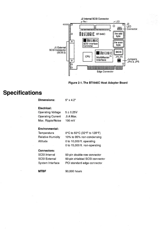
Products covered in this document include:
• BT-946C PCI Fast SCSI Host Adapter (10 MBytes/ sec synchronous data transfer rate; no floppy connector)
• BT-440/445C VESAFast SCSI Host Adapter (10 MBytes/ sec synchronous data transfer rate; BT-44OC has no floppy connector)
• BT-746/747C EISA Fast SCSI Host Adapter (10 MBytes/ sec synchronous data transfer rate; BT-746C has no floppy connector)
• BT-545C PC/AT Fast SCSI Host Adapter (10 MBytes/ sec synchronous data transfer rate)
• BT-540CF PC/AT Fast SCSI Host Adapter (with Centronics external SCSI con-nector)
This manual is organized in the following manner:
Part 1: Adapter Operation
• Section 1 contains an overview to BusLogie's MultiMaster™ technology. • Section 2 details adapter hardware components and operation.
• Section 3 discusses software operation between the host adapter and the host system.
• Section 4 describes the adapter's SCSI electrical interface. • Section 5 describes the adapter's floppy controller interface. • Section 6 details adapter internal diagnostics.
• Appendix A is a list of industry acronyms.
Part 2: PCI Host Adapters
• Section 1 includes descriptions and specifications for the BT-946C host adapter. • Section 2 describes the electrical interface for the BT-946C host adapter.
• Section 3 contains the PCI bus timing diagrams.
Part 3: VESA Host Adapters
• Section 1 includes descriptions and specifications for the BT -440 /44SC host adapter.
• Section 2 describes the electrical interface for the BT -440/ 44SC host adapter. • Section 3 contains the VL-Bus timing descriptions.
Part 4: EISA Host Adapters
• Section 1 includes descriptions and specifications for the BT-746/747C host adapter.
• Section 2 describes the electrical interface for EISA host adapters. • Section 3 contains the EISA bus master timing diagrams.
Part 5: ISA Host Adapters
• Section 1 includes descriptions and specifications for the S4OCF and the BT-54SC host adapters.
• Section 2 describes the electrical interface for ISA host adapters. • Section 3 contains the ISA bus master timing diagrams.
Related Documentation
Refer to the user's guide provided with your BusLogic host adapter for details on host adapter installation and configuration.
Notational Conventions
The following conventions are used throughout this manual:
Convention Description
UPPERCASE Used to indicate the names of keys. A hyphen indicates an active low signal.
+ A plus sign indicates an active high signal.
1
OU~lOGIC
PART
1
Part 1 : Contents
Section 1-1: BusLogic MultiMastering Technology
Introduction ... : ... 1-1 Bus Mastering DMA ... 1-1 Description ... 1-2 Configuration ... 1-2 Bus Master Transfers ... 1-3 MultiMaster Advantages ... 1-4
Section 1-2: Hardware Description
Adapter Architecture ... 1-7 Bus Master DMA Controller ... 1-8 Advanced SCSI Controller ... 1-8 Microprocessor Unit (MPU) ... 1-9 Local BIOS ROM ... 1-9 Floppy Disk Controller ... 1-9 Host DMA Data Transfer Control. ... 1-9 ISA ... 1-9 EISA ... 1-9 VESA ... 1-10 PCI ... 1-10 Hardware Registers ... 1-10 Control Register (Write Only) I/O Base Address + 0 ... 1-11 Status Register (Read Only) I/O Base Address + 0 ... 1-12 Command/Parameter Register (Write Only) I/O Base Address + 1 ... 1-13 Data In Register (Read Only) I/O Base Address + 1.. ... 1-14 Interrupt Register (Read Only) I/O Base Address + 2 ... 1-15 Reset Operations ... 1-17 Host-Initiated Reset Operations ... 1-17 SCSI Bus Reset Operations ... 1-18
Section 1-3: Software Interface
Contents, continued
32- Bit Mode Command Queueing ... 1-46 Implementation Requirements ... 1-47 Project Relationship ... 1-47 BIOS Command Interface ... 1-47 BIOS Commands and Input Parameters ... 1-48 BIOS Command Completion Status ... 1-50 BIOS Disk Commands ... 1-51
Section 1-4: SCSI Electrical Interface
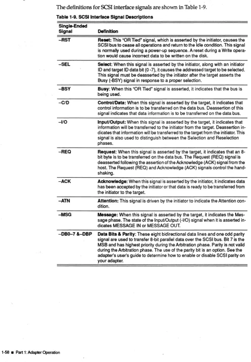
. SCSI Signal Interface ... 1-57 SCSI Signal Definitions ... 1-58
Section 1-5: Floppy Drive Pin Assignments Section 1-6: Internal Diagnostics
Section 1-A: List of Acronyms
List of Figures
Section 1-1: BusLogic MultiMastering Technology
l-l.Typical MultiMaster SCSI Adapter ... 1-2
Section 1-2: Hardware Description
1-2. System Architecture ... 1-7 1-3. Host Adapter Architecture ... 1-8 1-4. Control Register (Write) ... 1-11 1-5. Status Register (Read) ... 1-12 1-6. Command/Parameter Register (Write) ... 1-13 1-7. Data In Register (Read) ... 1-14 1-8. Interrupt Register (Read Only) ... 1-15
Section 1-3: Software Interface
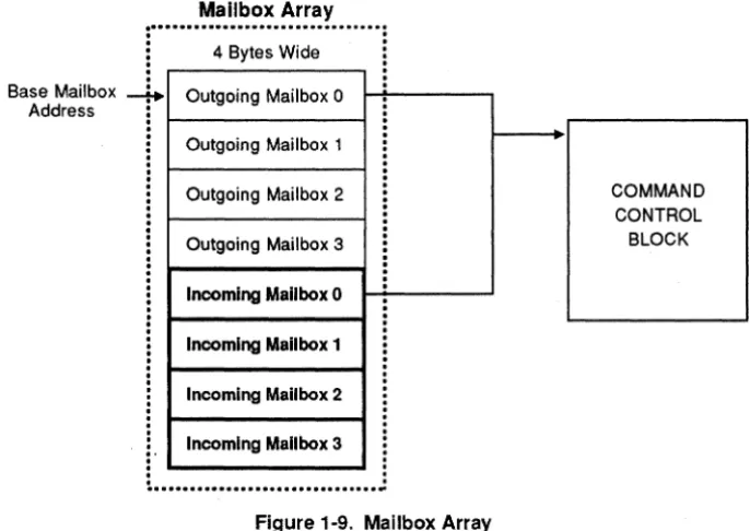
1-9. Mailbox Array ... 1-33 1-10. Scatter-Gather Data Segment List-CCB Bytes 7-9 ... 1-45 1-11. Scatter-Gather Data Segment List-CCB Bytes 8-11 ... 1-45
Section 1-4: SCSI Electrical Interface
List of Tables
Section 1-2: Hardware Description
1-1. Host Adapter Hardware Registers ... , ... 1-10
Section 1-3: Software Interface
1-2. Host Adapter Commands ... 1-23 1-3. Command Control Block Format ... : ... 1-36 1-4. Command Control Block Field Definitions ... 1-37 1-5. Command Control Block Field Definitions ... 1-43 1-6. Valid Host Adapter BIOS Disk Functions ... 1-48 1-7. Valid BIOS Disk Functions ... 1-51
Section 1-4: SCSI Electrical Interface
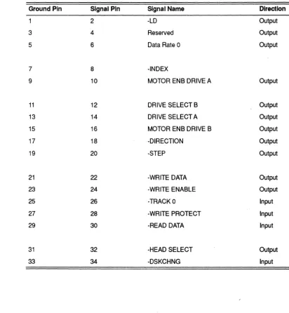
1-8. Single-Ended SCSI Interface Signal Pin Assignments ... 1-57 1-9. SCSI Interface Signal Descriptions ... 1-58
Section 1-5: Floppy Drive Pin ASSignments
1-10. Floppy Disk Controller Pin Assignments ... 1-59
11 _ _ _ _ _
_
BusLogic MultiMastering Technology
Introduction
Bus mastering data transfers are commonly used by intelligent I/O controllers to increase system performance by off-loading the low level control tasks to a dedi-cated micro-controller. BusLogic has created a unique technology for implement-ing a diverse family of high performance bus masterimplement-ing SCSI host adapters while maintaining a high degree of compatibility among them. This technology is called MultiMaster™ and is implemented in a single ASIC. The MultiMaster technology is utilized on all B~Logic bus mastering adapters allowing them to share common device drivers, firmware and BIOS. The following describes the key features, capa-bilities and benefits of BusLogic MultiMaster technology.
Bus Mastering DMA
Bus mastering DMA is a form of information transfer between two devices. The advantages of bus mastering in a PC environment are that it requires less host CPU time and offers high performance data transfers. An intelligent bus master device will use a micro-controller or micro-processor to perform complex I/O operations that would otherwise require interaction from the host system CPU. BusLogic telligent SCSI controllers utilize a 16-bit micro-controller to off-load control of in-formation transfers, thus freeing the system CPU for other tasks and increasing overall system performance as well as I/O performance.
Description
Configuration
BusLogic SCSI Adapter for All Supported Buses
Local RAM/ROM
BIOS
MicroControlier and Support
Micro-Controller Bus
MultiMaster
SCSI BUS
SCSI Controller
High Speed DMA Bus
1 _ _ _ _ _ _ _ _ _ _ _ _ _ _ _ _ _ _ _ _ _ _ _ _ _ _ _ _ _ _ _ _ _ _ _ _ _ _ _ _ _ _ _ _ _ _ _ _ _ _ _ _ _ _ _ _ _ _ _ _ _ _ _ _ _ _ _ _ _ _ _ ~
Host BUS
[image:14.613.65.541.61.450.2]ISA, EISA, MCA, VL-Bus, PCI
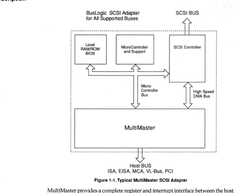
Figure 1-1. Typical MultiMaster SCSI Adapter
MultiMaster provides a complete register and interrupt interface between the host system and the host adapter microcontroller. SCSI command overhead is reduced by reading and updating mailboxes in host memory without intervention by the host adapter microcontroller. Data transfers between the SCSI controller and host system memory are under complete control of the MultiMaster ASIC, from system bus arbitration to the completion of data transfer.
The MultiMaster ASIC is configured to interface with a particular system bus by
hard wiring three mode select pins. Each host adapter has these pins tied to logic levels representing the host bus the adapter interfaces with. The ASIC contains the
bus interface protocols required for each supported system bus. By embedding all the bus specific protocols in the MultiMaster ASIC the microcontroller and
firm-ware design issues become independent of the target host platform.
Registers within the MultiMaster ASIC are configured at power-up to determine host adapter operating parameters.
In an MCA system the MultiMaster ASIC monitors the CDSETUP and address sig-nals to allow the configuration registers to be read and written by the host system. CDSETUP is unique for each slot on the MCA bus allowing MCAadapter cards to use the same set of
1/
a
addresses for configuration registers and avoid bus conten-tion problems. During power-on initializaconten-tion the host system BIOS reads anadapter ID from the MultiMaster configuration registers. The 10 field is used to look up a set of operating parameters previously stored in the system CMOS mem-ory. If no match is found for the ID field the system will invoke a configuration pro-gram allowing the operating parameters for this adapter card to be defined and stored for future power on initializations.
EISA compatible adapter cards use I/ 0 addresses OzC80h - OzC84h for configura-tion purposes. The EISA motherboard generates I/O cycles to these addresses on a per slot basis by only activating the AENz (z represents slot number) signal for the desired slot. This allows each EISA compatible add-in card to decode the same register address range for configuration purposes. Software running on the system sees each card's I/O register at unique addresses.
PCI is very different from MCA or EISA during power-on initialization. The PC! system BIOS will scan the system bus and assign I/O port address, BIOS memory address and interrupt level dynamically each time the system is powered up. This fully automatic initialization is also supported by the BusLogic MultiMaster ASIC.
In an environment such as the ISA and VL-Bus, boot time configuration is not per-formed by the host system. In these environments the host adapter microcontroller will configure the MultiMaster based on information read from switches or stored in EEPROM (BusLogic Model C boards only).
The MultiMaster ASIC maintains a high level of isolation between the host envi-ronment and adapter firmware, allowing a common architecture to be applied to all BusLogic bus mastering SCSI host adapters.
Bus Master Transfers
There are three basic phases of a bus master transfer: arbitration, where the bus master requests and gains access to the system bus; data transfer, in which the bus master has control of the bus and is actively transferring data across the bus. Data transfer is followed by bus release once all available data has been transferred or bus release is being forced to allow another device access or a system memory re-fresh cycle. Although signals and timing vary from one bus type to another, our MultiMaster technology fully automates the data transfer process.
Arbitration
Once a DMA transfer has been programmed into the MultiMaster by the local
mi-croprocessor, the resulting bus master transfer is completely automated by the MultiMaster ASIC. Bus arbitration is initiated by asserting the DMA request or bus request signal appropriate to the particular environment the MultiMaster is resid-ing in. The host system then responds with an acknowledge signal grantresid-ing access to the system bus. The MultiMaster then asserts a host bus signal to indicate it will be acting as a bus master. The host adapter is now the active bus master and has complete control over the system bus. In an ISA system the MultiMaster arbitrates for the system bus by asserting the DMA request line and waiting for a DMA ac-knowledge.
Data Transfer
happens: (1) the data transfer is complete, (2) the host adapter is unable to continue transferring due to an empty or full FIFO buffer or (3) the host system requires the bus to be released.
Bus Release
During the bus release phase the MultiMaster will relinquish control of the system bus through the appropriate protocol for the currently supported host bus. For ex-ample in an ISA system the MASTER signal is released and the address and data lines are tri-stated. DMA request is then released and the host system de-asserts the DMA acknowledge signal.
Preempt
The MultiMaster will release the host system bus when preempted. Most ad-vanced system bus architectures have provisions for preemption of the current bus master. This allows other bus masters to share the system bus. This also is required to allow the host system to perform system memory refresh cycles. The ISA bus does not have a provision for preemption of a bus master. When configured for ISA bus operation the MultiMaster utilizes two timers to control the bus on and bus off times to control the amount of time the MultiMaster can remain as bus master of the system. The bus off time controls the amount of time the MultiMaster must re-lease the system bus before arbitrating to become bus master again. This allows the system to periodically perform refresh cycles to the system memory and allows ac-cess to the system bus by other bus masters.
MultiMaster Advantages
MultiMaster technology offers several key advantages: performance, reliability and efficient product design cycles.
Perfonnance
MultiMaster enhances the performance of BusLogic bus mastering SCSI products in several ways. The MultiMaster ASIC automatically retrieves mailbox entries and associated commands from the host system memory in a single operation. This greatly reduces the command overhead associated with maintaining the mail-box interface. Scatter/gather operations are streamlined under control of the Mul-tiMaster. The micro controller is able to pre-initialize the next segment of a scatter/ gather transfer while the current segment is being transferred. This maintains the continuous flow of data during scatter/gather operations.
All BusLogic SCSI bus mastering host adapters utilize the same mailbox structure interface. This mailbox interface allows the host system to perform multitasking I/O operations with minimum overhead. Mailboxes are located in system memo-ry. The mailbox structure allows up to 255 independent I/O commands to be pro-cessed by the SCSI adapter simultaneously. The MultiMaster will automatically scan the mailboxes for a valid entry. Once a valid entry is found the MultiMaster will automatically read the mailbox and store the associated CCB (Command Con-trol Block) in the host adapter local RAM and clears the mailbox semaphore. The advanced features of BusLogic MultiMaster ASIC coupled with a 16-bit microcon-troller resident on all BusLogic bus mastering SCSI adapters provides high perfor-mance and reliability.
BusLogic bus mastering host adapters are able to perform an entire I/O operation without intervention from the host
CPu.
By automating the data transfer between the system memory and utilizing a dedicated microcontroller to handle the high level control of the operation, BusLogic host adapters deliver superior perfor-mance over PIa types of interface cards.All of these features combine to deliver the user the best possible I/O performance. The MultiMaster ASIC allows this high performance architecture to be implement-ed on five different host system buses without any significant design changes.
Common OS DriverslBIOSlFinnware
The MultiMaster ASIC separates the SCSI, interface microcontroller, and firmware from the system bus allowing one design to be applied to all system platforms.
MultiMaster's common system interface allows a single device driver per operat-ing system to support BusLogic's host adapters. Only one device driver needs to be tested, qualified and embedded into the operating system kernel to support all the BusLogic bus mastering adapters. All BusLogic bus mastering SCSI adapters are also supported by common BIOS source code.
II'----_--'---~
_ _
-Hardware Description
BusLogic host adapters are based on a BusLogic-designed, MultiMaster ASIC tech-nology, offering high-perfonnance interconnection between the bus architecture . and Small Computer System Interface (SCSn peripheral devices. A BusLogic-de-signed bus master controller ASIC, an advanced SCSI controller chip and a 16-bit microprocessor chip provide higher speed,lower power consumption, fewer parts and higher reliability.
Both internal and external 50-pin connectors are included on the board for flexibil-ity in attaching SCSI devices to the system.
This section describes the adapter's functional hardware operation. It covers the hardware control registers that are mapped into the system's I/O address space. It
also describes command use, data flow and hardware management.
Adapter Architecture
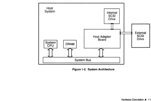
The host adapter plugs into a host system and supports the attachment of internal SCSI drives or the connection to external SCSI peripheral devices in add-on enclo-sures. The system architecture is illustrated ill Figure 1-2.
Host
System Internal
SCSI Drive
U
External
Host Ad1ter SCSI
Boar Drive
I
SystemI I
DRAMI
CPU~ )0. """I I"- ~
I"-..
~...
..
~ [image:19.613.73.560.437.762.2]I
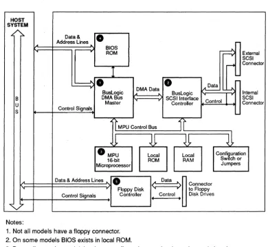
System BusFigure 1-3 is a functional block diagram of the BusLogic adapter. The paragraphs that follow describe the numbered components in the figure.
HOST SYSTEM
.t. ~
Data &
•
Address Lines ... BIOS ,ROM
r==¢
ExternalSCSI
...
Connector•
•
r-BusL~ic DMA Data BusLogic
~
....l\ Internal Control1
8 DMABus ...
" SCSI Interlace SCSI U Master Controller Connector S Control Signals
'I
MPU Control Bus1i
~~
~
JJ
~
8
MPU Local Local Configuration Swttch or 16-bit ROM RAMMicroprocessor Jumpers
... Data & Address Lines
•
< .
O~ ~
>
Connector,
Floppy Disk to FI py Control Signals Controller Control Disk "8rives
f •
V
Notes:
1. Not all models have a floppy connector. 2. On some models BIOS exists in local ROM.
3. Depending on the model, hardware configuration may be done via a switch or jumpers.
Figure 1-3. Host Adapter Architecture
Bus Master DMA Controller
All host bus interface logic is provided on the board by a BusLogic designed bus master ASIC O. This chip provides bus master capabilities which greatly reduce the involvement of the host system's CPU in I/O control and data transfer activi-ties. Under control of this chip, 32-bit bus master transfers at up to 132 MBytes/ sec to and from the main system memory are possible with the use of its intemal128-byte FIFO. A true multitasking mailbox structure supports up to 255 tasks. This performance and improved bus utilization significantly enhances multitasking and multi-user applications.
Advanced SCSI Controller
On-board control of the interface to SCSI peripheral devices is provided by another ASIC, the BusLogic SCSI controller chip @. Up to 10 MBytes/sec synchronous and
7 MBytes / sec asynchronous 8-bit SCSI data transfers are supported by the SCSI in-terface controller. This low-power, high-performance CMOS component com-pletely conforms to the ANSI standard, X3.131-1986 for the Small Computer System Interface. The chip reduces protocol overhead by performing common SCSI algorithms or sequences in response to a single host system command.
Microprocessor Unit (MPU)
Local BIOS ROM
An on-board, 16 .. Nt Intel-based 8018X microprocesSor unit (MPU) @ coordinates all activity on the host adapter under the direction of the board's local ROM. Con-sequently, the on-board MPU orchestrates such activities as the initialization, com-mand decoding, interrupt generation and the control of the data flow among the board's components.
The host adapter can be used in place of or in conjunction with a standard hard disk controller. The host adapter's on-board local BIOS 0 provides a compatible method of attaching a SCSI hard drive to a system just as any other type of hard disk is connected. The host adapter's BIOS intercepts each host software interrupt that requests a disk I/O service and manages these interrupts according to the ad-dress of the requested drive. If the designated drive is a disk assigned to the sys-tem's internal disk controller, the host adapter's BIOS passes the command on to that disk controller. If the designated disk is one of the SCSI disks attached to the host adapter, the host adapter's BIOS responds to the request and instructs the host adapter to execute the command.
Floppy Disk Controller
On models with a floppy controller, a floppy disk controller chip 0 provides sup-port for any combination of up to two 3.5" and 5.25" floppy disk drives with 250 KBytes/sec,300
KBytes/sec
and 500 KBytes/sec data transfer rates. On Model C boards, it can also support the newly emerging 2.88 MB floppies with transfer rates of 1 MBitl sec. This floppy controller circuitry is completely independent from the SCSI logic and is accessed by the system BIOS floppy diskette routines.Host DMA Data Transfer Control
ISA
EISA
A typical PCI AT system provides seven direct memory access (DMA) channels. One of the DMA Channels 5, 6, or 7 can be used by the ISA host adapter as defined by the on-board configuration. ChannelS is the default DMA channel. Whenever the ISA host adapter must transfer 16-bit data to or from memory, it performs a pri-ority arbitration process with other system DMA channels to obtain pennission to use the system bus. It asserts its DMARequest signal (Default DRQ5) and waits for the corresponding DMAAcknowledge signal (Default DACK5) to arbitrate for the bus. Once it obtains ownership of the bus, it asserts the -MASTER signal and op-erates as a bus master. It then transfers data across the bus directly into or out of the main system memory until the Time On Bus period has expired or the transfer
has been completed, whichever occurs first. If the transfer was not completed, the ISA host adapter will wait for the specified Time Off Bus period and then will ar-bitrate for bus access to resume the data transfer.
VESA
pel
All bus master mode data transfers, fucluding mailboxes, CCBs and SCSI periph-erals data are performed via the 32-bit, high-speed VL-Bus. Whenever the VESA host adapter has to transfer this data, it performs an arbitration process to obtain permission to use the VL-Bus. It asserts its slot-specific VL-Bus request signal (-LREQ) arid waits for the slot-specific VL-Bus grant signal (-LGNT). Once -LGNT is asserted, the board is granted ownership of the VL-Bus. It then transfers data across the VL-Bus directly into or out of the host memory until the allowed TIme On Bus period has expired, or the transfer has been completed; whichever occurs first. If the transfer was not completed, the VESA host adapter will arbitrate for bus access again to resume the data transfer.
The OMA control logic manages bus arbitration and data transfer coordination. The BT-946C operates as a PCI bus master during data transfers. The BT-946C ar-bitrates for PCI bus access and, once granted, it takes over control of the bus. It
generates the PC! bus address and command strobes. The BT-946C supports both odd and even starting addresses, commonly known as aligned and unaligned transfers. If presented with an even transfer count beginning at an odd memory starting address, the BT-946C will first transfer a single byte (data bits 024-031). The remaining data is then transferred as double words (32 bits) until the last byte, which is transferred as a single byte (data bits DO-07). While odd·byte transfers are fully supported, it is recommended that when possible, PCI host buffers be double-word aligned to gain better data transfer performance.
Hardware Registers
The host adapter's I/O interface consists of three hardware registers that are used by the host to issue start commands to the host adapter, to gain status information about the adapter's operation, and to manage interrupts generated by the host adapter. These registers are located in the I/O address space at three consecutive addresses. The beginning or base address is determined by the 110 base address switch settings described in the host adapter user's guide. Table 1-1 provides a summary of these 8-bit wide registers ..
Table 1·1. Host Adapter Hardware Registers
Address 'TYpe Description
va
Base Address + 0 W Control Register1/0 Base Address + 0 R Status Register
va
Base Address + 1 W CommandlParameter Reg ister1/0 Base Address + 1 R Data In Register
va
Base Address + 2 R Interrupt RegisterControl Register (Write Only) 1/0 Base Address + 0
2
1Hard Reset (RHARD)
-.J
I I
Soft Reset (RSOFT)Interrupt Reset (RINT)
I
SCSI Bus Reset (RSBUS) - - - '
Figure 1-4. Control Register (Write)
o
I
I
Reserved (Set to Zero)
The host system's CPU uses this register to specify programmable options within the host adapter (e.g., soft reset, hard reset, SCSI bus reset). For example, the host system's CPU can stop all host adapter activity immediately by setting this regis-ter's Bit 6, the Soft Reset bit (RSOFf). This is a write-only register.
Bits 0-3-These bits are reserved and must be set to zero.
Bit 4 Reset SCSI Bus (RSBUS)-When this bit is set to a one, the Reset signal on the SCSI bus is maintained true for at least 25 microseconds. This Reset condition im-mediately clears all SCSI devices from the bus. The assertion of the SCSI Reset con-dition supersedes all other activity on the SCSI bus. See the heading "Reset Operations" later in this section for additional details on the Reset operation.
Bit 5 Reset Interrupt (RINT)-The system's CPU sets this bit to acknowledge a host adapter interrupt. When this bit is set to one by the CPU, the host adapter's hard-ware-generated interrupt is reset and the Interrupt Register is cleared. Note that all bits in the Interrupt Register are cleared by setting this bit.
Bit 6 Soft Reset (RSOFf)-When this bit is set to one, it causes all host adapter activ-ity to stop immediately. All mailboxes, command control blocks, and any pending commands are discarded by the host adapter. Previous mailbox pointers must be cleared by host processes. The primary difference between a hard and soft reset is that this bit does not effect a SCSI Bus Reset condition. Once the soft reset activity has been completed by the host adapter, the host adapter must be reinitialized for any future operation. This state is indicated by the setting of the Host Adapter Ready bit (HARDY) and the Initialization Required bit (INREQ) in the Status Register.
Bit 7 Hard Reset (RHARD)-The setting of this bit causes the host adapter to enter an initial condition power-on state. Any command in process is stopped and pend-ing commands are abandoned. The host adapter will execute its internal diagnos-tic function and report any errors. During reset, the Diagnosdiagnos-tic Active bit (DACT) is set. Once the hard reset activity has been completed by the host adapter, the host adapter must be reinitialized for any future operation. This state is indicated by the setting of the Host Adapter Ready bit (HARDY) and the Initialization Required bit (INREQ) in the Status Register.
Status Register (Read Only) 110 Base Address
+0
Diagnostic Active (DACT) ,
I I
Diagnostic Failure (DFAIL)
Initialization Required (INREQ)
Host Adapter Ready _ _ _ _ _ --1
(HARDY)
~
L -Command Invalid(CMDINV) _ _ _ _ Reserved
(Undefined)
Data in Register Ready (DJRRDY) '--_ _ _ Command/Parameter Out
Register Busy (CPRBSY)
Figure 1-5. Status Register (Read)
The host adapter uses this register to report the status of its condition to the sys-tem's CPU.·For example, the host adapter sets this register's Data In Register Ready bit (DIRRDY) when it has written data to its Data In Register. By setting this bit, the host adapter notifies the host system's CPU that there is fresh data in the Data In Register that should be read. As soon as the host system's CPU reads the Data In Register, the host adapter immediately resets the Data In Register Ready bit (DIRRDY). The host adapter resets this bit to zero to ensure that the host sys-tern's CPU does not reread the same data in the Data In Register. When the host adapter writes fresh data to its Data In Register, it will then set the Data In Register Ready bit (DIRRDY) to one again.
The host system's CPU can also read this register to check for error conditions. For example, the host adapter sets this register's Command Invalid bit (CMDINV) when it detects an invalid command or parameter byte in its Command/Parame-ter RegisCommand/Parame-ter. Consequently, the host system's CPU can check the Command Invalid bit (CMDINV) to see if such an error condition currently exists. This is a read-only register.
Bit 0 Command Invalid (CMDINV)-The host adapter sets this bit immediately upon detection of an invalid command or parameter byte in the Command/Pa-rameter Register. When the host is sending a single or multibyte command, the host adapter terminates the data transfer sequence by setting the Command Com-plete bit (CMDC) in the Interrupt Register and by generating a hardware interrupt. The host adapter terminates all commands (valid or invalid) by this method.
In-valid commands are indicated by the setting of this bit. The condition of this bit is only meaningful while the Command Complete bit (CMDC) is true.
Bit 1 This bit is reserved and is set to zero.
Bit 2 Data In Register Ready (DIRRDY)-This status bit is used to synchronize the transfer of status infonnation from the host adapter to the host system. The host adapter sets this bit to one when it has placed a byte of data in the Data In Register. This condition notifies the host that it may read and process the data. When the host reads the data byte in the Data In Register, this bit is reset to zero by the host adapter. This sequence is repeated for multibyte data transfers.
Bit 3 Command/Parameter Register Busy (CPRBSY)-This status bit is used to synchronize the transfer of command and associated parameter bytes from the sys-tem host to the host adapter. When this bit is reset to zero the host may place a com-mand or parameter byte in the Comcom-mand/Parameter Register. When the host writes a byte to the Command/Parameter Register, the host adapter will set this
bit to a one indicating a Busy condition. The host adapter will reset this bit when it has read and processed the command/ parameter byte. This sequence is repeated for multibyte data transfers.
Bit 4 Host Adapter Ready (HARDY)-This bit indicates the ready or not ready in-ternal command state of the host adapter. When this bit is set, the host adapter is ready for a new host adapter command. In general the host system's processor may only issue host adapter commands while this bit is set.
Note:
The multitasking design of the host adapter's firmware permits the following
com-mands to be issued regardless of the busy or not-busy state of the host adapter.
• Start SCSI (02) command
• Enable Outgoing Mailbox Ready Interrupt (05) command. See Section 1-3, "Software Interface," for details on these commands
Bit 5 Initialization Required (INREQ)-When this bit is set to one, it indicates that the mailbox structures must be initialized. This bit is typically set immediately af-ter the completion of self-diagnostic tests following a reset. This bit is not set if di-agnostics fail (the Diagnostic Failure bit (DFAIL) is set). The host system must now issue an Initialize Mailbox command (01) to inform the host adapter of the base memory address of the mailbox structure area. The host adapter will reset this bit after successful completion of the Initialize Mailbox command.
Bit 6 Diagnostic Failure (DFAIL)-When this bit is set, it indicates that the host adapter's internal self diagnostic has detected an error. This bit may be reset only by a hard reset initiated either by hardware or by the host software. See Section 1-6, "Internal Diagnostics," for more details.
Bit 7 Diagnostic Active (DACT)-This bit is set when the host adapter begins its self-testing activity immediately after a power-on reset or a programmed hard re-set (Control Register, Bit 7 is re-set). This bit is rere-set upon the successful completion of the self-test activity. If the diagnostics fail, this bit may not be reset indicating that the self-test programs could not be completed. In the case of most failures, the Diagnostic Failure bit (DFAIL) will also be set. See Section 1-6, "Internal Diagnos-tics," for more details.
Command/Parameter Register (Write Only)
1/0
Base Address + 17
6
5
4
3
2
1
o
Command/Parameter Register
Figure 1·6. Command/Parameter Register (Write)
opera-tion may occur along with the cessaopera-tion of command acceptance by the host adapt-er. This· condition is indicated by the setting of the Command Invalid bit (CMDINV) in the Status Register.
The coordination of command and parameter data byte transfers between the host adapter and the host system is governed by the Host Adapter Ready bit (HARDY), the Command/Parameter Register Busy bit (CPRBSY), and the Data In Register Ready bit (DIRRDY). All host adapter commands, with the exception of Enable OMBR Interrupt (05) and Start SCSI (02), require the Host Adapter Ready bit (HARDY) to be set. Parameter data bytes are written to the Command/Parameter Register. The hos,t must first test the Command/Parameter Register Busy bit (CPRBSY) for a not set condition to determine if the host adapter is ready to accept a commarid parameter data byte. When the host writes a command or parameter byte to the Command/Parameter Register, the host adapter sets the Command/ Parameter Register Busy bit (CPRBSY) to a one. When the local MPU has read the byte, the·host adapter will reset the Command/Parameter Register Busy bit (CPRBSY) to indicate that the host can write another byte.
When all the bytes for a particular command have been transferred, and the com-mand has been completed, the host adapter will set the Command Complete bit (CMDC) in the Interrupt Register. If an error is detected in the command, the Com-mand Invalid bit (CMDINV) will be set in the Status Register.
Data In Register (Read Only)
1/0Base Address
+1
7 6 5 4
l
3 2 1 0Data In
Figure 1-7. Data In Register (Read)
The host adapter uses this register to return information bytes to the host system. For commands that return information bytes to the host, the Data In Register Ready bit (DIRRDY) is used to synclu:onize data byte transfers. The host adapter sets the Data In Register Read y bit (DIRRDy) to a one when a data byte is available to be read by the host system. The Data In Register Ready bit (DIRRDY) is auto-matically reset to zero by the host adapter when the host system reads the data byte from the host adapter's Data In Register. For multiple data byte transfers, the host should wait for the Data In Register Ready bit (DIRRDY) to return to the set state before reading additional data. When the last byte of an information block (single or multiple byte) has been transferred, the host adapter will set the Com-mand Complete bit (CMDC) in the Interrupt Register. This is a read-only register.
Interrupt Register (Read Only) 1/0 Base Address + 2
171
6 5 4 3 2 1a
Interrupt Valid ~ (INTV)
Reserved
SCSI Reset State _ _ _ _ _ _ --' (RSTS)
~
IUncoming
MailboxLoaded (IMBL) Mailbox Out Ready
(MBOR) Command Complete
(CMDC)
Figure 1-8. Interrupt Register (Read Only)
The host adapter uses this read -only register to tell the host system the reason why it generated a hardware interrupt signal. The following are the four conditions un-der which the host adapter can generate a hardware interrupt to the host system:
1. Incoming Mailbox Loaded interrupt (IMBL): the host adapter has made an en-try in an incoming mailbox.
2. Mailbox Out Ready interrupt (MBOR): an outgoing mailbox location(s) is ready for the host system to use.
3. Command Complete interrupt (CMDC): the host adapter has completed a com-mand.
4. SCSI Reset State interrupt (RSTS): the host adapter has detected a SCSI Bus Re-set condition.
When the host adapter generates a hardware interrupt signal for one of the preced-ing four reasons, the host adapter sets bits in this register to provide the host sys-tem with more information about the interrupt. The host adapter completes the following actions:
. 1. It sets Bit 7, the Interrupt Valid bit (INTV), to indicate that the interrupt is valid. 2. It also sets one of the other unreserved bits to indicate why it generated a
hard-ware interrupt signal to the host system. These bits (Bits 0-3) are collectively re-ferred to as interrupt cause bits. This group of bits include the Incoming Mailbox Loaded bit (IMBL), the Mailbox Out Ready bit (MBOR), the Command Complete bit (CMOC), and the SCSI Reset State bit (RSTS).
In response to this interrupt request by the host adapter, the host system should execute the following sequence to service the interrupt:
1. Read the Interrupt Register. The host should maintain this value internally for further interrupt processing.
2. Clear the Interrupt Register. This is accomplished by setting the host adapter's Control Register's Reset Interrupt bit (RINT).
3. Determine the interrupt cause (from the saved Interrupt Register value in the preceding Step 1) and then execute the appropriate interrupt service routine.
The host adapter sets the priority of certain interrupt conditions. This topic will be discussed before describing the individual bits of the Interrupt Register. Refer to the following heading "Interrupt Tnning and Synchronization."
Interrupt Tlnting and Synchronization. The host adapter sets the priority of certain interrupt conditions. The posting of a mailbox-related inteITIlpt is withheld if a SCSI Reset State interrupt (RS1S) or a Command Complete inteITIlpt (CMOC) is pending service from the host. Once the SCSI Reset State inteITIlpt (RS1S) or the Command Complete interrupt (CMOC) is cleared, the host adapter will post the mailbox inter-rupt(s). Likewise, a SCSI Reset State interrupt (RS1S) or a Command Complete in-terrupt (CMOC) will only be presented if the Inin-terrupt Register has been cleared, and the Data In Ready bit (DIRRDY) shows no additional data is pending.
Because all outbound host mailboxes are typically controlled by host-resident soft-ware, it is not necessary to enable the Outgoing Mailbox Ready interrupt (OMBR) unless all mailboxes are being utilized. This technique also lessens the possibility of missed interrupt notification for an Incoming Mailbox Loaded (IMBL) condi-tion. If all outgoing mailboxes are in use, then the host could enable the Outgoing Mailboxes Ready interrupt (OMBR) to gain notification of a Mailbox Ready condi-tion. See the Enable Outgoing Mailbox Ready command description in Section 1-3, "Software Interface," for instructions on how to enable the Outgoing Mailboxes interrupts (OMBR).
Bit 0 Incoming Mailbox Loaded (IMBL)-When this bit is set, it indicates that the host adapter has made an entry in an incoming mailbox location. This bit is quali-fied by the Interrupt Valid bit (INTV) also being set and by the generation of a bus interrupt Signal. The host should service this interrupt as soon as possible to allow . additional host adapter interrupts to be posted. The multitasking firmware of the host adapter continues to process outstanding SCSI commands after the posting of an Incoming Mailbox Loaded interrupt (IMBL). If ad(litional outstanding com-mands are completed before the servicing of a previous Incoming Mail~ox Loaded interrupt (lMBL), the status of completed commands Will be placed in an available incoming mailbox location. The host should therefore scan all mailboxes to deter-mine if additional data has been provided. The host adapter will use Incoming Mailbox locations in a round-robin orderpennitting the host to scan in the same manner. When a vacant mailbox is found the host may discontinue its scan.
Bit 1 Outgoing Mailbox Ready (OMBR)-When this bit is set to a one, it indicates that one or more of the outgoing mailbox locations is available for use by the host. This bit is qualified by the Interrupt Valid bit (INTV) also being set and by the gen-erationof a
bus
interrupt signal. The Outgoing Mailboxes Ready inteITIlpt (OMBR) is generated only when Outgoing Mailbox interrupts (OMBR) have been enabled and an outgoing mailbox entry is cleared by the host adapter. An Outgoing Mail-box Ready interrupt (OMBR) is suppressed if a SCSI Reset State (RS1S) or a Com-mand Complete (CMDC) interrupt is pending service. When these previous interrupts are cleared by the host, the ~nding Outgoing Mailboxes Ready inter-rupt (OMBR) ~l be issued by the hos,t adapter.Application Note: It is recommended that the Outgoing Mailbox Ready inteITIlpt (OMBR) riot be enabled unless all outgoing mailbox locations are in use. For most applications, the host adapter will process command requests faster than a host will issue them. If the situation, does o~cur where all outgoing mailbox locations are busy, the hos~ may issue the Enable Outgoing Mailbox Ready Interrupt com-mand without waiting for the status of the Host Adapter Ready bit (HARDY).
Bit 2 Command Complete (CMDC)-This bit is set to a one when the Command/ Parameter Register is ready to accept a command. Any previous command will have been completed, either normally or abnormally. If a previous command com-pleted with an error condition or was aborted for any reason, this bit will still be set along with the Command Invalid bit (CMDINV) in the Status Register. Normal-ly completed commands are indicated by the setting of this bit without any accom-panying error condition status bits. This bit is qualified by the Interrupt Valid bit (INTV) also being set and by the generation of a bus interrupt signal. A Command Complete interrupt (CMOC) is suppressed if an Interrupt Valid bit (INTV) is set (indicating an interrupt is pending service) or if the Data In Register Ready bit (DIRRDY) is set. When these previous interrupts are cleared by the host, the tem-porarily withheld Command Complete interrupt (CMDC) will be issued by the host adapter.
Bit 3 SCSI Reset State (RSTS)-When this bit is set, it indicates that a SCSI Bus Re-set condition has been detected by the host adapter. This bit is qualified by the In-terrupt Valid bit (INTV) also being set and by the generation of a bus hardware interrupt signal. In cooperation with host system driver software, the host adapter can implement the SCSI specification soft reset option. host adapter queued oper-ations will resume once the SCSI bus has returned to the operational state. If a cur-rently running command was aborted due to the SCSI Bus Reset condition, the host adapter may have to restart the command.
The host may convert the SCSI bus soft reset to a SCSI bus hard reset by setting the Soft Reset bit (RSOFI) in the host adapter's Control Register. In this case, all queued commands are abandoned and the host adapter must be reinitialized. See the head-ing "Reset Operations" later in this section for details on the reset conditions.
Bit 4 Reserved-Value read is zero.
Bit 5 Reserved-Value read is zero.
Bit 6 Reserved-Value read is zero.
Bit 7 Interrupt Valid (INTV)-When this bit is set, it indicates that a valid interrupt has been generated by the host adapter. This bit reflects the state of the host adapt-er genadapt-erated intadapt-errupt signal on the bus. The specific reason for the intadapt-errupt con-dition is determined by Bits 0-3 of this register.
Reset Operations
Host adapter reset conditions are initiated from two different vantage points: the host system and the SCSI bus. A description of each follows.
Host-Initiated Reset Operations
The host system may reset the host adapter to an initial power-on condition through two different operations, one system and the other software.
Software Reset-The host adapter may be fully reset to an initial state by a software command, just the same as if a system reset had been received by setting the Hard Reset bit (RHARD). When RHARD is set to true, a Reset condition occurs imme-diately. However, this Reset condition 'Yill only affect
one
host adapter, unlike the system reset (described above) which resets all host adapters installed in the system bus. An RHARD reset may issue a subsequent reset to the SCSI device de-pending on the AutoSCSI utility configuration setting for the Enable SCSI Bus Re-set option (see the manual for your host adapter for more information).Either type of host-initiated reset will cause the following conditions on the host adapter.
• The control registers of all intelligent logic modules on the host adapter will be initialized to a known state.
• All pending operations are aborted and all data structures are initialized to a no operation pending state.
• The host adapter executes all internal diagnostic functions. While the diagnos-tic functions are in process, the host adapter will indicate this condition by set-ting the Diagnostic Active bit (DACT) to true in the Status Register.
• During a system reset, the host adapter places a SCSI Bus Reset condition on the SCSI bus. This may also occur during a software reset (using the RHARD bit) , but depends on the AutoSCSI utility configuration setting for the Enable SCSI Bus Reset option. This will reset all peripheral devices, whether a target or ini-tiator.
• ~ter completion of a system reset, the host adapter indicates that it is now in an initial condition by asserting the Initialization Required bit GNREQ) in the host adapter's Status Register. This condition requires that all mailbox, com-mand control blocks, and host adapter operation parameters be established be-fore operations may begin.
Note: The host mqy intiate a soft reset
by
setting the RSOFT bit. This reset reinitializes
the specific host adapter, but there is no subsequent SCSI bus reset.
SCSI Bus Reset Operations
The SCSI Bus Reset condition is used to clear all SCSI devices immediately from the SCSI bus. When the SCSI bus Reset signal is asserted, the SCSI Bus Reset con-dition takes precedence over all other bus phases. A SCSI Bus Reset condition may be forced by any device on the bus, whether a target or initiator. Whenever a SCSI Reset condition occurs, a Bus Free phase always follows the Reset condition.
The five ways in which a SCSI bus reset may be either asserted or sensed by the host adapter are as follows:
Rl The SCSI Bus Reset condition is always asserted when the host adapter is
re-set by the host system (host system system rere-set only). This is described ear-lier in this section under the heading "Host-Initiated Reset Operation."
R2 The SCSI Bus Reset condition may be asserted when the host adapter is soft reset by the host system when RHARDis set to true (depending on the Au-toSCSI utility configuration setting for the Enable SCSI Bus Reset option). This is also described under the heading "Host-Initiated Reset Operations."
R3 The SCSI Bus Reset condition is asserted if the Reset SCSI Bus bit (RSBUS) is set by the host system control software.
R4 The host adapter may initiate a SCSI Bus Reset condition in reaction to
a
detected bus phase error. The host adapter constantly monitors the SCSI bus for invalid conditions. If an invalid phase is detected, the host adapter will perform a normal SCSI Bus Reset operation which includes the asser-tion of the SCSI bus Reset signal.R5 The host adapter will detect and respond to a SCSI Bus Reset condition that is asserted by another device on the bus. Other SCSI devices may normally assert the Reset signal during either initialization or certain error recovery states. The device driver requires an acknowledgement from the host adapter that a SCSI Reset operation has taken place, so the SCSI Reset State bit is set in the interrupt register.
While the SCSI specification defines two methods by which the SCSI bus may be reset, either by the hard reset option or the soft reset option,
BusLogic host adapters
only support the hard reset option.
The SCSI bus hard reset option restores ALL SCSI devices, target or initiator, to the initial power-on condition. All system activity is lost, and all devices must be com-pletely reinitialized before normal operations may be restored. SCSI devices that implement the hard reset option perform the following operations:
• Clear all uncompleted commands. • Release all SCSI device reservations.
• Return any SCSI device operating modes to their default condition.
Here is how the host adapter implements a SCSI hard reset:
• When the host adapter detects a SCSI reset, it issues an interrupt indicating a SCSI reset has occurred to the host system.
• The host adapter sets both the SCSI Reset State bit (RSTS) and the Interrupt Val-id bit (INTV) in the host adapter's Interrupt Register.
• All host adapter command control blocks (CCBs) are abandoned and the host adapter readies itself to accept new initialization commands.
• BusLogic recommends that after the device driver receives the RSTS, it issue a RHARD or an RSOFf to ensure that the host adapter is re-initialized.
Software Interface
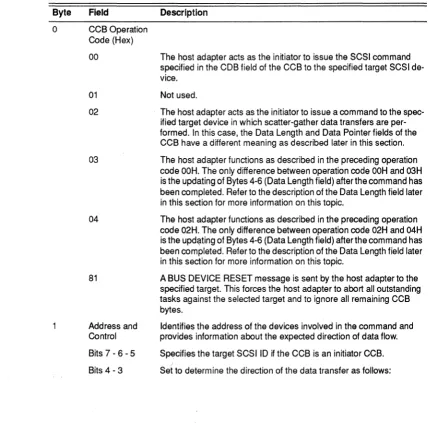
For the host adapter to operate properly, the host system must issue the correct command and associated parameters to the host adapter. The host adapter has its own set of executable instructions that the host system can issue to the host adapt-er. This command set can be subdivided into the following three groups:
1. Host adapter commands
2. Mailbox commands
3. BIOS commands
The host system uses the host adapter commands to initialize and to establish con-trol specifications for subsequent operations of the host adapter. The host system uses the host adapter's Command/Parameter Register as an input port through which it issues any host adapter commands and associated parameter bytes to the host adapter. For more details on each of these host adapter commands refer to the heading "Host Adapter Commands" later in this section.
The second category of commands, mailbox commands, is issued to the host adapter when multithreaded operations are required. Mailboxes are reserved stor-age areas which reside at a fixed contiguous memory location in the host system's main memory. The mailboxes coordinate communications between the host sys-tem and the host adapter when the host adapter is operating in multithreaded mode. This software interface enables the host adapter to execute multiple com-mands concurrently for multiple targets withminirnal intervention from the host system. For more details on these mailbox commands refer to the heading "Mail-box Commands" later in this section.
The third category of commands, BIOS commands, is issued to the host adapter when single-threaded operations are required. In this case the BIOS commands work with the host adapter's on-board BIOS. These commands in unison with the on-board BIOS function in a manner fully compatible with DOS and the standard BIOS interface as defined in the host system's technical reference manual. For more details on each of these BIOS commands refer to the heading ''BIOS Command In-terface" later in this section.
Bus Master Direct Memory Access (DMA)
The DMA control logic manages bus arbitration and data transfer coordination. The host adapter operates as a bus master during data transfers. The host adapter arbitrates for bus access and once granted, it takes over control of the bus. It gen-erates the bus address and command strobes. The host adapter supports both odd and even starting addresses, commonly known respectively as aligned and un-aligned transfers. If presented with an even transfer count beginning at odd mem-ory starting address, the host adapter will first transfer a single byte (data bits 024-D31). The remaining data is then transferred as double words (32 bits) until the last byte which is transferred as a single byte (data bits DO-D7). While odd byte data transfers are fully supported, it is recommended that when possible host buffers
be double-word aligned to gain better data transfer performance.
Interrupt Processing
Several interrupt channels are available to the host adapter. The channel to be used by each host adapter board is specified by configuration settings as described in the host adapter user's guide.
The host system contains a programmable interrupt controller which receives all
interrupts and directs the host's CPU to a corresponding vector location which in
turn contains a memory address for the software Interrupt Service routine which performs the necessary actions required by each interrupt. It also contains a Mask Register whose bits may be set to mask or cleared to permit corresponding inter-rupt channels to be acknowledged.
In order to respond correctly to host adapter interrupts during normal operation, the host interrupt controller must be programmed appropriately. The software driver will have to program the host's Interrupt Mask Register and interrupt vec-tor before attempting to use interrupts from the host adapter. The interrupt vecvec-tor locations and Interrupt Mask Register's bits which need to be cleared to permit ac-knowledgment of each interrupt channel are listed as follows:
Vector location Interr1ct Mask Register Hardware Interrupt Line In Memory (Hex) Hex A dress A1
IR09 1C4-1C7 Bit 1
IR010 1C8-1CB Bit 2
Default IR011 1CC-1CF Bit 3
IRQ12 100-103 Bit 4
IR014 108-lOB Bit 6
IR015 lOC-lOF Bit 7
If the host adapter is configured for Interrupt Channel 11, for example, the sys-tem's interrupt controller must be initialized by clearing Bit 3 in its Interrupt Mask Register. The address of the interrupt service routine for Channel 11 will be con-tained in the four bytes of memory beginning at memory address 1 CCH.
The remainder of this section describes the structure and operation of the three cat-egories of commands that the host can issue to the host adapter.
•
Host Adapter Commands
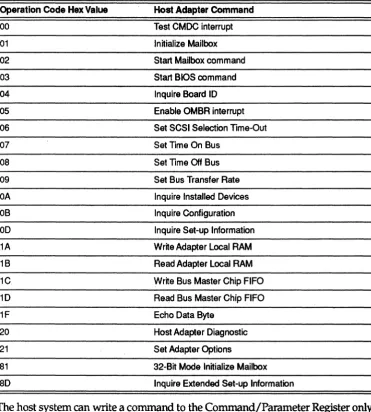
[image:35.615.190.562.136.548.2]Host adapter command codes and associated parameter bytes are supplied to the host adapter's Control Register under the coordination of certain bits in the host adapter's Status Register. Table 1-2 provides a summary of these commands.
Table 1·2. Host Adapter Commands
Operation Code Hex Value Host Adapter Command
00 Test CMDC interrupt
01 Initialize Mailbox
02 Start Mailbox command
03 Start BIOS command
04 Inquire Board 10
05 Enable OMBR interrupt
06 Set SCSI Selection Time-Out
07 Set Time On Bus
08 Set Time Off Bus
09 Set Bus Transfer Rate
OA Inquire Installed Devices
OB Inquire Configuration
00 Inquire Set-up Information
1A Write Adapter Local RAM
1B Read Adapter Local RAM
1C Write Bus Master Chip FIFO
10 Read Bus Master Chip FIFO
1F Echo Data Byte
20 Host Adapter Diagnostic
21 Set Adapter Options
81 32-Bit Mode Initialize Mailbox
80 Inquire Extended Set-up Information
The host system can write a command to the Command/Parameter Register only after checking to see that the Host Adapter Ready bit (HARDY) is set to one, except that the Start Mailbox command and the Enable OMBR Interrupt command may be written at any time. After writing a command, the host may write a predeter-. mined number of parameter bytes to the Command/Parameter Register after
checking that the Command/Parameter Register Busy bit (CPRBSY) is
zero,
indi-cating that the Command/Parameter Register is not busy and can accept another parameter byte.The following table lists each host adapter command code along with the associat-ed number of parameter bytes coming into or being sent out from the host adapter and a brief description of the function performed.
Operation Code 00
Command
TEST CMDC INTERRUPT
Parameter Byte Count None
Direction None
Description. The host adapter's only response to this command is to set the Command Com-plete bit (CMDC) in the Interrupt Register. When this bit is set, the host can verify proper func-tioning of this bit.
Operation Code 01
Command
INITIALIZE MAILBOX
Parameter Byte Count
4
Direction Out
Description. This command specifies the number of mailboxes used by the host adapter, and the base memory location of the mailbox array to be used when executing mailbox commands. Four parameter bytes follow the command byte to provide the following information:
Byte Description
o
Number of mailboxes needed - must be greater than zero.1 - 3 Base mailbox address - specifies the location of the first byte of the mailbox ar-ray. Byte 1 is the most significant byte (MSB).
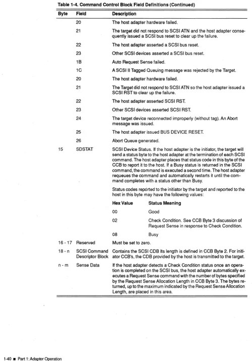
Each mailbox location in memory will occupy four outgoing mailbox bytes and four incoming mail-box bytes. The Command Invalid bit (CMDINV) will be set with the Command Complete bit (CMDC) if the number of mailboxes is specified as zero. At command completion, the Command Complete bit (CMDC) is set to one and the Initialization Required bjt (INREQ) is reset to zero to acknowledge that initialization is unnecessary. See the heading "Mailbox Commands" later in this section for more information on the mailbox structure.
Operation Code 02
Command
START MAILBOX COMMAND
Parameter Byte Count None
Direction None
Description. This command is normally issued every time the host makes an outgoing mailbox entry. Upon receipt of this command, the host adapter begins scanning for active outgoing mail-box entries and continues scanning until all outgoing mailmail-box entries have been serviced. This can be accomplished by either beginning the requested operations or queuing the commands and executing them later. To avoid unnecessary interrupt servicing by the host, the Command Complete bit (CMDC) is not set after receipt of this command. If this command is received before the Initialize Mailbox command, however, the host adapter will then set both the Command In-valid bit (CMDINV) and the Command Complete bit (CMDC) in the Status Register.
Operation Code ,Com'mand
03 START BIOS COMMAND
Parameter Byte Count None
Direction None
Description. This command is used exclusively by the host adapter's BIOS to communicate with the host adapter's firmware. This command is not used by application programs.
Operation Code
04
Command
INQUIRE BOARD ID
Parameter Byte Count
4
Direction In
Description. Upon receipt of this command, the host adapter sends four bytes of data to the host which contain identification and revision information about itself. Refer to these byte contents:
1-24 • Part 1 : Adapter Operation
Byte Description
Hex Value 41
42
Other
Meaning
Board is a BT-54X, BT-74X, BT-44X, or BT-946C with 64-head BIOS
Board is a BT-640A with 64-head BIOS Reserved
Custom Features - indicates what custom features may be supported by the host adapter.
Hex Value 41
Other
Meaning
Standard host adapter Reserved
2 Firmware Revision Level - a byte designating the revision level of the host adapt-er firmware. ASCII "0" - "9"
3 Firmware Version - a byte designating the revision level of the installed firmware
Once the four bytes of data have been transferred, the Command Complete bit (CMDC) is set indicating normal command completion.
Operation Code
05
Command
ENABLE OMBR INTERRUPT
Parameter Byte Count 1
Direction
Out
Description. This command specifies whether the Outgoing Mailbox Ready bit (OMBR) should be set when an outgoing mailbox entry is cleared by the host adapter. The single parameter byte from the host instructs the host adapter as follows:
Meaning Hex Value
00 01
The Outgoing Mailbox Ready Interrupt bit (OMBR) is notto be set. The Outgoing Mailbox Ready Interrupt bit (OMBR) is to be set once the outgoing mailbox has been cleared by the host adapter. To avoid unnecessary interrupt servicing by the host, the Command Complete bit (CMDC) is not set after receipt of this command. If the parameter byte contains a value other than OOH or 01 H, however, the Command Invalid bit (CMDINV) is set, as well as the Command Complete bit (CMDC), to indicate receipt of an invalid command.
Operation Code
06
Command Parameter Byte Count Direction
Out
SET SCSI SELECTION TIME-OUT 4
Description. This command specifies the wait time used to determine whether or not a SCSI se-lection was successful. If the SCSI Busy signal is not returned within the specified time-out peri-od, the selection will be terminated and the appropriate error message recorded in the returned CCB. The contents of the four parameter bytes received with this command are as follows:
Byte Description
o
Enable/Disable SCSI Selection Time-Out - specifies whether or not the SCSI Se-lection time-out is used. Refer to the following values.Hex Value Meaning
00 No time-out is performed.
01 The time specified in Bytes 02 and 03 is used as the SCSI time-out period.
Reserved - must be set to zero.
2 - 3 Time-Out Value - specifies the SCSI selection time-out period in milliseconds. The default value is 250 milliseconds. Byte 2 is the most significant byte.
Operation Code 07
Command
SET PREEMPT TIME ON BUS
Parameter Byte Count 1
Direction Out
Description. This·command specifies the time the host adapter is allowed on the bus after being preempted. One parameter byte is sent to the host adapter indicating the length of time in micro-seconds. This time can be from 2 to 15 micromicro-seconds. The default value is 7 micromicro-seconds. After command completion, the Command Complete bit (CMDC) is set indicating normal command completion. If the data byte value is greater than 15, the Command Invalid bit (CMDINV) is set indicating that an invalid command was received.
When the host adapter requires a host data transfer, it asserts the Master (x) Request signal and waits for the host arbitration logic to respond with the Master (x) Acknowledge signal. Once it ob-tains ownership of the bus it then transfers data across the bus directly into or out of main system memory. The host adapter releases the bus when the transfer is completed within Preempt Time On Bus after a preempt condition (deassertion of the Master (x) Acknowledge signal).
Operation Code 08
Command
SET T1ME OFF BUS
Parameter Byte Count 1
Direction Out
Description. This command specifies the time the host adapter will spend off the bus. One pa-rameter byte is sent to the host adapter indicating the length of time in microseconds. This com-mand is treated as a no operation comcom-mand. It is supported for software compatibility to ISA software.
Operation Code
09
Command
SET BUS TRANSFER RATE
Parameter Byte Count 1
Direction Out
Description. This command is treated as a no operation command. It is supported for software compatibility to ISA software.
Operation Code
OA
Command
INQUIRE INSTALLED DEVICES
Parameter Byte Count
8
. Direction In
Description. This command asks the host adapter to indicate the devices connected to the SCSI bus. The host adapter issues the SCSI Test Unit Ready command to each target/Logical Unit Number (LUN) combination and reports the r.esults using eight bytes of data returned to the host through the Data In Register. Each byte has an associated target device; I.e., Byte 2 represents Target 2. If a bit has a value of one, the associated LU (Logical Unit) is installed. Each bit within a byte has an associated LU; i.e., Bit 3 represents LU 3, etc.
The byte associated with the host adapter will always be zero. Once all information has been transferred, the Command Complete bit (CMDC) is set to indicate normal command completion.
Operation Code
DB
. , -Command
INQWRECONRGURAT10N
Parameter Byte Count 3
Direction In
Description. The host adapter returns th'ree bytes of data describing the host DMA channel, the interrupt channel, and the SCSI ID values set during configuration set up.
Except for BusLogic ISA host adapters, BusLogic adapters do not use the ISA DMA channels but may still be required to support the ISA software command Inquire Configuration. This command requires the adapter to specify an ISA DMA channel which is used during host data transfers. ISA software programs the requested DMA channel to function in cascade mode and enables it to receive DMA requests. The adapter's response to the Inquire Configuration command is a con-figurable option described in the adapter user's guide. Most ISA software executes properly when the adapter specifies no DMA channel in response to this command. Some ISA software, how-ever, requires a specific DMA channel (DRQ5, DR06, or DR07) to be selected. Because the