warwick.ac.uk/lib-publications
Original citation:Al Hamd, Rwayda Kh. S. , Gillie, Martin, Warren, Holly, Torelli, Giacomo, Stratford,
Tim and Wang, Yong (2018)The effect of load induced thermal strain on flat slab behaviour at elevated 1 temperatures. Fire Safety Journal, 97. pp.
12-18. doi:10.1016/j.firesaf.2018.02.004
Permanent WRAP URL:
http://wrap.warwick.ac.uk/99181
Copyright and reuse:
The Warwick Research Archive Portal (WRAP) makes this work by researchers of the University of Warwick available open access under the following conditions. Copyright © and all moral rights to the version of the paper presented here belong to the individual author(s) and/or other copyright owners. To the extent reasonable and practicable the material made available in WRAP has been checked for eligibility before being made available.
Copies of full items can be used for personal research or study, educational, or not-for-profit purposes without prior permission or charge. Provided that the authors, title and full bibliographic details are credited, a hyperlink and/or URL is given for the original metadata page and the content is not changed in any way.
Publisher’s statement:
© 2018, Elsevier. Licensed under the Creative Commons
Attribution-NonCommercial-NoDerivatives 4.0 International http://creativecommons.org/licenses/by-nc-nd/4.0/
A note on versions:
The version presented here may differ from the published version or, version of record, if you wish to cite this item you are advised to consult the publisher’s version. Please see the ‘permanent WRAP URL’ above for details on accessing the published version and note that access may require a subscription.
1
The effect of load induced thermal strain on flat slab behaviour at elevated
1
temperatures
2
Rwayda Kh. S. Al Hamd*1, Martin Gillie2, Holly Warren3, Giacomo Torelli4, Tim Stratford5 and Yong Wang1 3
1 School of Mechanical, Aerospace and Civil Engineering, The University of Manchester, Manchester M13 9PL, UK 4
2 The School of Engineering, The University of Warwick, Coventry, CV4 7AL, UK 5
3 AECOM, One Trinity Gardens, First Floor, Quayside, Newcastle-upon-Tyne, NE1 2HF. 6
4 University of Cambridge Engineering Department Trumpington Street Cambridge CB2 1PZ 7
5 School of Engineering, The University of Edinburgh, Old College, South Bridge, Edinburgh, EH8 9YL 8
*Corresponding author: E-mail address: rwayda.alhamd@manchester.ac.uk. 9
1. Abstract
10
Several recent sets of experimental results on the punching shear behaviour of flat slabs in fire 11
have produced apparently anomalous deflections results, where the slab deflections on heating are 12
in the opposite direction to that expected if arising from free thermal expansion. Using numerical 13
analysis, this paper shows that the results are explained by load induced thermal strains (LITS). 14
Using two independent modelling approaches, the profound effect of LITS on deflection 15
behaviour is demonstrated. The findings have implications for the design of flat-slab structures 16
to resist fire because ignoring LITS may result in non-conservative design predictions. 17
2. Introduction
18
Flat plate concrete structures are an economical type of building commonly used for offices and 19
similar structures. They are easy to construct, offer flexible column arrangements and are 20
relatively cheap to build. However, they are susceptible to a type of failure known as “punching 21
shear” (Figure 1), where columns pierce floor slabs, leading to collapse. This is a particularly 22
dangerous type of failure as it is brittle and occurs suddenly. Punching shear occurring at high 23
temperatures, such as in fire, is a concern [1]. This condition has been studied experimentally, but 24
to date, there has been a little numerical investigation of the topic. This paper presents a numerical 25
study of the mechanics of punching shear failure at elevated temperatures, with a focus on the role 26
of load induced thermal strain (LITS), which is shown to explain some apparently anomalous 27
experimental results. 28
29
Figure 1 Schematic diagram of a flat plate structure and the punching shear failure mechanism. 30
After the car park collapse in Gretzenbach, Switzerland in 2004 due to fire [1], various 31
experimental studies investigated punching shear in heated slabs. These included Salem et al. [2], 32
Liao et al. [3] and Smith et al. [4–7]. All these studies took a similar approach of testing a portion 33
of the slab with a column stub attached, as indicated conceptually in Figure 2. Sometimes the slab 34
portions were simply-supported at their edges while in other tests in-plane restraint was applied 35
to simulate the rest of a larger structure. The gravity loading typical in real structures was 36
simulated by imposed displacements applied to the column stubs, which caused line-load type 37
reactions at the slab edges. After mechanical loading, heating from gas radiant panels or similar 38
systems was applied. 39
In all the above tests, and most clearly documented by Smith et al. [4–7], the deflections of the 40
2
2). A simple thermo-mechanical analysis suggests that when heated as described, deflections of 1
Smith’s slabs due to thermal expansion would be towards the heating source. The large thermal 2
gradient set up in the slab leading to thermal expansion on the lower surface would be expected 3
to result in a convex deflected shape as indicated Figure 2a. However, the observed experimental 4
deflections were in the opposite direction, resulting in a concave shape as shown in Figure 2b. 5
This finding could not be explained directly by the experimental results but was in line with the 6
work of Liao et al. [3] who observed the same effect. Kordina [8,9] also highlighted the combined 7
effects of load and thermally induced deflections in earlier tests. It is this previously unexplained 8
behaviour that the present study focuses on and explains using a numerical approach. It is found 9
that a strain component seen in heated concrete called load-induced thermal strains (LITS) 10
explains the behaviour. However, LITS is a complex and not fully understood the phenomenon 11
that presents difficulties for numerical models. Hence, the remainder of this paper is structured 12
as follows: 13
An overview of the phenomenon of LITS; 14
A presentation of the techniques used to model the experimental results of Smith with a 15
demonstration of the importance of LITS for explaining the observed behaviour; 16
A parametric study exploring the behaviour of different types of slab and heating 17
conditions; 18
Conclusion drawn from the results highlighting potential future work and design 19
implications. 20
21
[image:3.595.79.483.258.492.2]Expected deflection Experimental deflection
Figure 2 Conceptual arrangement for testing heated flat plate beam-column connections.
(a) Expected deflection response under heating and (b) Deflection response observed in Smith’s tests [4–6].
3. Load Induced Thermal Strain (LITS) and Transient Thermal Strain
22
A key aspect of the behaviour of heated concrete is LITS, a component of total strain. LITS is a 23
compressive strain that develops under combinations of temperature and compressive stress. The 24
precise definition of LITS is somewhat confused in the literature [10,11]. Here we adopt the 25
definitions used by Torelli et al. [11], who give the total strain, 𝜀𝑡𝑜𝑡, in concrete subject to both 26
stress and heating as 27
𝜀tot= 𝜀ela,0+𝜀th+ 𝜀lits 28
Where 𝜀ela,0 the elastic strain at ambient temperature, 𝜀th is the free thermal strain, and 𝜀𝑙𝑖𝑡𝑠 is the
29
LITS. LITS itself consists of several components 30
𝜀lits=∆𝜀ela+𝜀ts+𝜀cr 31
where ∆𝜀𝑒𝑙𝑎 is the change in elastic strain due to loss of elastic modulus on heating, 𝜀𝑡𝑠 is the 32
transient thermal strain and 𝜀𝑐𝑟 the basic creep strain that develops during heating. Here we will 33
not consider 𝜀𝑐𝑟 further as it is normally a small component of LITS [12]. Transient thermal 34
strain, the dominant portion of LITS, is largely irrecoverable (plastic) and only develops on first 35
3
LITS increases with both increasing compressive stress and increasing temperature [11]. Thus, 1
under suitable thermal and mechanical conditions, compressive LITS strains may be larger than 2
the expansive free-thermal strain and result in an apparent thermal contraction on first heating of 3
concrete (Figure 3), behaviour at odds with that of most materials and intuitive expectations. 4
Several analytical models have been proposed to represent LITS [13]. In this study, the model 5
proposed by Anderberg and Thelandersson [14] is adopted, in which the transient thermal strain 6
component of LITS in compression is given by: 7
εts= −ktr
𝜎
𝜎𝑢0𝜀𝑡ℎ for T ≤ 550 ℃
𝜕𝜀𝑡𝑠
𝜕𝑇 = −0.0001 (
𝜎
𝜎𝑢0) for 𝑇 > 550 ℃
where σu0 is the compressive strength of concrete at ambient temperature and ktr is a material 8
parameter. While this model has been criticised for not fully capturing all experimental results, 9
particularly at higher temperatures, it has the advantages of capturing general trends in behaviour 10
and avoiding many non-physically meaningful coefficients that alternative models contain. 11
[image:4.595.191.381.290.486.2]12
Figure 3 Typical LITS behaviour expressed as a function of temperature for different load levels. (Adapted 13
from http://dx.doi.org/10.1016/j.engstruct.2016.08.021 under Creative Commons License ). 14
4. Modelling Approach and Validation
15
The finite element package Abaqus was used in the majority of this study. To obtain a reliable 16
modelling approach for a single column and associated area of concrete floor slab in punching 17
shear (Figure 2), models were first developed and validated against ambient temperature 18
experimental results provided by Salman et al. [15–17] for punching shear, before high-19
temperature effects were introduced. 20
Salman performed tests of a similar scale and nature to those of Smith, but with a focus on ambient 21
temperature behaviour and these provided a comprehensive data set for model development. For 22
validation purposes, Salman’s test 1 (Figure 4 and Figure 5) was used. In this test, a concrete slab 23
with an associated column stub was loaded to failure with the load-deflection behaviour recorded 24
(Figure 7). 25
4
Figure 4 Dimensions and reinforcement details for Salman's test. 1
2
Figure 5 Salman’s [15] experimental setup. 3
This experimental setup was simulated using the finite element package Abaqus [30]. The 4
simulations used 8-noded hexahedral solid elements with reduced integration for all concrete parts 5
of the test specimens, together with truss (axial forces only) elements to represent the 6
reinforcement. Full mechanical bond between the two materials was assumed [18]. Concrete was 7
represented using the damaged plasticity model provided with Abaqus with the uniaxial 8
compressive stress-strain relationship taken from Eurocode 2 [19]. The main parameters used for 9
the damage plasticity model were taken from the literature [19] [20] [21] [22] and are shown in 10
Table 1. Steel behaviour was taken from measured behaviour in coupon tests and modelled using 11
a von Mises yield criterion. 12
Table 1 Concrete damge placicity parameters [19] [20] [21] [22] 13
Dilation Angle Eccentricity σb0⁄σc0 K Viscosity Parameter
40° 0.1 1.16 2/3 0
The results from this modelling approach are shown in Figure 7 for two cases, firstly when a Riks 14
solution procedure that can track softening behaviour was used and secondly when a general 15
quasi-static solver was used. Both show an excellent comparison with the physical behaviour thus 16
validating the modelling approach. For the high-temperature modelling work (below) the quasi-17
static solver was used as it can model temperature loading effectively. 18
[image:5.595.78.473.494.617.2]Model layout Boundary conditions
5 1
Figure 7 Load-deflection behaviour of Salman’s experimental results [23] and that predicted by numerical 2
simulations. 3
5. Elevated temperature modelling
4
The same modelling approach was then adopted to represent the high-temperature behaviour of 5
Smith’s slabs by introducing temperatures to the model in addition to the mechanical loading. This 6
was done in two steps. First, a thermal heat transfer model was developed to generate the thermal 7
profile for the slab. Next, this thermal profile was imported into the concrete part of the mechanical 8
model The reinforcement was assumed unheated in the mechanical model. However this will 9
have little effect on the results because reinforcement temperatures remain sufficiently low for 10
neither stiffness nor strength to be significantly affected. 11
Concrete behaviour at high temperature depends on various quantities. In this study, the variation 12
of Young’s modulus, compressive strength, tensile strength and thermal expansion of heated 13
concrete were all taken from Eurocode 2 ENV [24]. [25]. This (superseded) design code was used 14
because it contains a concrete stress-strain-temperature description where no attempt to include 15
the effects of transient thermal strain is included, which is what was required for this study (solid 16
lines in Figure 9). The code provides a range of strains for a given normalised stresses with the 17
lower bound of the range, not including the effects of transient thermal strain. [26,27] The current 18
version of the code does include the effects of LITS in a crude form, so it was not used. The 19
variation of plasticity parameters included in the concrete damage plasticity model was assumed 20
not to vary with temperature. 21
For an initial study, a slab that had simple supports at all edges (no vertical movement but free to 22
rotate) with a thickness of 75 mm was chosen (S75). Only tension reinforcement was present. 23
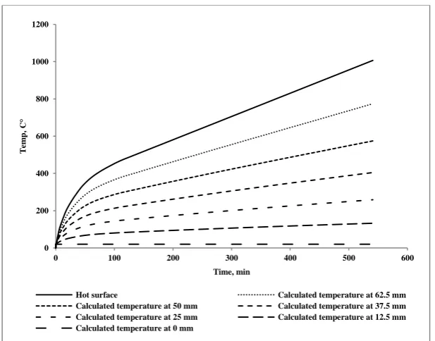
Heating was provided in Smith’s experiments by radiant panel heaters, with a peak surface 24
temperature of around 380⁰C being reached. The surface temperature in this slab was measured 25
by Smith ( 26
Figure 8) using thermal couples [7]. This data was used as an input to the numerical thermal 27
analysis that then predicted temperatures at all depths within the slab through time. This thermal 28
field was in turn introduced to the stress analysis model. 29
0 10 20 30 40 50 60 70 80
0 2 4 6 8 10 12 14 16
L
o
a
d
,
k
N
Deflection, mm
6 1
Figure 8 Temperature-time data for the heated surface adapted from Smith [7]. 2
3
[image:7.595.140.427.273.469.2]4
Figure 9 Stress-strain behaviour of concrete at various temperatures according to ENV (solid lines) and ENV 5
plus transient thermal strain (tts) (dashed lines). 6
It was found that simply introducing elevated temperatures together with the above material 7
properties to the ambient temperature model was not sufficient to reproduce Smith’s [4–6] 8
experimental results (Figure 10). Instead, a response as might be expected from a simple 9
consideration of thermal expansion was seen, as in Figure 2. 10
Next, an additional strain component was introduced so that LITS according to Anderberg and 11
Thelandersson [14] was captured numerically. This was done by adding transient thermal strain 12
components to the concrete stress-strain-temperature description (dashed lines Figure 9). With 13
this in place, the predicted deflections corresponded well with the experimental result for most of 14
the heating period (Figure 10), highlighting clearly the important effects of LITS on the deflection 15
response of this structure. 16
0 100 200 300 400 500 600
0 20 40 60 80 100 120
T
em
p
,
C
°
Time, min
Hot surface adopted from experiment Calculated temperature at 62.5 mm Calculated temperature at 50 mm Calculated temperature at 37.5 mm Calculated temperature at 25 mm Calculated temperature at 12.5 mm Calculated temperature at 0 mm
0 10 20 30 40 50 60
0 0.005 0.01 0.015 0.02 0.025 0.03 0.035
S
tr
ess
(M
Pa
)
Strain
20C 100C 200C 300C 400C
100C with LITS 200C with LITS 300C with LITS 400C with LITS
tts for given stress and temperature
7 1
Figure 10 Deflection-time response of Smith’s slab (S75), together with predicted numerical predictions for 2
concrete models without LITS (ENV) and with LITS (ENV+LITS). 3
To confirm these results were not a consequence of either a particular numerical code or an 4
anomalous experiment, another of Smith’s experiments was modelled with the finite element 5
package Code Aster. This experiment had no steel reinforcement and a 100 mm slab thickness 6
(S100). A similar material behaviour law incorporating elasticity, thermal expansion as well as 7
Anderberg and Thelandersson’s [14] LITS model was implemented and used to evaluate the 8
deflection of the slab when heated. As in the Abaqus model, significantly better deflection 9
predictions result when LITS is included (Figure 11). Together with the results in Figure 10, these 10
give a high level of confidence that the previously inexplicable experimental results are due to 11
LITS dominating deflections at high temperatures. 12
[image:8.595.134.434.404.592.2]13
Figure 11 Deflection-time response for the Code Aster model (S100). 14
6. Effect of higher temperatures and failure
15
The experimental work of Smith and others highlighted above-obtained results for lower surface 16
slab temperatures up to about 480 C°. The peak temperatures were limited by the heating 17
equipment available and are substantially below the temperatures that might occur in a real fire or 18
those that might cause slab failure. Therefore the behaviour of slabs subjected to higher 19
temperatures was studied numerically assuming two heating scenarios - “slow” and “fast” fires. 20
6.1.Slow fire
21
First, a “slow” fire was modelled. Here the initial temperature-time field measured by Smith was 22
included (as before) but extended by assuming a linear increase in temperature from the point at 23
which experimental measurements ceased (Figure 12). 24
-5 0 5 10 15 20 25 30 35 40 45 50
0 20 40 60 80 100 120 140
D
ef
le
ct
io
n
, m
m
Time, min
Experiment ENV ENV +LITS
0 5 10 15 20 25
0 10 20 30 40 50 60 70 80 90 100 110 120
D
ef
le
ct
io
n
, m
m
Time, min
8 1
Figure 12 Temperature-time data are assuming linear increases in temperature beyond the measured results 2
of Smith. 3
The predicted deflection behaviour for this case is shown in Figure 13 plotted against both time 4
and lower surface slab temperature. In a qualitative sense (see lower for a quantitive discussion) 5
it is clear from these plots that failure, indicated by rapidly increasing deflections, occurs earlier 6
when LITS is included in the models than when it is ignored. Taking a somewhat arbitrary failure 7
deflection of span/20 (=50mm), ignoring LITS gives a lower surface failure temperature over 8
100C higher than when LITS is included, which is highly unconservative. 9
a. b.
Figure 13 Deflection response against a) time and b) temperature for a “slow” fire. 10
6.1.Fast fire 11
Second, a “fast” fire, here modelled by the ISO834 “Standard Fire” curve, was adopted to identify 12
the slab behaviour in a more realistic case for a compartment fire, and when higher thermal 13
gradients were present (and hence less concrete in compression and subject to LITS). The slab 14
temperatures are shown in Figure 14. The structural response here is similar regarding trends to 15
that produced by a slow fire (Figure 15). However, the predicted failure temperatures are less 16
different when LITS is included and ignored, as a result of the smaller proportion of the slab acting 17
in compression. 18
0 200 400 600 800 1000 1200
0 100 200 300 400 500 600
T
em
p
,
C
°
Time, min
Hot surface Calculated temperature at 62.5 mm
Calculated temperature at 50 mm Calculated temperature at 37.5 mm Calculated temperature at 25 mm Calculated temperature at 12.5 mm Calculated temperature at 0 mm
0 20 40 60 80 100 120
0 50 100 150 200 250 300 350 400 450 500
De
fl
ec
tion
,m
m
Time min
Model without LITS Model with LITS
0 20 40 60 80 100 120
0 200 400 600 800 1000
De
fl
ec
tion
,m
m
Temp, C°
9 1
Figure 14 Temperature-time data for the heated surface for Standard Fire heating. 2
[image:10.595.141.428.54.207.2]a. b.
Figure 15 Deflection response against a. Time b. Temperature Standard Fire curve heating. 3
4
0 200 400 600 800 1000 1200
0 20 40 60 80 100 120 140 160 180
T
em
p
,
C
°
Time, min
Hot surface using ISO834 Calculated temperature at 62.5 mm Calculated temperature at 50 mm Calculated temperature at 37.5 mm Calculated temperature at 25 mm Calculated temperature at 12.5 mm Calculated temperature at 0 mm
0 10 20 30 40 50 60 70 80
0 5 10 15 20 25 30 35
De
flec
tio
n
,m
m
Time, min
Model without LITS Model with LITS
0 10 20 30 40 50 60 70 80
0 200 400 600 800 1000
De
flec
tio
n
,m
m
Temp, C°
10
7. The Mechanics of High-Temperature Punching Shear
1
Punching shear is a complex phenomenon involving three-dimensional stress states and 2
interaction between concrete, rebar, cracks and other factors. Capturing and identifying the 3
mechanics involved with a numerical model is not straightforward. A simple way of identifying 4
when punching shear is likely to initiate is to examine the maximum principal stresses in a slab 5
along an assumed crack line (Figure 17). When these stresses reach the ultimate tensile stress of 6
the concrete, a crack can be assumed to have formed at this point. This approach does not capture 7
the effects of reinforcement or interlock and is thus approximate. However, it does offer a simple 8
way to identify how LITS affects the internal mechanics of heated slabs, and to explain the 9
experimental results and numerical predictions given above and is in line with earlier work 10
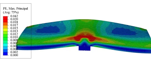
ambient temperature studies of punching shear [28]. Figure 16 shows a contour plot of the 11
principal stresses in the slab at the end of heating to show the effectiveness of this approach –the 12
classic cone shape failure shape of a punching failure is clearly visible. 13
[image:11.595.153.409.251.354.2]14
Figure 16 cracking pattern for the slab. 15
Figure 18 shows the maximum principal stresses through the thickness of the slab for the slow-16
fire scenario considered along a line at 45 degrees to the horizontal as shown in Figure 16. This 17
line approximates the (varying and non-linear) precise location of the maximum stresses, in line 18
with theories predicting crack formation, such as Mutoni’s Critical Shear Crack Theory [29]. 19
Accordingly, the maximum principal stresses are also approximately normal to this line. Stresses 20
at two states are plotted: at a lower surface slab temperature of 500 °C, and at incipient failure as 21
defined above. “Failure envelopes’’, which show the maximum tensile stress that the concrete can 22
sustain at each location, taking account of the temperature profiles and how concrete material 23
properties vary with temperature are also plotted. Figure 18a shows clearly the difference in 24
stresses that result from inclusion of LITS in the analysis, which in turn explain the differences in 25
deflections observed. By contrast Figure 18 b, indicates that at incipient failure, the stresses in the 26
slabs are very similar. This implies that LITS does not affect the failure mechanism of heated slabs 27
but that it does affect both stresses state before failure and the time (or temperature profiles) at 28
11 30
31
Figure 17 The assumed cracking path at failure. 32
[image:12.842.91.815.230.470.2](a) (b)
Figure 18 Stress state for the slab (a) when the bottom surface reaches 500 C° (b) at failure.
33
-5 -4 -3 -2 -1 0 1 2 3 4 5 6
0 10 20 30 40 50 60 70 80 90 100 110
M
a
x
im
um
princip
a
l
st
re
ss
,
M
P
a
Distance, mm Failure envelope
Stress profile for elevated temperature without LITS at 500 C°
Stress profile for elevated temperature with LITS at 500 C° -4 -3 -2 -1 0 1 2 3 4 5 6
0 10 20 30 40 50 60 70 80 90 100 110
M
a
x
im
um
princip
a
l
st
re
ss
,
M
P
a
Distance, mm
Failure envelope for ambient temperature model Failure profile for ambient temperature
Failure envelope for the model without LITS
Failure profile for elevated temperature without LITS Failure envelope for the model with LITS
12
8. Conclusions
34
Numerical studies have been presented that identify the role of LITS in the response of flat-slab 35
structures to fire. The results clearly show that LITS accounts for the apparently anomalous 36
experimental deflection results seen in punching shear experiments in the fire. While LITS has 37
been known of for a long time, in building structures its effects have often been assumed to be 38
small, and often ignored or included crudely in analyses. The results of this paper show that in 39
cases where compressive regions (herein slab soffits close to columns) govern structural 40
behaviour, this assumption is not valid. If LITS is not included in analyses, this will not only 41
result in incorrect deflection predictions but may also lead to non-conservative estimates of fire 42
resistance times. 43
The consequences of these findings for the design of slabs in punching shear in a fire should be 44
determined. In particular, the implications of the predictions for the recently developed and 45
widely adopted critical shear crack theory for flat slab design [29] should be identified. This 46
approach to calculating punching shear strength relies on estimates of the rotation of slabs to 47
predict initiation of cracking. The larger deflections (and hence rotations) seen experimentally in 48
fire conditions and now explained numerically, may mean the method needs additional calibration 49
for fire loading. For example, the currently available method of applying critical shear crack 50
theory in fire as developed by Bamonte [30], where the thermal displacement is added to the total 51
rotation of the slab, will likely need adjustment in order to account for LITS_induced rotations. 52
Further experimental and numerical studies should be undertaken to identify the likely effects of 53
LITS on stresses when in-plane restraint is present, as is likely in real floor plates. Compressive 54
in-plane stresses serve to increase punching shear capacity, and a simple analysis would suggest 55
restrained thermal expansion produces highly compressive in-plane stresses. However, if, as 56
appears likely, LITS results in lower compressive (or even tensile) in-plane stresses in fire, this 57
would result in punching shear capacity below that anticipated by current design approaches. 58
9. ACKNOWLEDGEMENTS
59
The authors acknowledge the support of The Higher Committee for Education and Development 60
in Iraq (HCED) for the financial support that made this work possible. 61
10.REFERENCES
62
[1] M. Ghoreishi, A. Bagchi, M.A. Sultan, Review of the Punching Shear Behavior of Concrete Flat Slabs in 63
Ambient and Elevated Temperature, Structural Fire Engineering. 4 (2013) 259–280. 64
[2] H. Salem, H. Issa, H. Gheith, A. Farahat, Punching shear strength of reinforced concrete flat slabs subjected 65
to fire on their tension sides, HBRC Journal. 8 (2012) 36–46. 66
[3] J.-S. Liao, F.-P. Cheng, C.-C. Chen, Fire Resistance of Concrete Slabs in Punching Shear, Journal of 67
Structural Engineering. 140 (2014) 4013025. doi:10.1061/(ASCE)ST.1943-541X.0000809. 68
[4] H.K.M. Smith, T. Stratford, L. Bisby, Deflection Response of Reinforced Concrete Slabs Tested in Punching 69
Shear in Fire, in: Applicatons of Structural Fire Engineering, Dubrovnik, Croatia, 2015. 70
[5] H.K.M. Smith, T.J. Stratford, L.A. Bisby, Punching Shear of Reinforced Concrete Slabs under Fire 71
Conditions: Experiment vs. Design, in: CONFAB 2015 Conference Proceedings, ASRANet Ltd, Glasgow , 72
United Kingdom, 2015. 73
[6] H.K.M. Smith, T. Stratford, L. Bisby, The Punching Shear Mechanism in Reinforced-Concrete Slabs under 74
Fire Conditions, in: East Langsing, Michigan, 2015: p. PROTECT conference. doi:10.1126/science.1247727. 75
[7] H.K.M. Smith, Punching Shear of Flat Reinforced-Concrete Slabs Under Fire Conditions, The University of 76
Edinburgh, 2016. 77
[8] K. Kordina, Über das Brandverhalten punktgestützter Stahlbetonplatten, Braunschweig, Oktober, 1993. 78
[9] K. Kordina, Über das Brandverhalten punktgestützter Stahlbetonplatten (On the Fire Behaviour of Reinforced 79
Concrete Flat Slabs), Deutscher Ausschuss für Stahlbeton (DAfStb), Berlin (Germany), 1997. 80
[10] A. Law, M. Gillie, P. Pankaj, Incorporation of Load Induced Termal Strain in Finite Element Models, 81
Application of Structural Fire Engineering. 49 (2009) 19–20. 82
13
the-art review, Engineering Structures. 127 (2016) 172–188. doi:10.1016/j.engstruct.2016.08.021. 84
[12] U. Schneider, Concrete at high temperatures - A general review, Fire Safety Journal. 13 (1988) 55–68. 85
doi:10.1016/0379-7112(88)90033-1. 86
[13] A. Law, The Assessment and Response of Concrete Structures Subjected to Fire, The University of 87
Edinburgh, 2010. 88
[14] Y. Anderberg, S. Thelandersson, Stress and deformation characteristics of concrete at high temperature: 2. 89
Experimental investigation and material behaviour model., Bulletin No. 46. (1976) 86. 90
[15] R.K. Salman, Behavior of Flat Plates under Eccentric Loading Using Shearhead Reinforcement, Al 91
Mustansiriya University, 2012. 92
[16] R.K.S. Al Hamd, M. Gillie, Y. Wang, M.M. Rasheed, Punching Shear – Eccentric Load and Fire Conditions, 93
in: CONFAB 2015 Conference Proceedings, ASRANet Ltd, Glasgow , United Kingdom, 2015: pp. 201–209. 94
[17] R.K. Salman, M.M. Rasheed, J.S.A. Al-Amier, A.M. Jamal Saeed Abd Al-Amier Asst Mohammed Rasheed, 95
R. Khdier Salman, Effect of Steel Shearhead on Behaviour of Eccentrically Loaded Reinforced Concrete Flat 96
Plate, Journal of Engineering and Development. 17 (2013) 14–27. 97
[18] W. Gao, J.G.T. Teng, J.G. Dai, Fire resistance of RC beams under design fire exposure, Magazine of Concrete 98
Research. 69 (2017). 99
[19] J. Lubliner, J. Oliver, S. Oller, E. Onate, A Plastic-Damage Model for Concrete, International Journal of 100
Solids and Structures. 25 (1989) 299–326. 101
[20] J. Lee, G.L. Fenves, Plastic-Damage Model for Cyclic Loading of Concrete Structures, Journal of 102
Engineering Mechanics. 124 (1998) 892–900. 103
[21] P. Grassl, M. Jirásek, Damage-Plastic Model for Concrete Failure, International Journal of Solids and 104
Structures. 43 (2006) 7166–7196. 105
[22] T. Jankowiak, T. Lodygowski, Identification of parameters of concrete damage plasticity constitutive model, 106
Foundations of Civil and Environmental …. (2005) 53–69. 107
http://www.ikb.poznan.pl/fcee/2005.06/full/fcee_2005-06_053-108
069_identification_of_parameters_of_concrete.pdf. 109
[23] R. Al Hamd, M. Gillie, Y. Wang, Finite Element Modelling of Concrete Slab-Column Connections Under 110
Eccentric Loads, (n.d.) 1. 111
[24] Eurocode 2, Eurocode 2: Design of concrete structures - Part 1-2: General rules - Structural fire design, 3 112
(2004). 113
[25] M. Gillie, A. Usmani, M. Rotter, M. O’Connor, Modelling of heated composite floor slabs with reference to 114
the Cardington experiments, Fire Safety Journal. 36 (2001) 745–767. doi:10.1016/S0379-7112(01)00038-8. 115
[26] R. Jansson, D. Lange, The fire behaviour of an inner lining for tunnels, 2015. 116
[27] D. Lange, R. Jansson, A comparison of an explicit and an implicit transient strain formulation for concrete in 117
fire, Fire Safety Science. 11 (2014) 572–583. doi:10.3801/IAFSS.FSS.11-572. 118
[28] A.S. Genikomsou, M.A. Polak, Finite Element Analysis of Punching Shear of Concrete Slabs Using 119
Damaged Plasticity Model in ABAQUS, Engineering Structures. 98 (2015) 38–48. 120
http://linkinghub.elsevier.com/retrieve/pii/S0141029615002643 (accessed May 26, 2015). 121
[29] A. Muttoni, Punching Shear Strength of Reinforced Concrete Slabs, ACI Structral Journal. 105 (2008) 440– 122
450. 123
[30] P. Bamonte, M.F. Ruiz, A. Muttoni, Punching Shear Strength of RC Slabs Subjected to Fire, in: 7th 124
International Conference on Structures in Fire, Zurich, Switzerland, 2012: pp. 689–698. 125


![Figure 7 Load-deflection behaviour of Salman’s experimental results [23] and that predicted by numerical simulations](https://thumb-us.123doks.com/thumbv2/123dok_us/9427506.447350/6.595.183.386.52.196/figure-deflection-behaviour-salman-experimental-predicted-numerical-simulations.webp)


![Bis[4 (dimethylamino)pyridinium] tetrabromidobis(3,4 dichlorophenyl)stannate(IV)–1 bromo 3,4 dichlorobenzene (1/1)](data:image/gif;base64,R0lGODlhAQABAIAAAP///wAAACH5BAEAAAAALAAAAAABAAEAAAICRAEAOw==)