© 2019, IRJET | Impact Factor value: 7.211 | ISO 9001:2008 Certified Journal
| Page 5064
SEISMIC BEHAVIOUR OF TAPERED BEAM COLUMN JOINT WITH
REDUCED BEAM SECTION
Adila Sathar
1, Rasim Navas
21
Mtech Student, Computer Aided Structural Engineering, ICET, Mulavoor P.O,
Muvattupuzha, Kerala, India
2
Assistant Professor, Civil Department, ICET, Mulavoor P.O, Muvattupuzha, Kerala, India
---***---Abstract -
Non-prismatic beam should mean beams withdifferent cross section along their longitudinal axis. Steel structural elements with variable cross-section, made of welded plates, are largely used in the construction industry. The RBS appears to be the most economical of the new design methods and is already being used by structural engineers for welded SMRF structures in seismic zones. This paper presents an analytical study on steel beam column joint with circular RBS and tapered web beam. Different taper ratios selected are 1.25, 1.5, and 1, to examine the load carrying capacity and column stress. Non-Linear dynamic analysis is conducted in ANSYS workbench 16.1 to observe the cyclic behaviour of web tapered beam with circular RBS. Ultimate load and displacement with corresponding time is observed for comparison. To achieve the nonlinear behaviour of models, dynamic analysis are used by FEM.
Key Words
:
Non-prismatic beams, Tapered beams,
Reduced beam section, cyclic behaviour, dynamic analysis.
1. INTRODUCTION
1.1 General Background
During a severe earthquake, the main structural elements like beams and columns are seriously affected. When a building is subjected to seismic wave, large amount of energy is distributed within in the building and the level of damage sustained by the building depends on the dissipation of this energy. Therefore a great concern is to be given for earthquake resisting systems to dissipate energy effectively from the structure. The primary function of an energy dissipation element is to reduce the damage in main structural components.
Steel structural elements with variable cross-section, made of welded plates, are largely used in the construction industry for both beams and columns in accordance with the stress and stiffness demand in the structure. These types of elements are mainly used for the design of single storey frames with pitched roof rafters and pinned column base. Rafters and columns can be designed as tapered members made of steel welded plates, respecting
the bending moment diagrams for gravitational load combination.
Reduced beam section (RBS) is one of the connection types, which is economical and popular for use in steel moment frames in seismic regions. By cutting some portions of the beam flanges near the column face, the RBS connections are designed to form plastic hinge within the RBS zone so that it could enhance the structural seismic performance.
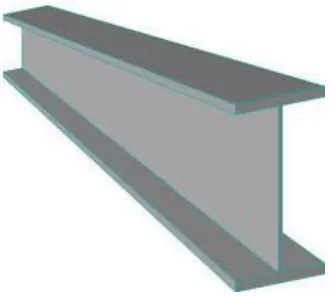
Fig -1: Tapered beam
2. NUMERICAL INVESTIGATION USING ANSYS
WORKBENCH 16.1
2.1 Base Model
[image:1.595.357.523.355.503.2]© 2019, IRJET | Impact Factor value: 7.211 | ISO 9001:2008 Certified Journal
| Page 5065
Table -1: Material Properties of Steel.
MEMBER COUPON LOCATIO
N
YIELD STRENGTH
(N/mm2)
TENSILE STRENGTH
(N/mm2)
Link beam Beam
flange 387 507
Beam web 429 527
Stub beam Beam
flange 371 511
Beam web 373 494
column Web and
[image:2.595.337.528.98.239.2]flange 431 578
Fig -2: Typical geometry details of RBS.
Table -2: Geometry details of circular RBS.
Distance of RBS from column face (a) 0.6 bf
Length of RBS (b) 0.75 bd
Depth of RBS (c) 0.25 bf
[image:2.595.40.283.115.444.2]
Table -3: Dimensions of web tapering.
SPECIFICATION MODEL
NAME TAPER RATIO WEB (mm) DEPTH OF
Weight constant (WC)
WC CRBS
TR 1.5 1.5 840/560
WC CRBS
TR 1.25 125 780/624
Section constant (SC)
SC CRBS TR
1.5 1.5 700/467
SC CRBS TR
[image:2.595.342.526.274.408.2]1.25 1.25 700/560
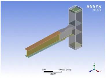
Fig -3: Modelled view of WC beam with TR 1.25.
Fig -4: Modelled view of SC beam with TR 1.5.
Circular RBS is found to be best among several configuration. The implementation of RBS reduces the column stress. So we introduce the circular reduced beam section to tapered beam. Analysis done by keeping the weight of beam (WC) constant and second by keeping the depth of web constant(SC).A cyclic predetermined loading sequence with increased displacement amplitudes specified in the AISC seismic provisions was used during the tests. The test history began with six cycles of ±0.375, ±0.5, and ±0.75% rad story drift angle. Subsequently, four cycles of ±1% rad story drift angle and two cycles with amplitudes of over ±1.5% rad story drift angle were applied.
.
[image:2.595.34.552.584.798.2]© 2019, IRJET | Impact Factor value: 7.211 | ISO 9001:2008 Certified Journal
| Page 5066
3. RESULTS AND DISCUSSIONS
3.1 Hysteretic behavior
[image:3.595.332.541.111.251.2]The analytical load-displacement hysteresis curves for the specimens are given below. It is observed that all the specimens shows stable hysteresis curves. Weight constant tapered beam with taper ratio 1.5 with circular RBS shows higher load carrying capacity and less column stress compared to other models.
[image:3.595.63.265.240.377.2]Fig -6: Hysteresis curve for WC CRBS TR 1.25.
Fig -7: Hysteresis curve for WC CRBS TR 1.5.
[image:3.595.331.540.292.422.2]Fig -8: Hysteresis curve for SC CRBS TR 1.25.
Fig -9: Hysteresis curve for SC CRBS TR 1.25.
Fig -10: Hysteresis curve for PB CRBS TR 1.
Fig -11: location of plastic hinge.
3.2 Load Deflection Analysis
[image:3.595.61.264.420.550.2] [image:3.595.340.527.451.615.2] [image:3.595.54.270.589.725.2]© 2019, IRJET | Impact Factor value: 7.211 | ISO 9001:2008 Certified Journal
| Page 5067
Fig -12: Load vs. deflection graph of different models.
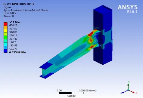
Fig -13: Equivalent von-mises stress for WC CRBS TR 1.5.
[image:4.595.39.281.94.273.2]Fig -14:Total deformation for WC CRBS TR 1.5.
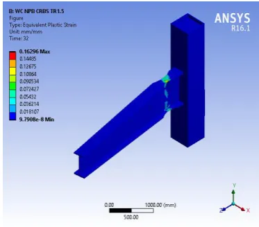
Fig -15:location of plastic hinge formation in WC CRBS TR 1.5.
[image:4.595.42.280.298.461.2]Table representing maximum load and column stress of various models were illustrated below.
Table -4: Maximum load and column stress of different models
MODEL NAME LOAD (kN) COLUMN STRESS
(N/mm2)
WC CRBS TR 1.5 603.17 169.59
WC CRBS TR 1.25 589.46 166.36
SC CRBS TR 1.5 702.29 156.27
SC CRBS TR 1.25 764.24 163.84
PB CRBS TR 1 622.14 175.5
4. CONCLUSIONS
This study proposed a new configuration of different RBS and their application in tapered beam column joint, the conducted analytical study on beam column joint result in following conclusions:
Section constant tapered beam with CRBS shows decrease in load carrying capacity as compared to prismatic beam with CRBS.
But weight constant tapered beam with CRBS shows increase in load carrying capacity.
WC CRBS TP 1.5 exhibited best result showing an increase in load carrying capacity of 22.84%.
By the effect of RBS and tapering column stress will be also reduced.
[image:4.595.304.565.343.472.2]© 2019, IRJET | Impact Factor value: 7.211 | ISO 9001:2008 Certified Journal
| Page 5068
ACKNOWLEDGEMENT
I wish to thank the Management, Principal and Head of Civil Engineering Department of Ilahia College of Engineering and Technology, affiliated by Kerala Technological University for their support. This paper is based on the work carried out by me (Adila Sathar), as part of my PG course, under the guidance of Mr. Rasim Navas (Assistant Professor, Ilahia College of Engineering and Technology, Muvattupuzha, Kerala). I express my gratitude towards her for her valuable guidance.
REFERENCES
[1] Cheng-Chih Chen , Chun-Chou Lin “Seismic performance
of steel beam-to-column moment connections with tapered beam flanges” ,2016.
[2] N.S. Trahair , “Bending and buckling of tapered steel
beam structures” ,2014.
[3] Yuan W-B, Kim B, Chen C-Y. “Lateral-torsional buckling
of steel web tapered tee-section cantilevers”. J Constr Steel Res 2013;87:31–7.
[4] P. Hradil, M. Mielonen, and L. Fülöp, "Optimization tools
for steel portal frames – Optimization results", Research report VTT-R-00567-11,2011.
[5] N.S. Trahair , P. Ansourian , “In-plane behaviour of
web-tapered beams”. 2015
[6] Trahair NS, Ansourian P. “In-plane behaviour of
web-tapered beams. Eng Structures” 2016;108:47–52.
[7] Wang ZS, Su MZ, Song AL, Pang Z, Shen L. “A seismic test
and finite element analysis of light-weight steel portal frame with tapered members.” Adv Mater Res 2012;368:211–4.
[8] S. Wilkinson et al,” A moment resisting connection for
earthquake resistant structures “Journal of Constructional Steel Research 62 (2006) 295–302
[9] Iwankiw, N,(2004), “Seismic design enhancement and