Replication and Fabrication of Crafted and Natural
Artifacts by Reverse Engineering using
Single Camera Photogrammetry
John Kaufman
A Thesis Submitted for the Degree of PhD
Lancaster University
II Disclaimer
I hereby declare that this submission is my own work and it contains no material previously published or written by another person, to the best of my knowledge and belief, nor material which has been accepted for the award of any other degree or diploma of the University or other institute of higher learning except where due acknowledgements have been made in the text.
This thesis is submitted in partial fulfilment of the requirements for the degree of Doctor of Philosophy
Author: ……… J Kaufman
III Acknowledgements
The author of this thesis would like to thank the following individuals and organisations for supporting this research activity:
Dr Allan Rennie for his supervision and guidance throughout the period of time I have been studying at Lancaster University as an off campus student. All members of the Lancaster Product Development Unit are thanked for their guidance and for providing many of the fabricated models. I would also like to thank the members of the University Study Skills Unit who provided the author with help and guidance when requested.
This research would not have been possible without the use of the computer software supplied for the duration of the research by Agisoft’s PhotoScan Pro®, Netfabb’s Studio Pro5®
andAutoDesSys’ form-Z pro®, for which I am very grateful. Thanks also to Mcor Technologies for the fabrication of two models, the Eureka Cat and Eureka Man, using their Iris® Colour printer and to 3D Systems for the fabrication on their ProJet 660® of the Clay Head, Egyptian Bowl and Sobekhotep models.
Thanks is also given to the staff at Kendal Museum, Kendal, Cumbria for their help and collaboration, use of their Egyptian artifacts, and workshop space during the data collection phase.
IV
Abstract
Photogrammetry has been used for recording objects for well over one hundred and fifty years. Modern photogrammetry, or digital image capture, can be used with the aid of a single medium range Digital Single Lens Reflex (DSLR) camera, to transform two-dimensional (2D) images into three-dimensional (3D) Computer Aided Design (CAD) spatial representations, and together with the use of additive manufacturing (AM) or 3D Printing technology, geometric representations of original cultural, historic and geological artifacts can be fabricated using a process known as Non-invasive Reverse Engineering. Being able to replicate such objects is of great benefit to educationalists and, for example, curators; if the original object cannot be handled because it is fragile, then replicas can give the handler a chance to experience the size, texture and weight of rare objects. Photogrammetry equipment is discussed, the objective being simplicity of execution for eventual realisation of physical products such as the artifacts discussed in this thesis. All the digital photographic data in the research has been captured either with the use of a mid-range DSLR camera or a compact “point and shoot” camera. As the processing power of computers has increased and become more widely available, and with the use of user-friendly software programs it is now possible to digitally combine multi-view photographs, taken from 360° around the object, into 3D CAD representational virtual images, transforming these so they are ready for AM machines to produce replicated models of the originals.
Over 50 objects were used in this research and the results documented: from the reproduction of small modern clay sculptures; 3,500-year-old Egyptian artifacts; household vases, figurines and bottles; fossils, shells and rocks, although not all successfully recreated. A variety of AM technologies have been employed, mostly monochromatic but including colour AM machines, to fabricate the models where good 3D models have been obtained.
V
VI
Table of Contents
Disclaimer II
Acknowledgements III
Abstract IV
Table of Contents VI
List of Figures XIV
List of Tables XXV
List of Abbreviations and Acronyms XXVII
Appendices Contents see separate booklet XXX
Outputs XXXII
Contribution to Knowledge XXXIII
Chapter 1: Introduction and Background History 1
1.1 Introduction 1
1.2 Overview 1
1.3 Research Objectives 1
1.4 Digital Image Capture 3
1.5 Software programs 3
1.6 Headings and Contents for Main Body of Thesis 4
1.7 Introduction to Background History 6
1.8 Aristotle and Euclid 7
1.9 Camera Obscura 7
1.10 The Next 500 Years 9
1.11 Capturing the Photographic Image – the Early Pioneers 10
1.12 Photographic Cameras 11
1.12.1 Stereoscopic Images 11
1.12.2 Photogrammetry 15
VII
1.12.4 Le Corbusier 15
1.12.5 Spy in the Sky 17
1.13 Birth of Digital Cameras 17
1.14 The Ruby Red Beam 18
1.15 Laser Scanners 18
1.16 Personal Computers 19
1.17 Development of LS and CAD 19
1.18 Cost of Laser Scanners 22
1.19 Virtual 3D Representational Images 26
1.20 3D Reliefs 27
1.20.1 Bas-relief, Sunken and Raised Relief 27
1.20.2 Image-Based Displacement 29
1.21 Historical Conclusion 30
Chapter 2: Literature Review and Research Objectives 32
2.1 Introduction to Photogrammetry 32
2.2 Overview 33
2.3 Medical 33
2.4 Archaeology 36
2.5 Museums 38
2.6 Cultural Heritage 40
2.7 Aerial Surveillance 44
2.8 Archiving and Storage of Data 45
2.9 Heritage Lost and Gained 46
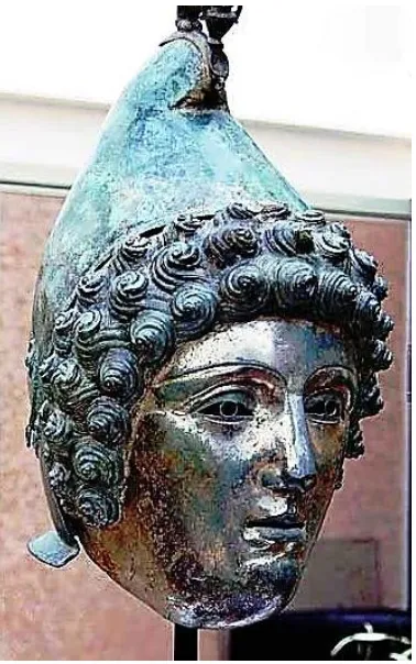
2.9.1 The Crosby Garrett Helmet 46
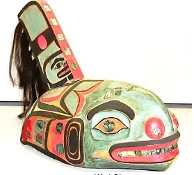
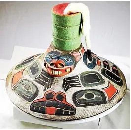
2.9.2 Tlingit Community of southeast Alaska, USA 50 2.10 Research Objectives - Development of Simpler
Data Capture & Processing 51
2.11 Technology for Computer-literate Operatives 52 2.12 A Cost Effective, Cheaper and Safer System 53
2.13 Systems Utilisation 54
2.13.1 Local Community projects 54
2.13.2 Educational institutions 55
VIII
2.13.4 Non-invasive Replication of Unique Objects 59
2.14 Product Promotion for Business 59
2.15 Spatial/Tactile Experience by Blind and Visually Impaired 61
2.16
Conclusions 64
2.16.1 Literature Summary and Gaps in Knowledge 64 Chapter 3: Tools of the Trade – Hardware and Software 66
3.1 Photographic Hardware 66
3.2 The Camera 66
3.3 The Lens 67
3.3.1 Close-up Lens 67
3.3.2 Neutral Density Lens 69
3.4 Additional Camera Equipment 70
3.4.1 Compact Camera Support Frame 71
3.4.2 Turntable and other Props 72
3.5 Compact Camera Test – Canon IXUS 100IS® 74
3.6 Lighting 75
3.6.1 Lighting and the Kelvin Scale 76
3.6.2 Basic Lighting Equipment 78
3.7 White Balance and Grey Scale 79
3.7.1 Accuracy of the Colour requirement 80
3.7.2 Consistency in Colour printing 81
3.7.3 Uniformity of AM printers and inks 82 3.7.4 Auto White Balance camera mode 84
3.8 Light Tents 87
3.8.1 Light Tent Construction 87
3.8.2 “Studio” Lighting Conditions – Spain 89
3.9 Open Room Studio 90
3.10 Alternative “Open Studios” 92
3.11 Software 95
3.11.1 AutoDesk - 123 Catch® 95
3.11.2 Agisoft – PhotoScan Pro4® 96
IX
3.11.4 DeskArts 3Data Expert® 98
3.11.5 Dassault Systèmes - SolidWorks® 99
3.12 Software Summary 100
Chapter 4: Methodology for 3D Reconstruction 101
4.1 Method 1 101
4.1.1 Open Room Studio – Setting the Scene 101
4.1.2 Data Capture – 123D Catch® 103
4.1.3 Computer Data Primary Processing 106
4.2 Case Studies 107
4.2.1 Clay Head 107
4.2.2 Unglazed Ceramic Vase 111
4.2.3 China Figurine Serenity 113
4.3 Data Chart and Image library 116
4.4 Creation of 3D Video 117
4.5 Summary 120
4.6 Method 2 120
4.6.1 “Light Tent” technique 120
4.6.2 Standard Data Capture – using PhotoScan Pro4® 122
4.7 Depth of field 123
4.8 Lens Diffraction 126
4.8.1 Histograms 130
4.9 Software control – semi automatic 132
4.10 Pre-Process Masking 134
4.10.1 Alternative uses for Pre-Process Masking 136 4.10.2 Digital Photographs, Point Cloud and 142
Polygon Images
4.11 High and Low Resolution Images 147
4.11.2 Print Problems Associated with 149 High Resolution Data 4.12 Bench Marking the Model and Adapting to the Limitations 152 of AM Technology
X
4.13 AM Printer Software 164
4.13.1 AM Printer Drivers 170
4.14 Digital Photographic Information held with the Image 171
4.14.1 Focusing onto the Target 172
4.15 Data Chart and Image Library – with PhotoScan Pro4® 176 4.16 Method 3 - Adapting to Working Environments 177
4.16.1 Using a Backcloth on its Own 177
4.16.2 Hanging on the Wall 181
4.17 Coded and Non-Coded targets 182
4.18 Summary Methodology 2 & 3 185
Chapter 5: Secondary Processing 187
5.1 Using netfabbPro5® 187
5.2 Reorientation 190
5.3 Measuring the Digital Image 193
5.4 Scaling and Resizing 196
5.4.1 Scaling using PhotoScan Pro4® 197
5.4.2 Scaling using 123D Catch® 197
5.4.3 Scaling using netfabbPro5® 198
5.5 Slicing or Free Cutting 202
5.6 Hollowing 204
5.6.1 Shell creation 204
5.6.2 Volume of Material used dictated by Shell 206 Thickness or Artifact attributes
5.6.3 Observations on Material Utilisation as used 211 in the Replication of the Artifacts
5.7 Boolean Operation 212
5.8 Other useful features 213
5.9 Summary 216
Chapter 6: Repair, reconstruction and construction 218 6.1 Returned Noisy data Distorted and Incomplete Data 218
6.1.1 Returned Noisy data 218
6.1.2 Incomplete data. 219
XI
6.1.4 Repair using the Mesh 223
6.2 Damaged Digital Images Beyond Repair 225
6.2.1 Figure K.01 - Serenity – Items G.03 and H.32 227 6.2.2 Figure K.02 – Dolphins – Items G.04 and H.33 229 6.2.3 Figure K.03 – Glazed Vase – Item G.06 229 6.2.4 Figure K.04 – Mollusc - Item G.08 229 6.2.5 Figure K.05 – Frosted Bottle - Items G.10 and H.32 231 6.2.6 Figure K.06 – Ceramic Vase - Item G.15 232 6.2.7 Figure K.07 – China Dish - Item H.37 232 6.2.8 Figure K.08 – Batwing Sea Shell - Item H.50 232 6.2.9 Figure K.09 - Lincrusta – Acanthus - Item – G.16 233 Figure K.10 - Lincrusta – Aphrodite - Item – G.17 233
6.3 Summary of Repaired Data Images 235
6.4 Removing Flare/Glare and Reflection 236
6.4.1 Polarising filters 236
6.4.2 Testing CPL Filters – Artificial Lighting 238 6.4.2 Testing CPL Filters – Natural Lighting 240
6.5. Digital Negative Editing Software 242
6.5.1 File Format 242
6.5.2 Editing the Data, Post-processing 244
6.6 Overview of other uses and benefits 245
6.7 Repair of broken Photographic Frame 246
6.7.1 The Stair Stepping effect 251
6.8 The Egyptian Bowl 251
6.9 The lost Crown of Horus 254
6.10 Educational use 259
6.10.1 Further use of Horus’s Crown 261
6.10.2 Morphing Models 262
6.10.3 A stand for the Amphora 265
6.10.4 Flat Bottom Grain Jar 267
6.10.5 Making Technical Drawings of the Models 267
XII
Chapter 7: Compact Camera v DSLR 271 7.1 Compact camera as an alternate option 271
7.2 Basic Trail 272
7.3 The Griffin 275
7.4 Summary 279
Chapter 8: The Finished AM Replicated Models 281
8.1 Introduction to the AM models 281
8.2 Current Diversity 281
8.3 General Observations on Replicated Artifacts 284
8.3.1 Defect or Enhancement 285
8.4 Colour Printing 288
8.4.1 Eureka Cat and Man 288
8.4.2 ‘Greyed out’ 294
8.5 Monochrome Models 295
8.5.1 Clay Head 295
8.6 The Egyptians - Ancient 297
8.6.1 Sobekhotep 297
8.6.2 The Bowl 299
8.6.3 The Vase 301
8.7 The Egyptians – Modern 304
8.7.1 Painted Fish Vase 304
8.7.2 Horus 305
8.8 The Dog 307
8.9 The Warrior 310
8.10 Ceramic Vessels 311
8.11 Handled Vessels 314
8.12 Concrete Mix 316
8.13 Items from the Natural World 317
8.13.1 Sea Shell 318
8.13.2 Fossils – Ammonite 319
8.13.3 Fossils – Trilobite 320
XIII
8.15 Summary 323
Chapter 9: RAW digital negatives 324
9.1 Historical Background 324
9.2 The Search for Solutions 325
9.3 The Digital Negative 326
9.4 Tiff and Jpeg 326
9.5 Size Matters 327
9.6 Case Studies 328
9.6.1. Warrior 330
9.6.2. Serenity 331
9.6.3. Dolphins 332
9.6.4. China Dish 333
9.7 RAW v Jpeg - For and Against 335
9.8 Conclusion 337
Chapter 10: Conclusion and Future Research 339
10.1 Introduction 339
10.2 Core Research Questions 340
10.3 Methodological Reconstructions 341
10.4 Empirical Findings 346
10.5 Theoretical Implications in RE using SC Photogrammetry 348 10.6 Limitation of the Study and Challenges 349
10.7 Recommendations for Further Research 351
10.7.2 Colour Fabrication 352
10.7.3 Questionnaires 352
10.8 Conclusion 354
XIV List of Figures
Chapter 1: Introduction and Background History Page
Figure 1.1 Sequential animation of goat leaping into the air to feed from plant 6 Figure 1.2 Frisius Gemma ’s illustration “ Eclipse of the Sun 24th January, 1544” 8 Figure 1.3 Johann Zahn, camera obscura portabilis, 1685. 8 Figure 1.4 Fox Talbot’s first captured photographic negative image 10 Figure 1.5 Hare’s Stereoscopic camera – c1857 12 Figure 1.6 Lenticular’s Stereoscope - c1860 12 Figure 1.7 Typical double image for binocular vision 13 Figure 1.8 Kilbourne Stereo Daguerreotype in folding stereoscope – c1860 13 Figure 1.9 Zeiss pocket stereoscopic viewer 14 Figure 1.10 Panasonic State of the art still/ video camera 14 Figure 1.11 Drone or UAV as bought in the local electronics shop with camera 16 Figure 1.12 c1975 Sasson’s Digital camera 17 Figure 1.13 Point Cloud 2D enlargement of head section – Front view 20 Figure 1.14 Enlarged head section – side view. 20 Figure 1.15 Full image – 67,063 points 21 Figure 1.16 3D scanned survey of Byland Abbey, North Yorkshire 22 Figure 1.17 Trimble MX2 Dual Head digital laser scanner 23 Figure 1.18 DAVID Structured Light Scanner SLA-2 3D-Scanner® 24 Figure 1.19 DIY 3D scanner camera Kit 24 Figure 1.20 Examples of 3D virtual textured point cloud data images 26 Figure 1.21 Roman pot shard – bas-Relief 27 Figure 1.22 Egyptian Horus raised-relief 28 Figure 1.23 Full rendered Computer Relief 29 Figure 1.24 Top and Bottom of Block showing surface displacement according
to grey scale colour intensity 30
Chapter 2: Literature Review and Research Objectives
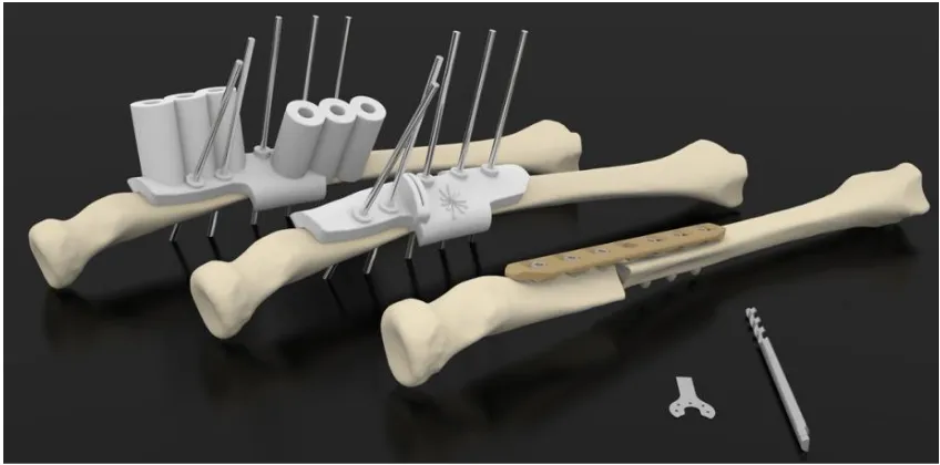
Figure 2.1 X-ray showing deformed arm bone 34 Figure 2.2 Drilling guide for fixing plate attached to model of bone 35 Figure 2.3 POIGO - Bridging the gap between Surgeon and Engineer 36 Figure 2.4 Bronze Copper helmet and mask 47 Figure 2.5 Children look eyeball to eyeball with their cultural history 48
Figure 2.6 Pre cleaned Helmet 48
Figure 2.7 After cleaning – as displayed at Christie’s 2010 49
Figure 2.8 The Kéet S’aaxw hat 50
XV
Figure 2.12 Entry Level Computer - MakerBot® 57 Figure 2.13 Children handling the Museum replicas 58 Figure 2.14 Children handling replicated models of 3500 year old Egyptian
artifacts 58
Figure 2.15 Contemporary Designed Bottle 58
Figure 2.16 Goveshy 60
Figure 2.17 Morling 60
Figure 2.18 Clay Head 61
Figure 2.19 Glazed Clay Bottle 61
Figure 2.20 Mona Lisa by Leonardo De Vinci 62 Figure 2.21 AM Bas-relief of Mona Lisa – shot from above 62 Figure 2.22 AM Bas-relief of Mona Lisa – shot just above horizontal plane 63 Figure 2.23 Original relief painting showing position of X section A/B 63 Figure 2.24 Horizontal cross section of STL virtual image 64
Chapter 3: Tools of the Trade – Hardware and Software
Figure 3.1 Nikon D3100® DSLR Camera 66 Figure 3.2 AF-S DX Zoom- Nikkor® 18-55mm f/3.5-5.6. - Zoom Lens 66 Figure 3.3 Typical set of Close up lenses 67 Figure 3.4 The Warrior – effect of - f/18 @ 35mm +0 68 Figure 3.5 The Warrior – effect of - f/18 @ 35mm +4 68 Figure 3.6 The Warrior – effect of - f/18 @ 40mm +10 68 Figure 3.7 Models shot at 140mm distance 69 Figure 3.8 Models shot at 140mm distance but with +10 dioptre lens 69 Figure 3.9 Selection of Neutral Density square and round Filter 70 Figure 3.10 Frame curvature as seen from above. 71 Figure 3.11 Curved pipe supporting 3 compact cameras 71 Figure 3.12 AM support arms and frame 71 Figure 3.13 Close-up of turn table showing degree markings. 72
Figure 3.14 Turn table as in use. 73
Figure 3.15 Use of cord to control radial distance. 73 Figure 3.16 Use of pole to control radial distance 74 Figure 3.17 Colour Temperature – the Kelvin Scale 77 Figure 3.18 bip® fluorescent floodlight 78 Figure 3.19 Single bulb 45W floodlight 78 Figure 3.20 A page from the Nikon Manual 79 Figure 3.21 Small part of the Pantone colour chart 81 Figure 3.22 BSi Fan Deck 475 colours 82
Figure 3.23 Original Photograph 85
Figure 3.24 Screen shot point cloud image 85
XVI
Figure 3.26 Stratasys PolyJetJ750® model v1 85 Figure 3.27 Original Sobekhotep model 86 Figure 3.28 Wrl file created in formZ 8 SE® 86 Figure 3.29 Model from PolyJet J750® 86 Figure 3.30 Re-printed colour model from the PolyJet J750® machine v2 87 Figure 3.31 Light tent set up in museum workshop – with poplin cover 88 Figure 3.32 Light tent set up without poplin cover but showing Chroma backdrop 88 Figure 3.33 Spanish walk-in-light tent 89 Figure 3.34 Under grey, dull, northern English, cloudy skies 90 Figure 3.35 Typical artifact – indicated - being photographed in Open Room setup
using florescent light 91
Figure 3.36 Light Tent under the florescent lighting, including ceiling downlights 91 Figure 3.37 Photogrammetry under a Spanish Naya. Backdrop hung on wall 92 Figure 3.38 Backdrop hung from wall but with lighting - Indoors in the UK 93 Figure 3.39 Photographed whilst still hanging on wall 94 Figure 3.40 Infinite-Realities multi camera studio 94
Figure 3.41 Amphora stand 99
Figure 3.42 Arm of compact camera frame 99 Figure 3.43 Final rendering of Horus’s Crown 99 Figure 3.44 Un-rendered version of Horus’s Crown 99
Chapter 4: Methodology for 3D Reconstruction
Figure 4.1 Data Capture - Advantageous camera angles 101 Figure 4.2 Data Capture – Supporting model above horizontal plane 102 Figure 4.3 Correlation between camera position and horizontal image deviation 102 Figure 4.4 Four frames from part of the Data set of 75 photographs 103 Figure 4.5 123D Catch® Data processing Flow chart 104 Figure 4.6 Close-up screen shot of virtual image waiting to be cleaned 105 Figure 4.7 Clay head identified in blown up image amongst background “noise” 105
Figure 4.8 Original Clay head 107
XVII
Figure 4.20 China figurine - Dark shadows and plumes 115 Figure 4.21 Vertical view of Video Map 118 Figure 4.22 Enlargement of Figure 4.21 showing camera position and projected
image of the tracking path produced by the software 118 Figure 4.23 Changes that can be made to video path. 119 Figure 4.24 Turn Table and Green Chroma Key backdrop 121 Figure 4.25 The Egyptian Vase on the turn table 122 Figure 4.26 Results of out of focus images on an SLS fabricated Bowl 123 Figure 4.27 SLS fabricated Bowl using PhotoScan Pro® 124 Figure 4.28 Bowl - Double point cloud image, caused by initial out of focus data 124 Figure 4.29 Bowl - A texture point cloud “Fur” infill created by computer 125 Figure 4.30 Egyptian Bowl - Stitching of images c/o Agisoft 125 Figure 4.31 Screen shot of completed textured point cloud Egyptian bowl 126 Figure 4.32 Contrasting sharpness between f/stop images 127/128 Figure 4.33 The “Quality” results of the scanned images 129 Figure 4.34 Enlarged images to show difference in sharpness 129/130 Figure 4.35 Histogram - PhotoShop CS6® 131 Figure 4.36 Histogram - PhotoShop Elements 11® 131 Figure 4.37 Nikon User Manual explanation of RGB Histogram 132 Figure 4.38 PhotoScan Pro® Data processing Flow Chart 133 Figure 4.39 Complex Masking line without Chroma Key backdrop 134 Figure 4.40 Simplified masking operation when backdrop is used. 134 Figure 4. 41 Non-masked images of the Egyptian Vase – pre-processing 135 Figure 4.42 Masked images of the Egyptian Vase – pre-processing 135 Figure 4.43 Original image – part of image data set of Concrete Mix 136 Figure 4.44 Original image - Sea Shell 137 Figure 4.45 Positive masked over sea shell support 137 Figure 4.46 Negitive mask of sea shell 137
Figure 4.47 Final Textured shell 137
XVIII
Figure 4.59 Three types of mesh – depending on the number of polygons created 147 Figure 4.60 Section of polygon mesh enlarged from Medium resolution image 149 Figure 4.61 Original Ammonite fossil 150
Figure 4.62 Hand painted replica 150
Figure 4.63 Ultra-High resolution Jpeg model 153 Figure 4.64 Ultra-High resolution Tiff model 153 Figure 4.65 High resolution - Jpeg model 153 Figure 4.66 High resolution - Tiff model 153 Figure 4.67 Original photograph of Warrior 153
Figure 4.68 CR Jpeg model 153
Figure 4.69 Original model size 25mm high 153 Figure 4.70 Fabricated model size 25mm high 153
Figure 4.71 Bench mark model heads 154
Figure 4.72 Medium resolution - Jpeg and Tiff models 155 Figure 4.73 Low resolution - Jpeg and Tiff models 155 Figure 4.74 Ultra Low resolution - Jpeg and Tiff models 155 Figure 4.75 Layout of models for printing on the PolyJet J750® 156 Figure 4.76 Top view of heads showing grain or layer direction 157 Figure 4.77 Screen shot of the manual build platform layout from GrabCAD® 164 Figure 4.78 Screen shot of the Automatic layout from GrabCAD® 165 Figure 4.79 Screen shot of the Automatic layout from GrabCAD® 165
Figure 4.80 Ultimaker 250µm model 166
Figure 4.81 Without supports 166
Figure 4.82 Model showing outside supports 166 Figure 4.83 Slice level 332 - showing information about the print structure of the model in “Custom” Mode. 168
Figure 4.84 Slice level 1187 169
Figure 4.85 Enlargement of filament layers 169 Figure 4.86 Extra Fine Profile - 0.25mm nozzle 169 Figure 4.87 Fine Profile - 0.4mm nozzle 169 Figure 4.88 Fine Profile - 0.6mm nozzle 170 Figure 4.89 Normal Profile - 0.8mm nozzle 170 Figure 4.90 G code from the instructions as downloaded into a word processor 171 Figure 4.91 Digital information relating to the photographic image. Colour channel
histograms shown separately 173
Figure 4.92 Digital information relating to the photographic image. Colour channel
histograms seen combined 174
Figure 4.93 Photographing the Trilobite under a Naya with only natural light 178
Figure 4.94 Original Rock 179
XIX
Figure 4.97 Original small rock 180
Figure 4.98 Textured dense cloud image of small rock with wood prop removed 181 Figure 4.99 Relief canvas - Camera positions as seen from above looking down 181 Figure 4.100 Relief canvas - Camera positions as seen from horizontal plane 182 Figure 4.101 Selection from the Photographic sequence from 68 images 182 Figure 4.102 Agisoft non coded targets 184
Figure 4.103 Coded targets 184
Figure 4.104 Quadra1 - underwater target frame 184 Figure 4.105 Selection of target shapes 185
Chapter 5: Secondary Processing
Figure 5.1 Main data processing functions of StudioPro® 188 Figure 5.2 Original imported image of Botijo 190 Figure 5.3 Reoriented image of Botijo 190 Figure 5.4 Botijo - Front facing - correct orientation 191 Figure 5.5 X,Y,Z Orientation of the three programs 192 Figure 5.6 Imported orientation into netfabbPro5® from PhotoScanPro4® 192 Figure 5.7 Orientation of imported part and rotation table for realignment 193 Figure 5.8 Measuring tools and essential dimensions displayed 195 Figure 5.9 Removal of bulge at bottom of model 196 Figure 5.10 Botijo - Direct Imported dimensions and orientation 198 Figure 5.11 Botijo - Reoriented to correct frontal view 199 Figure 5.12 Botijo - Incorrect ratio used – therefore dimensions are incorrect 200 Figure 5.13 Botijo - Correct ratio obtained from correct alignment of artifact 201 Figure 5.14 Screen shot of new multi-dimensional Automatic Scaling chart 202 Figure 5.15 “Free cutting” tool to slice off the stepped bottom of a Botijo jug. 203 Figure 5.16 Flattening the rounded bottom of the Botijo jug 203
Figure 5.17 Half Ammonite Shell 204
Figure 5.18 Point measurements of wall thickness of Ammonite 205
Figure 5.19 Smooth Hollowed Botijo 206
Figure 5.20 Measuring points of Botijo wall thickness 206 Figure 5.21 Volume of the solid figurine is displayed on chart 209 Figure 5.22 Boolean effect – light subtracted from dark 212 Figure 5.23 Down the drain hole and into the hollowed model 213 Figure 5.24a Netfabb model information report - Part Analysis 214 Figure 5.24b Netfabb model information report - Platform Views 215 Figure 5.25 Automatic mesh lines filling in the large hole of the Trilobite. 217
Chapter 6: Repair, reconstruction and construction
XX
Figure 6.2 Hole under chin – automatic mesh repair 219 Figure 6.3 Distortion on top of head 220 Figure 6.4 Red polygons ready to be removed 220 Figure 6.5 Hole in Vase mesh due to lack of digital data 221 Figure 6.6 Inner Vase mesh now complete 222 Figure 6.7 Identifying and Manually stitching/matching 3 points to integrate
additional digital images 223
Figure 6.8 Area needing to be cleaned at mouth of Egyptian Vase 224 Figure 6.9 Working with a large scale mesh – Egyptian Vase 224 Figure 6.10 Figurine – textured point cloud image - rough, spikey surface. 227 Figure 6.11 Figurine - High resolution point cloud image 228 Figure 6.12 Mollusc - High resolution point cloud image 230 Figure 6.13 Enlarged surface texture of original Mollusc – note ridge surface 231 Figure 6.14 Smooth Shell surface of original surface to orange peel
effect on image 232
Figure 6.15 Part of a roll of Lincrusta – Design “Acanthus” 234 Figure 6.16 Without CPL filter - Focal length 36mm @ f/11 @1/1.6s 237 Figure 6.17 With CPL filter - Focal length 36mm @ f/11 @ 1/1.3s 237 Figure 6.18 CPL filter not rotated - fl/48mm @ f/11 @ 2.5sec 234 Figure 6.19 CPL filter rotated - fl/48mm @ f/11 @ 3sec 238 Figure 6.20 No filter - fl/48mm @ f/11 @ 1sec 238 Figure 6.18a Enlarged image - CPL filter not rotated - fl/48mm @ f/11 @ 2.5sec -
artificial lighting 239
Figure 6.19a Enlarged image - CPL filter rotated - fl/48mm @ f/11 @ 3sec –
artificial lighting 239
Figure 6.20a Enlarged image - No filter - fl/48mm @ f/11 @ 1sec - artificial lighting 239 Figure 6.21 CPL filter not rotated - fl/48mm @ f/11 @ 2.5sec 240 Figure 6.22 CPL filter rotated - fl/48mm @ f/11 @ 3sec 240 Figure 6.23 No filter - fl/48mm @ f/11 @ 1sec 240 Figure 6.21a Enlarged image - CPL filter not rotated - fl/48mm @ f/11 @ 2.5sec 241 Figure 6.22a Enlarged image - CPL filter rotated - fl/48mm @ f/11 @ 3sec 241 Figure 6.23a Enlarged image - No filter - fl/48mm @ f/11 @ 1sec 241 Figure 6.24 Photo frame missing corner 246
Figure 6.25 Damaged corner removed 246
Figure 6.26 Digital image of frame 247
Figure 6.27 Frame Mask 247
Figure 6.28 Mirrored corner of frame 248 Figure 6.29 Small discrepancy on the frame to be rectified 249 Figure 6.30 Reverse of repaired frame 249
Figure 6.31 Repaired Frame 250
XXI
Figure 6.34 Underside of bowl 253
Figure 6.35 Inside of new bowl 253
Figure 6.36 Horus minus his crown 254
Figure 6.37 Point cloud image of Horus 254 Figure 6.38 Four styles of crown from large researched range 255 Figure 6.39 FDM printed model - version 1 – no support bar - unpainted 255 Figure 6.40 Crown being constructed within SolidWorks® 256 Figure 6.41 SolidWorks® screen shot - Crown version 2 257 Figure 6.42 3D printed model - Final version 2 – hand painted 257 Figure 6.43 SolidWorks® Screen shot – Horus and unattached crown 257 Figure 6.44 Finished unpainted SLS model of Horus 258 Figure 6.45 Hand painted finished model of Horus 258 Figure 6.46 The SL2 model of XYZRGB® structured light scanner 259 Figure 6.47 The first loft of the inner crown 261 Figure 6.48 Second outer crown added 261 Figure 6.49 Top Dome & fillet added to inner crown 261 Figure 6.50 Top of outer crown added and edges smoothed 261 Figure 6.51 Curled front swept extrusion added 262 Figure 6.52 Second support bar added 262 Figure 6.53 RepRap® machine as sold on e-Bay for £250.00 263
Figure 6.54 Original Roman jug 263
Figure 6.55 Screen shot of *.stl image 263 Figure 6.56 Screen shots of addition parts made for jug 264 Figure 6.57 The three stages of transformation 264
Figure 6.58 “Dressel” Wine amphora 265
Figure 6.59 Screen shot of amphora *.stl image 265 Figure 6.60 Greco Roman amphora and stand 266 Figure 6.61 SolidWorks® amphora stand 266 Figure 6.62 Unpainted white AM fabricated amphora and black stand 266
Figure 6.63 Modern flat bottom jar 267
Figure 6.64 Morphed jar together with original 267 Figure 6.65 2D Drawing of figurine Sobekhotep with information extracted from DeskArtes’
3data Expert® 268
Figure 6.66 Five parts of the Boxed Set Transporter 270
Chapter 7: Compact camera v DSLR
XXII
Figure 7.6 Dog – Resolution 640 x 480 274
Figure 7.7 The Griffin 275
Figure 7.8 Dense Cloud image of Griffin 275 Figure 7.9 Section from Shield – from 123D Catch® 276 Figure 7.10 Section from Shield – from PhotoScan® 276 Figure 7.11 Section from Shield – from original photograph 276 Figure 7.12 Original digital image and section used for comparison 276 Figure 7.13 Screen shot from netfabbPro5
®
. Imported from:- Left - 123D Catch®
Right - PhotoScan® 278 Figure 7.14 Detail from shield – 123D Catch® 279
Figure 7.15 Detail from shield – PhotoScan® 279
Chapter 8: The Finished AM Replicated Models
Figure 8.1 Gartner’s 3D Printing Hype Cycle 2015 282
Figure 8.2 Gartner’s 2017 Trends 283
Figure 8.3 Miniature FDM black dog – 50mm long x 20mm high
seen alongside original clay dog 285 Figure 8.4 Enlarged detail of miniature FDM dog 286 Figure 8.5 Dog’s head further enlarged to show layer-wise effect 286 Figure 8.6 The back of Dirk Vander Kooij’s chair 287
Figure 8.7 Author tries the chair 287
Figure 8.8 Enrico Dini of Monolite UK with Radiolaria - the biggest structure ever
built by the D-Shape 3D printer 287 Figure 8.9 Sand blasted enhanced tree ring wood 288
Figure 8.10 Ertel’s chair 288
Figure 8.11 Original Eureka Cat 289
Figure 8.12 Unvarnished Mcor Cat 289
Figure 8.13 Enlarged top view of Eureka cat to show vertical paper layers 290 Figure 8.14 Enlarged back hindquarters of Eureka cat show paper contours 290 Figure 8.15 Original Eureka clay man 291 Figure 8.16 Enlarged section of replicated unvarnished Eureka clay man 291 Figure 8.17 Left hand figurine with hair line printed crack visible 292 Figure 8.18 Enlarged image of faded label on back of original cat 292 Figure 8.19 Enlarged image of faded printed label visible amongst contoured paper
layers on fabricated cat 292
XXIII
Figure 8.25 The FDM model head with structure supports 296 Figure 8.26 Unpainted FDM replicated model head 296 Figure 8.27 The Kendal museum replicas with the original Sobekhotep in the
centre and greyed coloured models indicated 297
Figure 8.28 Clones of Sobekhotep 298
Figure 8.29 Distorted FDM models – loops and incorrect placement
of extruded filament 299
Figure 8.30
Figure 8.31 Full size replicated Egyptian bowl 299 Figure 8.32 Original 3,500 year old bowl 300 Figure 8.33 First attempt – discrepancy between sides of bowl 300 Figure 8.34 The digitally repaired and SLS fabricated Egyptian Bowl 301
Figure 8.35 Original Egyptian Vase 301
Figure 8.36 Four replicas of the Egyptian Vase 302
Figure 8.37 Repaired neck of Vase 303
Figure 8.38 Incomplete FDM model showing detached filaments 303 Figure 8.39 Minor detail of ‘chip’ in rim replicated across models 304 Figure 8.40 Egyptian Fish Vase – Original and miniature 305 Figure 8.41 Enlarged image of hand painted vase to show detail 305 Figure 8.42 Original Horus and model on left with his alternative Crown 306 Figure 8.43 Family of Dogs – Original – FDM miniature – SLS duplicate 307 Figure 8.44 Enlargement of original Dog’s face 308 Figure 8.45 Enlargement of SLS model of Dog’s face 308 Figure 8.46 Enhanced features of dog’s face due to painting 309 Figure 8.47 Warrior - Original, miniature SLS and FDM model 310 Figure 8.48 Full size SLS with residual powder 311 Figure 8.49 Miniature Urn, Vase and Vase with Silk flowers 312
Figure 8.50 Full size Urn 312
Figure 8.51 Original Vase and Silk flowers 312 Figure 8.52 Repaired FDM model of Vase 312
Figure 8.53 FDM model vase 313
Figure 8.54 Original vase with raised whirls and patterns 313 Figure 8.55 Mesh seen inside from top of vase 314 Figure 8.56 Front view of Roman vase and miniature copy 314 Figure 8.57 Side view of Roman Vase and miniature copy 314 Figure 8.58 Lopsided off set loop handle replicated 315 Figure 8.59 Surface flaws and blemishes replicated 315 Figure 8.60 Topside of concrete mix – Original left - and SLS duplicate - right 316 Figure 8.61 Hollow underside of SLS concrete mix replica 317 Figure 8.62 Sea Shells – side view - Original shell - Copy shell 318 Figure 8.63 Sea Shells – head-on view – Left-hand side – Copy.
XXIV
Figure 8.64 Ammonite fossil family 319 Figure 8.65 Enlarge image of the front of the Ammonite showing the join 320 Figure 8.66 Original Trilobite next to replicated model 321 Figure 8.67 Eureka Cat - Unvarnished – top Varnished - bottom 321 Figure 8.68 Eureka Man - Unvarnished – left Varnished - right 322 Figure 8.69 Concrete Mix - Left – unvarnished –
Right - Varnished showing brighter colours 322 Figure 8.70 Concrete Mix – Side view - varnished underside showing
bright white base material 322
Chapter 9: RAW digital negatives
Figure 9.1 Screen shot of application window showing use of Jpeg images 324
Figure 9.2 China Dish 329
Figure 9.3 Serenity 329
Figure 9.4 Dolphins 329
Figure 9.5 Serenity - Original CR Jpeg process to an *.obj file 331 Figure 9.6 Serenity - Processed Jpeg file to an *.obj file 331 Figure 9.7 Serenity - Processed Tiff file to an *.obj file 331 Figure 9.8 Original CR Jpeg process to an *.obj file 332 Figure 9.9 Processed Jpeg file to an *.obj file 332 Figure 9.10 Processed Tiff file to an *.obj file 332
Figure 9.11 Dolphin - Head 333
Figure 9.12 Dolphin - Pupil 333
Figure 9.13 Dolphin - Iris 333
Figure 9.14 Dolphin - Quarter Iris 333
Figure 9.15 Unsuccessful results in processed *.obj files 334 Figure 9.16 UH Tiff file – the best achieved 334 Figure 9.17 Further attempts using coded targets 334 Figure 9.18 Section from Table M.1 showing building time of Point Cloud images 337
Chapter 10: Conclusions and Future Research
XXV List of Tables
Chapter 1:
Table 1.1 Details of Popular 3D Scanning Technologies priced up to $5,250 25
Chapter 4:
Table 4.1 Correlation between camera positions and horizontal image deviation 103
Table 4.2 Camera data – Clay Head 108
Table 4.3 Camera data – Clay Vase 112
Table 4.4 Camera data – China Figurine 114 Table 4.5 24 items processed using 123D Catch® 116 Table 4.6 Ammonite Fossil – wire mesh data 147 Table 4.7 Polygon Mesh count in relation to Kb file size 148 Table 4.8 Third Party Hollowed out Model Costs (August 2014) 151 Table 4.9 Numerical data comparison Hollow Heads - Stl files 158 Table 4.10 AM 3D Printing Machine Envelope Build and Resolution Detail 159 - 163 Table 4.11 Slice data for Warrior model from the Cura v2.6 software 166 Table 4.12 Layers and infill per Profile/Nozzle change 170 Table 4.13 Focusing criterion for ‘Live View’ 172 Table 4.14 Copy of ViewNX 2™ table for clarification 175 Table G.1 Data Chart for processed images using 123D Catch® Appendix G 116 Table G.2 Photographic images, size and material Appendix G 116 Table G.3 Capture data Log - 123D Catch® Appendix G 120 Table H.1 Ammonite Data Sheet – Triangles (Polygons) size in relation to Kilobytes size of File”
Appendix H 149
Table H.2 Ammonite Data Resolution Statistics “images with PhotoScan - Mesh Statistics”Processing 40 Appendix H 149 Table J.1 Data Chart and Image Library using PhotoScan Pro4® Appendix J 176 Table J.2 Photographic images, size and material Appendix J 176 Table J.3 Capture data Log – PhotoScanPro4® Appendix J 177 Table M.1 Warrior Head – Netfabb Data for Bench Mark Models Appendix M 154 158
Chapter 5:
Table 5.1 Dimensions of imported models into netfabbPro5® from PhotoScan® 194 Table 5.2 ‘Scaled parts’ errors – Spanish Botijo 200
Table 5.3 Botijo wall thickness 206
Table 5.4 Appendix J reference to illustrations 207 Table 5.5 Relationship between shell depth, shape, and percentage volume of
materials used 208
XXVI Chapter 6:
Table 6.1 Reference table of original and failed point cloud images 226
Table 6.2 Image Quality Options 244
Table K.1 Capture data Log – Failed Artifacts Appendix K 227 Table K.2 Photographic images of Failed Artifacts Appendix K 227
Chapter 7:
Table 7.1 Basic Camera Data comparison 271 Table 7.2 Dimensional comparison between same digital image data set 278 Table L.1 Compact camera v DSLR Data comparison 272 Table M.1 Warrior Head – Netfabb Data for Bench Mark Models Appendix M 274
Chapter 8:
Table 8.1 Data comparison chart of 11 artifacts 308
Chapter 9:
Table 9.1 Image file size comparison 328 Table 9.2 Number of digital images that can be stored on a card 336 Table M.1 Warrior Head – Netfabb Data for Bench Mark Models Appendix M 327 Table N.1 Capture log – RAW & Jpeg –
Photographic Image Data Appendix N 328 Table N.2 RAW & Jpeg image Processing log – PhotoScan Data
processing Information Appendix N
328 337
Chapter 10:
XXVII List of Abbreviations and Acronyms
2D 2 Dimensional
2.5D Two-and-a-half dimensional
3D 3 Dimensional
3DP 3D printable
ABS Acrylonitrile butadiene styrene
AF Automatic Focus
AFM Atomic Force Microscopy AM Additive Manufacture
AP Adobe Photoshop
ASME American Society for Mechanical Engineers
ASPRS American Society for Photogrammetry and Remote Sensing ASTM American Society for Testing and Materials
ATP Accessible Tactile Pictures BBC British Broadcasting Corporation BCE Before the Common Era
c about
CAA Civil Aviation Authority CAD Computer Aided Design
CAM Computer Aided Manufacturing
CIRP College International pour la Recherche en Productique The International Academy for Production Engineering
cm centimetre
CNC Computer Numerical Control
CO Camera Obscura
CP Circular Polarising CPD Cloud Point Data
CPL Circular Polarising Lens (filter) CPU Central Processing Units
CR Camera Ready
CRP Close Range Photogrammetry CT Computerised Tomography
CU Close Up
DC Dense Cloud
DIY Do It Yourself
DLP Direct Light Projection DMP Direct Metal Printing DSLR Digital Single Lens Reflex DVD Digital Video Disc
XXVIII
ESDA Engineering Systems Design and Analysis et al And others
EU European Union
FDM Fused Deposition Modelling
G Code A computer programming language
GB Gigabyte
gm grams
GPS Global Positioning System
H high
HD High Definition
HTML Hypertext Mark-up Language IBD Image-Based Displacement IBM International Business Machines
ISO International Organisation of Standardisation IP Intellectual Property
IPU Image processing Unit
IR Infrared
JISC Joint International Systems Committee Jpeg (jpg) Joint Photographic Experts Group
K Kelvin scale
k thousand
Kb Kilobyte
L low
LED Light-Emitting Diodes
LiDAR Light Detection and Ranging
LS Laser Scanning
LU Lancaster University
M medium
mgp Megapixels
mm millimetres
MRI Magnetic Resonance Imaging ND Neutral Density
NEF Nikon Electronic Format
OBJ (obj) Object file (Relocatable Object Module Format)
PC Personal Computer
PCD Point Cloud Data
PET Personal Electronic Transactor PSE Photoshop Elements
XXIX
POIGO Bridging the gap between Surgeon and Engineer PSG Patient-Specific Guides
RAM Random Access Memory
RAW Unprocessed digital data from camera image sensor RE Reverse Engineering
RGB Red, Green, Blue ROM Read only Memory
RNIB Royal National Institute for the Blind
RP Rapid Prototype
SC Single Camera
Sci-Fi Science Fiction
sec second
SL Stereolithography
SLS Selective Laser Sintering SLR Single Lens Reflex
SMEs Small to Medium sized Enterprises STL (stl) Standard Tessellation Language TIFF (tiff) Tagged Image File Format
TV Television
UAV Unmanned Aerial Vehicles
UH Ultra-high
UL Ultra-low
UK United Kingdom
U3A University of the 3rd Age US$ United States Dollars USA United States of America UV Ultra Violet
VR Vibration Reduction
VRML Virtual Reality Modelling Language (known as *.wri files)
w watt
WRI (wri) Windows Write Document file
XXX Appendices Book - Contents
Appendix A - ASME – J. Computing & Info Science in Engineering – 2014 Appendix B - CIRP – published on line – Sciencedirect.com – 2015
CIRP – Procedia CIRP vol. 36 – 2015
Media coverage
Appendix C – Ancient Egypt - Vol. 15. No.3 - Dec. 2014
Touching History - The Egyptian collection Appendix D - Ancient Egypt - Vol. 15. No.5 – April/May 2015
Touching History - The Lost Crown of Horus Appendix E - American Scholar -Oct 2014 by Josie Glausiusz
Ode on a Grecian Replica
Data Charts, Photographic Images and Tables
Appendix G - Table G.1 Data Chart for processed images using 123D Catch®
Chapter 4.3 page 116
Table G.2 Photographic images, size and material
Chapter 4.3 page 116
Table G.3 Capture data Log - 123D Catch®
Chapter 4.5 page 120
Appendix H - Table H.1 Ammonite Data Sheet – Triangles (Polygons)
Size in relation to Kilobytes size of File”
Chapter 4.11 page 149
Table H.2 Ammonite Data Resolution Statistics “40 images with PhotoScan - Mesh Statistics”Processing
Chapter 4.11 page 149
Appendix J - Table J.1 Data Chart and Image Library using
PhotoScan Pro4®
Chapter 4.15 page 176
Table J.2 Photographic images, size and material
Chapter 4.15 page 176
Table J.3 Capture data Log – PhotoScanPro4®
Chapter 4.15 page 176
Appendix K - Table K.1 Capture data Log – Failed Artifacts
Chapter 6.2 page 227
Table K.2 Photographic images of Failed Artifacts
Chapter 6.2 page 227 - 235
Appendix L - Table L.1 Compact v DSLR Digital Data comparison
Chapter 7.1 page 272 Chapter 7.3 page 277
Appendix M - Table M.1 Warrior Head – Netfabb Data for Bench
Mark Models
XXXI
Appendix N - Table N.1 Capture log – RAW & Jpeg – Photographic
Image Data
Chapter 9.5 page 328
Table N.2 RAW & Jpeg Image log –
PhotoScan Data processing Information.
Chapter 9.5 page 328 Chapter 9.8 page 337
Appendix P - Image Sheet 1 Warrior - Pre-processed RAW images v Camera ready Jpeg images
Chapter 9.6.1 page 330
Image Sheet 2 Serenity - Pre-processed RAW images v Camera ready Jpeg images
Chapter 9.6.2 page 332
Image Sheet 3 Dolphins - Pre-processed RAW images v Camera ready Jpeg images
XXXII Outputs
ASME – J. Computing & Info Science in Engineering – 2014
Reverse Engineering using Close Range Photogrammetry for Additive Manufactured Reproduction of Egyptian Artifacts and other Objets d'art. (ESDA1014-20304)
CIRP – published on line – Sciencedirect.com – 2015 Procedia CIRP vol. 36 – 2015 Single Camera Photogrammetry for Reverse Engineering and Fabrication of Ancient and Modern Artifacts
CIRP 25th Design Conference - 2015
Single Camera Photogrammetry for Reverse Engineering and Fabrication of Ancient and Modern Artifacts – PP presentation
Media coverage
XXXIII Contribution to Knowledge
At the inception of this research, both AM and photogrammetry were well established in their own respective fields. As is shown in the initial chapters covering the historical and literature review aspects of the research, 3D imaging, Laser Scanning (including CT and MRI scanning), as well as digital image capture using a DSLR camera were all being used to produce 3D images, and by converting the imaging format into AM technology readable files, AM fabricated replications were being made.
For the most part, up to this time, 3D imaging was in the domain of specialist software experts and AM machine engineers, who, with a great deal of expertise, could convert 2D images into 3D models. Complex software and expensive hardware was required by those pursuing the subject, which was only available in the commercial sector in certain large organisations with sufficient financial resources. Both technologies were being used in universities or large companies with R&D departments covering many disciplines and industries.
Initially this research undertook to examine the claims of a Beta version of 123D Catch® from AutoDesk, that anybody could “happy snap” with an iPhone, iPad or compact camera, up-load to the internet and produce 3D replicated copies of the original items. The research also undertook to determine whether these claims were indeed achievable with some carefully planned measures using both a mid-range DLSR camera and also a “point and shoot” compact camera. Also, by comparison, it undertook to investigate whether there was commercial software available which was user friendly, to process the digital images and convert the resulting digital files to an AM printable format. It also investigated whether it was possible, without using expensive and complex software and hardware, for a computer literate person to achieve good 3D representations of the original artifact, and whether the research objectives as laid out in Chapter 1 were indeed achievable.
XXXIV
With the aid of a Compact “point and shoot” camera, establish limits for acceptable image resolution which could be used in the process of converting 2D images into 3D replicated AM objects.
Contribute to the development of techniques and methods which can be used by computer-literate, but not necessarily expert, computer software operatives.
Development of a procedure which is more cost effective and cheaper than most 3D scanning systems.
The development of a system which could potentially be utilised by a variety of users including community projects, educational institutions, and museums and galleries.
The development of a non-invasive procedure to replicate hand-crafted original artifacts which may be a more economically viable method to be used by small businesses (SME’s) for the promotion of their designs.
Comparison of the use of RAW (NEF) and Jpeg digital image format through the use of bench mark AM models and series of 2D printed image examples, processed within the same software, and evaluation of the benefits of one format over the other, showing that the preconception of the use of RAW images as superior to Jpeg was not always merited.
1
Chapter 1:
Introduction and Background History
1.1 Introduction
Since the dawn of man’s existence, he has left testimony of his desire to copy and replicate those things around him that he sees and touches in both his physical and metaphysical world. There have been many stages in the development from the first cave drawings and hand-made figurines, to the additive manufactured (AM) artifacts and three-dimensional (3D) images seen today.
1.2 Overview
Over the last decade, Laser Scanning (LS) [1, 2] and Structured Light [3, 4] have been used to digitally replicate objects of all sizes, from large historic buildings to small statues, and have moved to dominant non-invasive method used to digitise smaller objects [5]. In this thesis, an alternative process to the LS method of data capture was researched using a Digital Single Lens Reflex (DSLR) camera, and it was shown, that limited prior “expert” knowledge was required for this alternative digitisation method. Apart from the use of the computer programs selected and without the use of relatively expensive and complicated 3D laser equipment, this objective was achieved. By the use of photogrammetry, high resolution digital images could be manipulated, filtered and processed by specialist software to produce 3D spatial images. In this research, the main primary software used was AutoDesk’s 123D Catch®, Agisoft’s PhotoScan Pro5® and AutoDesSys’ form-Z pro® [6-8]. The data files created where further processed by additional software, in this case Netfabb’s StudioPro® [9]. The files where made ready for AM machines to replicate the original photographed product into physical models. As such, this technique could contribute to the reproduction, restoration or repair of damaged or broken antiquities by non-invasive methods at modest cost and by computer literate but not necessarily expert computer software operatives.
1.3 Research Objectives
2
representations of original cultural, historic and geological artifacts can be fabricated in a process known as Reverse Engineering (RE).
To investigate how well the software programs used, convert the digital 2D images into AM models, and compare results obtained with the original object.
That the techniques and methods employed and developed can be used by computer-literate but not necessarily expert computer software operatives.
With the aid of one medium range DSLR camera, transform two-dimensional images into three-two-dimensional CAD spatial representations, thereby developing a system which is more cost effective and cheaper than 3D Scanning.
To experiment with a low budget compact “point and shoot” camera to ascertain the lowest resolution for acceptable images which could be used in the process of converting a 2D image into 3D replicated AM objects.
To develop a system that could be used by:- 1. Local Community projects
2. Educational institutions
3. Museum and Gallery staff so that the artifacts “behind glass” can be copied and shared with the general public; if the original object cannot be handled because it is too old or delicate, then replicas can give the handler a chance to experience the size, texture and weight of rare objects
4. Because of the relative low cost of the method, can be developed and used by small businesses (SME’s) for the promotion of their products
To replicate unique objects in a non-invasive way, and by use of this technique, contribute to restoration or repair of damaged or broken antiquities and artifacts.
To enhance the spatial and tactile experience when “viewing” works of art by the visually impaired.
3
software, as suggested in future chapters, the methods described could be integrated into school curricula to teach both cultural history and 3D modelling technologies [10], at many, if not all, year levels. The term Reverse Engineering is used throughout this thesis and defined as meaning the capture, replication and fabrication of the visible surface of the artifacts that are under discussion. The advantage of this photographic process was that expensive 3D scanners are not required to capture the data necessary to produce 3D CAD images, and experienced technicians were no longer required to operate this equipment. By using a single, relatively modest DSLR camera, good results were shown to be obtainable.
1.4 Digital Image Capture
This thesis considers how modern photogrammetry, or digital image capture, can be used with the aid of a single medium range DSLR camera, to transform two-dimensional (2D) images into 3D Computer Aided Design (CAD) point cloud images, and together with AM technology, geometric representations of original cultural and historic artifacts can be fabricated. The research has focussed on the use of single DSLR camera photogrammetry, an affordable and accessible technology, as opposed to the more expensive method of 3D scanning.
The basic photogrammetry equipment required is discussed, with the main objective being simplicity of execution for the eventual realisation of physical products. As the processing power of computers has increased and become widely available, at affordable prices, and software programs have improved, it is now possible to digitally combine multi-perspective photographs, taken from 360° around the object, into 3D CAD representational images. This has now led to the possibility of 3D images being created without 3D scanning intervention.
1.5 Software Programs
4
Pro5® and Autodesk’s 123D Catch®, convert the digital 2D image into 3D point cloud images and with the use of a third software, Netfabb’s StudioPro4®, converted the data into files that AM machines could read and then fabricate into physical models. Over the course of this research, both Agisoft and Netfabb have upgraded their programs from PhotoScanPro5® to Pro7 and from StudioPro4® to Pro7 and allowed the author access to the latest version as they became available. For simplicity, the version numbers have been dropped in both cases.
The results obtained – the created models - were then compared with the original photographed artifacts. The research investigates the tactile surfaces of the replicated models and compares them to the original objects; it considers whether those replicated models, when scaled up and down, lose surface detail and whether the AM models created could be substituted for the original or whether they are limited by the capability of the AM technology itself.
During the literature review, the author came across a process about which little has been written; digitally capturing the photographic data of a painting or drawing, into a raised 3D form which is called Image-Based Displacement (IBD). The displacement “tool” used was a software program, AutoDesSys’ form-Z Pro8® [8], which imprints an image onto the surface of a pre-made virtual flat object creating a bas-relief, by manipulating a point cloud mesh. The process is published by AutoDesSys [11], the resulting data files can then be AM replicated. A few examples which were fabricated by the author are included in this thesis. It was felt that this enhanced the overall research into the main theme of simplification of the process of replicating artifacts, which can then be freely handled by the public, enhancing the “viewing” experience by, for instance, a visually impaired person.
1.6 Headings and Contents for Main Body of Thesis
5
software operatives; a more cost effective system than 3D scanning, which can be used by a variety of institutions and SME’s, and which can benefit the wider community. The use of hardware and computer software is covered in Chapter 3, followed in Chapter 4, the different methodological techniques used in the experimental processes employed in the thesis.
Two main types of software programs were employed in this thesis, a primary one, which processed the digital images as described in Chapters 4, and a secondary one, described in Chapter 5, which cleaned and finessed the virtual 3D images, and turned them into *.stl files that could be read by the AM machines to produce the replicated models. Measurement and Scaling up of the models so as to produce accurately sized models and some of the pitfalls that can be encountered are covered.
In Chapter 6, the Repair of Noisy, Distorted and Incomplete Data is examined together with several artifacts that were un-repairable within the remit of this thesis. Several practical uses of the techniques employed are examined, for example how Educational use and Heritage preservation can benefit, and how to repair, renovate and replace lost parts of broken artifacts is shown in later part of this chapter.
As described earlier, one of the prime objectives of this research was to see how simple the process of replication and fabrication of artifacts could be made, using both hardware and software, which could be used by operatives who were camera and computer literate but not experts. The most critical part of the whole operation was the initial data capture of images. Throughout this research, data capture was carried out using a single medium range entry level DSLR Nikon D3100® camera. As a comparison, an even simpler and a much lower cost camera was used, an automatic Compact Canon IXUS 100IS®, “point and shot”. These experiments, comparisons and results are documented in Chapter 7.
6
research, a discussion and evaluation of these results and finally conclusions drawn from them, all found in Chapter 10.
1.7 Introduction to Background History
This historical section, traces some of the more important aspects of the technology, and attributes the scientific discoveries made, without which this research would not have been possible.
7
From the earliest of prehistoric cave paintings, we see the animals man hunted, the pictorial record of enemies defeated, mystical symbols as well as everyday utensils and day to day events. Many palaeontologists and anthropological researchers suggest that the development of the human mind unfolds within these cave drawings, paintings and carvings. Dating from these early periods, 20-35 thousand years ago, archaeologists have found carved limestone, bone or ivory, as well as clay fired figurines, which are among the oldest ceramics known.
An Italian archaeological team working in Iran, in the early 1970’s, discovered a 5000 year old, painted ceramic bowl, depicting a goat leaping up at a tree. It was many years later that the leaping goat figures were seen to be sequential. Notice the position of the first goat in the first frame and how the position and movement changed in the succeeding frames. If the bowl was spun round the goat leapt into the air and snatched the leaves from the tree, each animated section is seen in Figure 1.1 whilst the whole bowl can be seen in last image [12]. This is possibly the first recorded example of an animated object.
1.8 Aristotle & Euclid
At about the same time that Aristotle was describing how light images are projected on a wall, in Alexandria, Euclid, one of the most important and prominent mathematicians of the ancient world, was writing the 13 volume mathematical treatise for which he was to become famous:- The Elements. Most of the books are a series of Mathematical Definitions and Propositions leading to his three-dimensional geometry [13]. Optics was his first work on perspective, which we now know as 3D imaging, based on the proposition that light travels in straight lines [14], as yet unproven until the 10th Century by Ibn al-Haytham (see Chapter 1.10 below).
1.9 Camera Obscura
8
Aristotle, of the Ancient Greek era, noted how light passing through a small hole in a wall, into a darkened room, produced an inverted image of the sun on the opposite side wall of the room, during an eclipse of the sun. A plate published in 1544 by Frisius Gemma is thought to be the first illustration of a CO. The plate showed exactly the image of the eclipse of the sun, as described by Aristotle, appearing on the opposite wall of the room (Figure 1.2) [15].
Figure 1.2:
Frisius Gemma’s illustration “ Eclipse of the Sun 24th January, 1544”. There were many versions made over the following years, both in size and materials. A popular version was a wooden box construction which was both portable and accessible.
Figure 1.3:
9
In 1685 Johann Zahn, an optician and mathematician, was able to modify the box CO so as to obtain an image the correct way round. He did this by adding a mirror at 45
°
to reflect the image the right way round (Figure 1.3) [16]. By adding a moveable lens at the front of the box, he was able to focus the object to produce a very clear image, thus creating the Reflex Camera obscura - the forbearer to our modern “through the lens” reflex camera, the Single Lens Reflex camera (SLR) which eventually became the Digital SLR (DSLR) as in use today.1.10 The Next 500 Years
The scientific principle behind the CO may have been used even earlier by Stone Age man to produce their cave art, but by the 10th Century, the CO was being used for scientific work by Ibn al-Haytham also known as Alhazen, an Arabian scholar, proving Euclid’s proposal, that light travels in straight lines:
“Light travels in a straight line and when some of the rays reflected from a bright subject pass through a small hole in thin material they do not scatter but cross and reform as an upside down image on a flat surface held parallel to the hole.” [13]
In the 13th Century, the use of the camera obscura was the established way in which astronomers viewed the sun [17]. Three hundred years later it was being used by artists such as the Dutchman Johannes Vermeer as a ‘tool of the trade’, having been developed into “the pin-hole camera”. It became a device by which the complex 3D living world of contrast light and dark, colour and texture, foreground and horizon, could be projected onto a flat wall or table top, creating a 2D image [18]. At the speed of light, this 2D image resolved all the complexity of perspective, which Euclid had postulated, and which the human eye and brain struggled to translate from 3D to 2D.
10
upside down and seen, at the time, by the audiences as a form of sorcery. But such booths began appearing throughout the western world at carnivals or country fêtes, people paying money to walk in and see on a flat table top, the live action of the moving world outside of the tent. Today many museums around the world still display this simple principle, and the original equipment, of a 2D pictorial display of the outside surrounding scene, which surrounds the building in which the camera obscura is housed.
1.11 Capturing the Photographic Image – The Early Pioneers
The Holy Grail of a fixed captured image was finally achieved in 1826 by the French scientist, Joseph Nicéphore Niépce. He placed a bitumen coated plate in his camera obscura, exposing it for several hours. This produced an image of his courtyard as seen from his upstairs window [19]. In 1839 Louis Daguerre, a printmaker and painter, presented the French Académie des Sciences with his images he named Daguerreotype, individual images on a sheet of polished silver-plated copper. The two French men, Nicéphore Niépce and Daguerre, had collaborated since the mid 1820’s and by the time of Nicéphore Niépce’s death in 1833 had produced a light sensitive image which could be fixed permanently by the use of chemistry. But it was not until 1839 that Daguerre felt confident enough to show his invention to the French Académie [20].
11
In 1835, William Fox Talbot, an English chemist, working quite independently of the Frenchmen, in his home at Lacock Abbey [21], discovered light sensitive chemicals which when applied to a solid surface, such as glass.
After being subjected to daylight, formed what was to become the first captured photographic negative image (Figure 1.4). This negative image could be chemically stabilised and by repeating the process with the glass negative, form a positive image. This negative glass image could be used several times to make several copies of the original.
It was only when Daguerre proclaimed his invention in 1839 that Talbot came forward with his invention. The race was on for whose method would be declared the ‘inventor of photography’. Daguerre’s method was a ‘one shot’ picture and could not be replicated whereas Talbot’s method of a single negative, which could be copied many times over to produce an infinite number of pictures, ultimately led to the method used by photographers until the birth of digital photography in the 1970/80s.
1.12 Photographic Cameras
Within twenty years of Talbot’s invention, such was the fast pace of development of this new found technology, the camera as we know it was created, transforming true to life images of 3D objects into the 2D image, the photograph, that we are familiar with today. This was to place the camera obscura into the realms of history. Although still used by artists, it was the automatic, light-sensitive paper that when processed, was transformed into a true representational picture of the captured subject, that caught the imagination. It perhaps could be argued, that this breakthrough, by Messrs Talbot and Daguerre
can be classed amongst one of the most important scientific discoveries. 1.12.1 Stereoscopic Images
12
exists many of these early stereographic picture sets [24] (Figure 1.7) and viewing apparatus as seen in Figure 1.8.
Figure 1.5 : Hare’s Stereoscopic camera – c1857.
Figure 1.6: Lenticular’s Stereoscope - c1860.
As with historical documents and especially with photographs, they are able to portray a very vivid picture of part of the social life and reinforcing much of the written word, so described and explained by the New York Public Library on its website “The Stereogranimator” [25].
![Figure 2.3: Bridging the gap between Surgeon and Engineer [66].](https://thumb-us.123doks.com/thumbv2/123dok_us/9333217.435335/71.595.77.502.247.564/figure-bridging-the-gap-between-surgeon-and-engineer.webp)
![Figure 2.5) [105].](https://thumb-us.123doks.com/thumbv2/123dok_us/9333217.435335/82.595.191.425.112.415/figure.webp)
![Figure 2.5: Children look eyeball to eyeball with their cultural history [106].](https://thumb-us.123doks.com/thumbv2/123dok_us/9333217.435335/83.595.202.358.418.661/figure-children-look-eyeball-eyeball-cultural-history.webp)
![Figure 2.10: Entry Level Desktop AM machine - UP!3DPP® [127].](https://thumb-us.123doks.com/thumbv2/123dok_us/9333217.435335/90.595.212.401.415.664/figure-entry-level-desktop-machine-dpp.webp)
![Figure 2.11: Entry Level Desktop AM machine - RepRap® [128].](https://thumb-us.123doks.com/thumbv2/123dok_us/9333217.435335/91.595.171.396.161.397/figure-entry-level-desktop-machine-reprap.webp)
![Figure 2.12: Entry Level Desktop AM machine - MakerBot® [129].](https://thumb-us.123doks.com/thumbv2/123dok_us/9333217.435335/92.595.211.390.79.289/figure-entry-level-desktop-machine-makerbot.webp)
