High Efficiency Tandem Solar Cell based on InGaP and
GaAs for Sustainable Energy Applications
Khalid Khaleel Mohammed
Assistance Professor in University of Mosul
College of Engineering
Electrical Engineering Dept.
Mosul-Iraq
ABSTRACT
Sustainable energy can be generated in many ways and from different sources, one of the more interested one is the solar cell energy, it is cheap, clean and has no pollution like other source of energy. As well as it has no effect on climate change like fossil fuels. The more challenge point in high efficiency solar cell systems is the efficiency of the cells which must exceeds 15-30⁒ in order to be efficient and make more benefit from the incident solar spectrum.
In this research a multi junction (tandem) solar cell is designed using Silvaco-Atlas programmer. The designed solar cell structure is composed of two cells, which are InGaP and GaAs materials, the InGaP is designed to be the top cell while GaAs designed to be the bottom cell with 0.7 µm thickness as a top cell and 2.8 µm as the bottom cell.
The parameters of the designed tandem cell were calculated and compared with other cells; these parameters are the I-V characteristics and external quantum efficiency. The spectrums of the cells were calculated for a wavelength range from 300 µm to 2500 µm. It is found that the maximum response occurs between 300 and 1100 µm.
Keywords
Solar Cell, InGaP, GaAs.
1.
INTRODUCTION
Multi junction solar cell gained more attention in the last twenty years ago, usually these cells created from more than one p-n junction, and various materials may be used to fabricate these junctions depending upon the need and use of these cells. For example, in space application an expensive multi junction solar cell can be used and any material that produce more efficiency is used without regarding the costs, but for terrestrial application the scientists make more efforts to design and fabricate solar cells with high efficiency and low costs [1].
Multi junction solar cell is one of the coal of modern research during the last years; these cells have the ability to absorb most of the energy in the solar spectrum. Single junction solar cell do not have the ability to absorb photons with wavelength larger than 1100nm which contain about 20⁒ of the solar spectrum energy [2]. The major disadvantage of multi junction (tandem) solar cell is their high cost production, which limit their commercial usage. Compound semiconductors, which belongs to the (III-V) multi junction cells usually uses GaAs material that is very expensive compared to silicon semiconductor. One of the scientist coal is to replace GaAs in tandem solar cell with silicon, thin film material or others like InGaP in order to reduce the overall production costs [3].
In this research a multi junction solar cell composed of InGaP / In Al GaP structure as the top cell and GaAs / AlGaAs as the bottom cell is simulated using silvaco software. In this structure the InGaP is surrounded by InAlGaP barriers which can be expressed as a large band gap material. This type of structure tends to increase the overall current at the junction (tunneling current). The In ALGaP will play an important role in preventing zinc material (p) from diffusing toward the upper surface of the structure [4]. InGaP will operate to decrease the absorption loss, which is usually happen at the GaAs junction, and this will lead to increase the generated current in the cell.
Tandem cell (multi junction solar cell) is composed of two or three absorber as shown in Figure 1. Each absorber has a band gap which is different in its value from the other absorber. The I-V characteristic of their junction is playing an important role in determine the efficiency of the cell. The overall current is determined by the sum of short circuit value (J.sec) and recombination current value(J.v).
Fig.1: Illustrate the multi junction and multi band concept in the tandem solar cell.
J(V) = - Jsc + Jtot.(V) ………..………(1) Where J is denoting the current density of the solar cell. The solar cell current density can be expressed as the integration of quantum efficiencies (external) as [5]:
𝐽
𝑠𝑐= 𝑞 ∅ 𝐸 . 𝐸𝑄𝐸 𝐸 𝑑𝐸
∞𝑜
………..(2)
E= incident photon on the top cell.Also EQE(E) can be expressed:
27 Eq = material bandgap
EQE = EQE value
𝐽
𝑡𝑜𝑡𝑉 = 𝐽
𝑟𝑎𝑑 𝑉ŋ𝑟 ………..(4)
Where:
J rad (v) = Radiated current density ῃr = External radiated efficiency.
Then:
.…(5) Where:
nc = refractive index of the cell ns = medium refractive index. h = Planck’s constant
Tandem cell usually created when [ Layers are built up on each other’s with the substrate at the bottom of the cell] , at the same time the designer must provide tunneling contact between the different band gap Layers. Usually the top cell layer has the largest band gap which give most efficiency of the cell, while the bottom Layers has the lower band gap and operate with [lower energy photons], as shown in figure ( 2 ) [6].
[image:2.595.54.297.456.661.2]High photons energy that exceeds the energy of the band gap width material will be absorbed at the first cells (top cell) , and in the second cell(lower), the photons with lower energy will be absorbed. The overall efficiency will be calculated depending on the summing of the charge carries generated at upper and lower cells [7].
Fig.2: Propagation of electromagnetic radiation for the spectrum through the tandem solar cell.
2.
MODELING THE MULTI-
JUNCTION OF TANDEM SOLAR
CELLS.
To simulate a multi-junction solar cell, two types of equation were used, different diffusion equation which is very important in modeling a p-n junction and continuity equation. The electric field outside the junction is assumed to Zero.
Only the field inside the depletion region is taken into account [8], the drift current has a greater value inside the depletion region, while diffusion current is very effective inside the n and p regions.
The electron diffusion (De) and hole diffusion (Dh) coefficients are given by [9].
……….…….…(6)
………….….…(7)
Diffusion coefficient relate the mobility of the material by: D/µ= kB*T = q ………(8) KB= Boltzmann constant
T= Temperature Q= Electron charge
neg =electron mobility concentration
peq = hole mobility concentration
Δn = excess electron densities Δp = excess hole densities
τc =electron SRH recombination lifetimes τv =hole SRH recombination lifetimes
The radiative recombination coefficient is given by [10].
𝑟𝑔 =ℎ3 2𝜋 𝐶2 ∝𝐶𝑉 𝜀 𝜀2
∞
0 exp −
𝜀
𝐾𝐵𝑇𝐶 𝑑𝜀 ………..(9)
h = Planck constant c = light velocity ɛ = energy
αCV = material absorption coefficient
Then the photo generation rate of the cell can be calculated by:
𝑔𝑒ℎ 𝑥 = 1 − 𝑅 𝜀 𝛼𝐶𝑉 𝜀 𝑁𝑝ℎexp −𝛼𝐶𝑉 𝜀 𝑥 𝑑𝜀 … (10)
Where
R = cell reflectivity
Nph = number of photons / unite area/ unite time X = distance (incident light travelling through the cell. The structure of the simulated cell is composed of a top InAlGaP/p-InGaP hetero junction while the bottom cell is n-InGaP/p-AlGaAs hetero-junction.
The two layers were connected together through a transparent GaAs layer, the tandem cell was simulated using an incident light at AM1.5 illumination, which is equal to 1000W/m2or 100mW/cm2 (standard illumination).
3.
RESULTS AND DISCUSSION
Fig.3: schematic structure of simulated tandem solar cell.
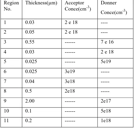
Table 1: Explain material parameters thickness for each layer of tandem solar cell.
Region No.
Thickness(µm) Acceptor Conce(cm-3)
Donner Conce(cm-3)
1 0.03 2 e 18 ----
2 0.05 2 e 18 ----
3 0.55 --- 7 e 16
4 0.03 --- 2 e 18
5 0.025 --- 5e19
6 0.025 3e19 ---
7 0.04 3e18 ---
8 0.5 2e18 ---
9 2.00 --- 2e17
10 0.1 --- 5e18
11 0.2 --- 1e18
[image:3.595.320.538.110.283.2]The multi-junction solar cell was designed by the aid of the silvaco software using (drift diffusion transport theory which make the basics for the designed model. The continuity, Poisson’s and transport equation are used as the fundamental basis for the Tandem cell design. These equations are normally describing the behavior of electron hole pair due to generation – recombination process. Figures (4) represent the photon image and dimension (Zoom in) of the upper section of the designed solar cell and the primary part of the lower section of the model.
Fig.4: Illustrate the exact dimensions for the designed solar cell.
Figures (5) shows the (I-V) transfer curve of the designed Tandem cell between the cathode current and the anode voltage
Fig.5: explain the (I-V) transfer curve of the designed cell.
It is found that the short circuit current Jsc is about 29.21mA/cm2 at zero volt anode voltage. This value of current keeps it’s worth over all anode voltage then start to decline significantly until it reach the lowest value at cell open circuit voltage equal to1.36V.The overall efficiency of the designed Tandem cell can be calculated by multiplying the short circuit current by the open circuit voltage and then by the fill factor of the cell.
It’s found that the cell has an efficiency of about 29.98% at Am1.5 irradiance with fill factor equal to 0.756 .
[image:3.595.53.282.253.472.2]The external quantum efficiency (EQE) is shown in Figures (6) as a fruition of optical wavelength, the cell has a minimum efficiency at (0.45 um) wavelength due to top cell effect. The bottom cell give a maximum respond at (0.7 um) wavelength, the overall efficiency of the cell is the total sum of the two effect of the top and bottom cells. The optimum spectrum is taken place at (0.35 – 0.6) um wavelength and decreased to its minimum value at 0.8 um, for the top cell. The spectrum of the cell is extended to the near infrared region and reach its minimum respond at (0.98 um) wavelength.
Fig.6: shows EQE with optical wavelength in the top and bottom cell.
[image:3.595.314.543.529.700.2] [image:3.595.54.282.593.738.2]29 Tandem cell is composed of multi-layers and the layers has
finite thickness and will absorb part of the incident photon , some of the photon will be transmitted the transmission of photon depend on the thickness of the solar cell and thinner cell will has more transmission energy than thick one. In tandem cell reducing the thickness of the top cell will participate to increase the current in the bottom cell at the expense of top short circuit current density if
Jscb > Jsct
Jscb = bottom cell J sc Jsct = top cell J sc
Then the top cell thickness can be minimized or reduced to the value that the two current ( J scb and J sct ) will be mathed together. So equaling the two current will enhance the efficiency of the tandem cell, it can be said that the total current density of the cell is determined by value of bottom cell current density and cannot exceed its value.
Figure (5) explain the (I-V) transfer curve between cathode current value at the electrode part and anode voltage, where the value of (Jsc) is about (29.21 mA/cm2) at zero volt anode. This value of current keeps its worth over all anode voltage,then start to decline significantly until it reaches the lowest value at (Voc = 1.36 V). Figure (6) shows the efficiency contour of Multi-junction (EQE) solar cells as a function of the optical wavelength for the tandem solar cell. The result shows that the cell has a maximum predicted efficiency at (0.45 µm) for the upper cell and (0.7 µm) for the bottom cell.
[image:4.595.54.282.470.643.2]The optimum spectrum have (0.35 – 0.6 µm) wavelength and decreased to its minimum value at (0.8 µm) for the top cell, while the perfect region (0.6 - 0.85 µm) and decreased to reaches its minimum optical wavelength value at (0.98 µm). Another important characteristic studied in this paper is the peak intensity and its influence with the optical wavelength.
Fig.7: peak intensity as a function of optical wavelength
It can be observed clearly that the active region lies between (0.4 – 0.8 µm), as well as the gradient appears to rise to its lowest value at (1.0 µm). Therefore, the wavelength after this value will have slight effect on the tandem solar cell efficiency.
4.
CONCLUSIONS
Although solar cells based on (Si) dominate the solar power world today, there are many ongoing studies on other alternative absorber materials apart from aforementioned
compounds, such as oxides, sulfides/selenides, nitrides, and many others. In this paper ( InAlGaP ) is studied as an absorber material for solar cells quite earlier , and this material is still considered as an interesting solar cell material if one can stabilize the structure.
In this research a theoretical study of the general issues related to the ( I-V) characteristic, external quantum efficiency and peak intensity as a function of wavelength of multi-junction tandem solar cells was carried out. Implementation of numerical simulations by using (silvaco-Atlas) program simulator of two-dimensional analysis for microelectronic and photonic structures for the analysis of solar cells allowed us to formulate the optimal design of different kind of multi-junction tandem solar cells, providing its most efficient operation.
The results obtained of the tandem cell are, the short-circuit current density ( Jsc ) of (29.21 mA/cm
2
) ,the fill factor is about 0.756 and the open circuit voltage ( Voc ) of (1.356 V) , the conversion efficiency is about ( 29.98%). It’s worth noting that all the results in this research were carried out along a wavelength (0 – 1.4 µm). The results prove the validity of using InGaP and GaAs for the design of high efficiency (III-V) tandem solar cells applications.
5.
REFERENCES
[1] G. L. Ara´ujo and A. Mart´ı, “Absolute limiting efficiencies for photovoltaic energy conversion,” Solar Energy Materials and Solar Cells, vol. 33, no. 2, pp. 213– 240, 1994.
[2] W. Shockley and H. J. Queisser, “Detailed Balance Limit of Efficiency of p-n Junction Solar Cells,” Journal of Applied Physics, vol. 32, no. 3, pp. 510–519, 1961.
[3] J. Nelson, J. Barnes, N. Ekins-Daukes, B. Kluftinger, E. Tsui, K. Barnham, C. T. Foxon, T. Cheng, and J. S. Roberts,“Observation of suppressed radiative recombination in single quantum well p-i-n photodiodes,” Journal of AppliedPhysics, vol. 82, no. 12, pp. 6240–6246,
[4] Lumb MP, Gonz_alez M, Bailey CG, Vurgaftman I, Meyer JR, Abell J, Yakes M, Hoheisel R, Tischler JG, Stavrinou PN et al. Drift-diffusion modeling of InP-based triple junction solar cells. P Soc Photo-Opt Ins 2013; 8620: 1-9.
[5] Baudrit M, Algora C. Modeling of GaInP/GaAs dual junction solar cells including tunnel junction. In: IEEE 2008 Photovoltaic Specialists Conference; {11-16 May 2008; San Diego, CA, USA}.
[6] M. A. Green, K. Emery, Y. Hishikawa, W. Warta, and E. D. Dunlop, “Solar cell efficiency tables ,” Progress in Photovoltaics: Research and Applications, vol. 23, no. 7, pp. 805–812,Jun.2015.
[7]Amin, N., Tang, M., Sopian, K., 2007. Numerical modeling of the copper–indium–selenium (CIS) based solar cell performance by AMPS-1D. In: Proc. IEEE 5th Student Conference on Research and Development, Malaysia.
[9] Jackson P, Hariskos D, Lotter E, Paetel S, Wuerz R, Menner R, Wischmann W, Powalla M. New world record efficiency for (In,Ga)Se2 thin-film solar cells. Photovolt. Res. Appl. 2011; 19: 894- 897.