ISSN Online: 2331-4249 ISSN Print: 2331-4222
DOI: 10.4236/wjet.2018.63035 Jul. 26, 2018 575 World Journal of Engineering and Technology
Study of Flow Field inside a Rectangular Air
Intake with Pointed Cowl for Different Back
Pressures at Mach 2.2
Shravan Koundinya Vutukuru
1, Sudip Das
2, Aleksandrs Urbahs
11Institute of Aeronautics, Faculty of Mechanical Engineering, Transport and Aeronautics, Riga Technical University, Riga, Latvia 2Birla Institute of Technology, Department of Space Engineering and Rocketry, Mesra, Ranchi, India
Abstract
Computations and Experiments were performed to get an understanding of the flow field around a rectangular supersonic air intake with pointed cowl [90˚] at different back pressures for Mach 2.2. The effect of Cowl shape on the ramp surface pressure distribution is discussed and compared with existing V-Notch [90˚] intake model at free exit condition. It was found that using pointed cowl [90˚] intake model, a better pressure recovery was achieved compared to the V-Notch [90˚] intake model at Mach 2.2. Both Pointed and V-Notch intake models showed good starting characteristics. For change in back pressure, the occurence of normal shock, flow separation zone and flow reversal were observed. All experiments are performed only for the Pointed cowl [90˚] intake model. All the 3-D computations were performed by using software available at B.I.T, Mesra, Ranchi.
Keywords
Back Pressures, Cowl, Intake, Mach, Pointed [90˚] Cowl, Clean Cowl, Schlieren, V-Notch [90˚] Cowl
1. Introduction
Air intake is a topic for active research. In a supersonic flow, there are multiple flow phenomena happening in and around the intake. It was found that the drag at the intake accounts for the significant drag for the overall aircraft, hence it is necessary to study the flow in and around the intake to develop an optimized de-sign model of the vehicle. In the present paper, Pointed Cowl [90˚] intake model was used since no such research work was ever performed or known (Figure 1).
How to cite this paper: Vutukuru, S.K., Das, S. and Urbahs, A. (2018) Study of Flow Field inside a Rectangular Air Intake with Pointed Cowl for Different Back Pressures at Mach 2.2. World Journal of Engineering and Technology, 6, 575-584. https://doi.org/10.4236/wjet.2018.63035
Received: May 20, 2018 Accepted: July 23, 2018 Published: July 26, 2018
Copyright © 2018 by authors and Scientific Research Publishing Inc. This work is licensed under the Creative Commons Attribution International License (CC BY 4.0).
DOI: 10.4236/wjet.2018.63035 576 World Journal of Engineering and Technology Figure 1. Intake Geometry for Pointed Cowl [90˚] model. (a) Ramp Geometric Details; (b) Cowl geometric Details; (c) Geometric details of the Side Plate.
The clean cowl intake model designed for Mach 2.2 with 2˚ inner cowl deflection is replaced with pointed [90˚] cowl and similarly with V-Notch cowl to obtain V-Notch [90˚] cowl intake model.
2. Literature Review
A brief description of the literature on the Air Intakes is discussed in this session. Advantage of Using bleed and Cowl bending for unstart suppression and per-formance by Das and Prasad [1]. The conclusions were –A bleeding of 1.8% of the air alleviate the problem of unstart, definite increase of performance was achieved using bleed and cowl bending. Suggested that cowl deflection could be an alternative for air intake bleed. Starting characteristics for intake with cowl deflection were also studied by Das and Prasad [2], concluded that cowl defec-tion as an alternative to the bleeding for the intake model. Two dimensional si-mulations corresponding to different cowl bending was studied by Das and Pra-sad [3] concluded that the increase in cowl deflection angle increased the per-formance for the intake model with pressurized exit and small deflection led to good pressure recovery.
DOI: 10.4236/wjet.2018.63035 577 World Journal of Engineering and Technology
Mach 6.0. [5]. It was concluded that the wall cooling is important for the intake to start and the pressure recovery is independent of the Reynolds number.
Study was performed on the Nose bluntness and controlled roughness on the flow at Mach 5.98 by Cubbage [6] he observed that controlled roughness and nose bluntness had no influence on surface pressure. Computational analysis on losses due to shock detachment on the cowl leading edge and the influence of the detach shock on the characteristics of overall flow at the exit was studied by Smart and White [7], on a three dimensional hypersonic air intake.
Studies on moving cowl at hypersonic speeds on air intake were performed by Donde [8]. It was concluded that after the unstart of the air intake the cowl needs to be rotated by an angle of 15.70 and then should be brought to desired position for the start of the air intake.
A detail experimental study of shock-wave interference heating on a cylin-drical leading edge is presented in this paper by Allan R. Wieting and Michael S. Holden [9]. At Mach 6.3, 6.5 and 8.0. The peak heat transfer rates and pressure were 2 - 25 times the undisturbed flow stagnation point levels and was also ob-served that the peak levels and their gradients increased as Mach number in-creased.
A study on quasi axis symmetric scramjet models designed at Mach 6 and Mach 8 was performed by Katsu Yoshi Tanimizu, D. J. Mee and R. J. Stalker [10]. It was concluded that for the both the models the Drag – co-efficient de-creased with the Increasing Mach. The Final Conclusion was that no significant differences in the drag co-efficient were observed for the two different models at Mach 6.
DOI: 10.4236/wjet.2018.63035 578 World Journal of Engineering and Technology
Variable Inlet with a design Mach 3.0 at Transonic speeds and varying Rey-nolds number on a 2-D mixed compression intake was performed by Wong, et al.[12]. It was concluded that 1-D invincible theory is adequate for the predic-tion of Drag due to the viscous effect on the Ramp Surface.
Shape Transition for Intake from Rectangular to Elliptical was studied by Smart [13]. A highly significant Notch cowl was used to allow for self-Starting at high Ramjets take over speeds.
The Increase in Pressure recovery was good for a V-Notch Cowl [90˚] intake model compared to Pointed [90˚] cowl at Mach 2.0, [14] Urbahs, S. Das, Shra-van koundinya Vutukuru, Kristine, the pointed cowl showed better starting characteristics at off design conditions for a given Intake Model.
Transition Modelling for Hypersonic air Intake flows in Scramjet applications was studied by Sarah Frauholz, et al.[15]. The important conclusion was that at Off-design condition with the cowl position, the leading edge shock had im-pinged on the underside of the cowl and for similar compression ramp angles and side walls there was a homogenous interior flow. The investigations of the transition model showed the importance of right prediction of the lami-nar-turbulent transition. A better agreement for the SST transition model was observed to the experimental data for the pressure co-efficient.
The flow field over the pointed cowl [90˚] intake model is not investigated. All the required Experiments and Simulations are performed for Pointed cowl [90˚] Intake model and Good comparison is made with available literature at B.I.T, Mesra so as to get the effects of Cowl shape on the Ramp surface pressure Dis-tribution.
3. Research Methodology
All experiments were performed for the Pointed Cowl [90˚] intake model with the Wind Tunnel test facility available at Birla Institute of Technology, Depart-ment of Space Engineering and Rocketry. Ranchi, India.
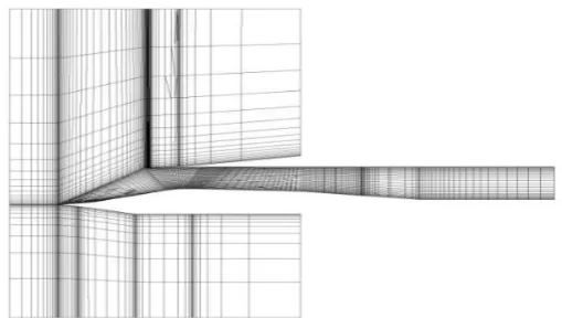
Computations were performed by using ANSYS FLUENT CFD. The geometry was made in GAMBIT and Meshed (Figure 9), defining the boundary condi-tions for the model (Figure 12). A free stream turbulence intensity of 0.5% was specified at the inlet. K-ω Turbulence model is used and No slip boundary con-dition is imposed at the walls. The minimum spacing at the walls in Y-direction was at the order of 0.15 mm. A total of 3, 45,800 number of cells, structured mesh (Figure 10) and the residuals were converged to 10−3.
4. Results and Discussion
Three-dimensional computations were performed to get an understanding of the complex flow inside the intake at Mach 2.2 for pointed cowl [90˚] and v-notched cowl [90˚] intake model. Further, computations are performed on the intake Pointed cowl [90˚] model at various back pressures.
DOI: 10.4236/wjet.2018.63035 579 World Journal of Engineering and Technology
The density contour is shown in Figure 2. The series of compression shocks generated by the Ramp surface gets reflected almost at the tip of the cowl. The location of cowl tip shock on the ramp surface is observed to move inside the duct. Distinct shock reflections inside the duct can be seen which cause for the subsequent change in the pressure distribution along the ramp surface. Figure 8 shows the shock reflections inside Pointed cowl intake model at Mach 2.2. 2) Flow inside the Intake with V-Notched Cowl (90˚) at Mach 2.2
Density contour for V-Notch cowl [90˚] intake model is shown in Figure 3. The effect of notch angle could be seen clearly by observing the location of the cowl tip shock on the ramp surface. Further distinct shock reflections inside the duct represented by subsequent jump in pressure can be seen from Figure 3 and Figure 4. This clearly indicates a proper diffusion occurring inside the intake. 3) Pressure Distribution for the two intake model at the Ramp center.
Figure 4 provides a comparison of two intakes ramp surface pressure distri-butions. The pressure is constant along the first ramp in all the cases. A drop in peak pressure value seen for both notch and pointed cowl is due to the weakening of the cowl shock. There is a sudden decrease in pressure at the shoulder of the intake due to the expansion corner. A smaller peak value in case of Pointed cowl model indicates that the cowl tip shock on the ramp has moved downstream compared to the V-Notch cowl [90˚] intake model.
At Mach 2.2, for the Pointed [90˚] cowl intake model the measured Pressure recovery was 83.9% which was found to be more than Notch and Clean cowl intake models.
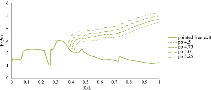
4) Pressure Distribution at the Ramp Centre with varying Backpressures for Pointed Cowl Intake model at Mach 2.2 (Figure 6).
The back pressure is applied in terms of exit static pressure ratio Pe/P∞. It was found that at the ratio of Pe/P∞ = 5.25, the normal shock was observed near to the throat region, there was massive flow separation downstream of the shock (Figure 5).
5) Experimental Results for pressurized exit for pointed cowl [90˚] at Mach 2.2 (Figure 7).
DOI: 10.4236/wjet.2018.63035 580 World Journal of Engineering and Technology Figure 3. Density contour for V-Notched cowl [90˚] intake model.
[image:6.595.176.537.539.693.2]Figure 4. Pressure distribution for the intake model at the centre of the Ramp at Mach 2.2.
Figure 5. Density contour for the pointed cowl at Pe/P∞ = 5.25 at the exit of the intake.
DOI: 10.4236/wjet.2018.63035 581 World Journal of Engineering and Technology Figure 7. Measured pressure along the ramp at mach 2.2 for the pointed cowl model with and without throttle at the intake exit.
[image:7.595.244.503.247.396.2]Figure 8. Schlieren flow visualization for the Pointed cowl at Mach 2.2 at free exit condition.
Figure 9. Surface grid for pointed cowl intake model.
[image:7.595.247.502.562.706.2]DOI: 10.4236/wjet.2018.63035 582 World Journal of Engineering and Technology Figure 11. Pointed cowl intake with the conical plug for throttling.
Figure12. Boundary conditions and computational domain specifications for the intake model. (a) Boundary conditions; (b) Domain specifications.
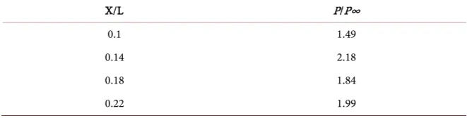
Table 1. Static pressure measured along ramp surface for the pointed cowl at Mach 2.2 for free exit.
X/L P/P∞
0.1 1.49
0.14 2.18
0.18 1.84
[image:8.595.208.539.641.730.2]DOI: 10.4236/wjet.2018.63035 583 World Journal of Engineering and Technology Continued
0.26 1.61
0.29 1.99
0.33 2.44
0.37 2.80
0.41 2.80
0.46 2.40
0.48 2.34
0.56 2.28
0.66 1.38
0.78 1.45
0.82 1.88
5. Conclusions
The following important conclusions were drawn for the Pointed Cowl [90˚] in-take model at Mach 2.2.
Series of compression shocks generated by ramp surface got reflected at the tip of the cowl and distinct shock reflections inside the intake duct resulted in better starting characteristics for pointed cowl intake over V-Notch intake model and also good pressure recovery was measured for the pointed cowl which was an advantage over V-Notch [90˚] cowl intake model at free exit condition. Si-mulation of engine operating conditions has been achieved by throttling a plug at the exit of the intake. Similar observations could be achieved in computations by application of a back pressure at the exit. With change in back pressure and with the differentthrottle condition at the exit, the normal shock location could be changed.
Future work includes pressure distribution along the ramp surface for intake model with different cowl angles and also flow analysis and pressure recovery by introducing a 3D Bump on the ramp surface.
References
[1] Das, S. and Prasad, J.K. (2010) Unstart Suppression and Performance Analysis of Supersonic Air Intake Adopting Bleed and Cowl Bending. Journal of Institution of Engineers (India), 91, 27-35.
[2] Das, S. and Prasad, J.K. (2010) Starting Characteristics of a Rectangular Supersonic Air Intake with Cowl Deflection. Aeronautical Journal, 114, 177-189.
https://doi.org/10.1017/S0001924000003626
[3] Das, S. and Prasad, J.K. (2009) Effects of Cowl Deflection Angle in a Supersonic Air Intake. Defence Science Journal, 59, 99-105. https://doi.org/10.14429/dsj.59.1496 [4] Mahapatra, D. and Jagadeesh, G. (2009) Experimental Investigation of Cowl Shape
DOI: 10.4236/wjet.2018.63035 584 World Journal of Engineering and Technology [5] Goldberg, T.J. and Heffner, J.N. (1971) Starting Phenomena for Hypersonic Intakes with Thick Boundary Layers at Mach 6. NASA Technical Note, NASA TN D-6280. [6] Cubbage, J.M. (1965) Effect of Nose Bluntness and Controlled Roughness on the
Flow on Two Hypersonic Intake Centre Bodies without Cowling at Mach 5.98. NASA Technical Report, 1-64.
[7] Smart, M.K. and White, J.A. (2002) Computational Investigation of the Perfor-mance and Back Pressure Limits of a Hypersonic Intake. 40th AIAA Aerospace Sciences Meeting and Exhibit, Reno, NV, 4-17 January 2002, 1-15.
https://arc.aiaa.org/doi/10.2514/6.2002-508
[8] Prakash, D.P. (2006) Hypersonic Intake Studies. M Tech Dissertation, Department of Aerospace Engineering, Indian Institute of Technology, Bombay.
[9] Weiting, A.R. and Holden, M.S. (1989) Experimental Shock-Wave Interference Heating on a Cylinder at Mach 6 and 8. AIAA Journal, 27, 1557-1565.
https://arc.aiaa.org/doi/10.2514/3.10301 https://doi.org/10.2514/3.10301
[10] Tanimizu, K., Mee, D.J. and Stalker, R.J. (2007) Comparison of Drag Measurements of Two Axisymmetric Scramjet Models at Mach 6. 16th Australian Fluid Mechanics Conference, Crown Plaza, Gold Coast, Australia, 2-7 December 2007, 1299.
[11] Re, R.J. and Abeyounis, W.K. (1993) Wind Tunnel Investigation of Three Axisym-metric Cowls of Different Lengths at Mach Numbers from 0.60 to 0.92. NASA Technical Memorandum 4488.
[12] Wong, N.D. and Anderson, W.E. (1973) Experimental Investigation of Large-Scale, Two-Dimensional, Mixed Compression Inlet System. NASA TN D7445, Washing-ton, DC.
[13] Smart, M.K. (1999) Design of Three-Dimensional Hypersonic Intakes with Rectan-gular to Elliptical Shape Transition. Journal of Propulsion and Power, 15, 408-416. https://doi.org/10.2514/2.5459
[14] Urbahs, A., Das, S., Vutukuru, S.K. and Carjova, K. (2017) Investigation of Flow Field around Pointed Cowl at Mach 2.0. Transport and Aerospace Engineering, 5, 75-82. https://doi.org/10.1515/tae-2017-0021
[15] Frauholz, S., Reinartz, B.U., Muller, S. and Behr, M. (2014) Transition Modeling for Hypersonic Air Intake Flows in Scramjet Applications. 6th European Conference on
Computational Fluid Dynamics, June 2014, 29 p.
Nomenclature
L = Overall Length of the model; X = Distance from leading edge; P = Static pressure;
P∞= Free steram pressure;
Pe = Back pressure (Pb);
At = Throat area;
Ae = Exit area;
![Figure 1. Intake Geometry for Pointed Cowl [90˚] model. (a) Ramp Geometric Details; (b) Cowl geometric Details; (c) Geometric details of the Side Plate](https://thumb-us.123doks.com/thumbv2/123dok_us/9278960.420599/2.595.213.536.73.345/geometry-pointed-geometric-details-geometric-details-geometric-details.webp)