Comparative Study of Load Frequency Control using PID and Fuzzy- PID
Controller in Power System
Kavita Choudhary
1, Dr. Sumer Singh
21
Student IEEE member and Assistant Professor, EE Dept., Bhartiya Institute of Engineering and Technology College,
Sikar, India
2
Associate Professor, EE Dept., Bhartiya Institute of Engineering and Technology College, Sikar, India
---***---
Abstract -
In this paper, load frequency control is one of the efficient ways to solve various problems in power system. The different configuration of models and control techniques are applied for load frequency control have been addressed which are applicable for generation system. An interconnected system for two areas is designed and simulated by using fuzzy logic controller for improved performance parameter. Like:-setting time, overshoot value, and undershoot value and maximum range over the conventional PID controller. The control methodology assures that the steady state error of frequency and exchange of tie-line power of area maintain within prescribed limit. The working of the two area system incorporating these controllers are simulated using MATLAB/Simulink packages.Key Words
:
Fuzzy logic control, conventional PID controller, fuzzy PID controller, load frequency control, membership function, inter-connected two-area system. Tie-line power deviation.1.
INTRODUCTION
Load frequency control is addressed as one of the most important services in electric power system design and it has been used for several decades to meet two main objectives, viz., maintaining the system frequency and the tie line power deviations within specified values.LFC is generally considered as secondary level control and also a dominant operation in the area of automatic generation control (AGC).
Power system operation considered so far was under conditions of steady load. However, both active and reactive power demands are never steady and they continually change with the rising and falling trend.(maximum permissible change in
power frequency is
±0.5HZ).The flows of active power and reactive power in transmission network are fairly
independent of each other and are influenced by different control action. Hence, active power control is closely
related to frequency control and reactive power control is closely is related to voltage control in power system.
As constancy of frequency and voltage are important factor in determining the quality of power supply, the
control of active power and reactive power is vital to the satisfactory performance of power systems.
ACTIVE POWER AND FREQUENCY CONTROL
For satisfactory operation of a power system, the frequency should remain nearly constant. Relatively close control of frequency ensures constancy of speed of induction and synchronous motors. The frequency of a system is dependent on active power balance. As frequency is a common factor throughout the system, a change in active power demand at one point is reflected throughout the system by a change in frequency. Because there are many generators supplying power into the system, some means must be provided to allocate change in demand to the generators. In an interconnected system with two or more independently controlled areas, in addition to control of frequency, the generation within each area has to be controlled so as to maintain scheduled power interchange. The control of generation and frequency is commonly referred to as load frequency control (LFC).combination of active power and frequency control (p-f) is generally known as load frequency control.
In power system network consider of maintain frequency constant and regulation of tie-line power exchanger error. The frequency depends on speed.
2.
system description and models a.system models1)thermal unit
Transfer function :-a) Non-Reheat turbine
b)Reheat Steam turbine
2)Hydro unit
A hydro turbine converter potential energy converter potential energy of the water into kinetic energy than this energy converter into rotating energy, than it converter into electrical energy by generators. the governors of hydro units require large transient droop compensation for stable speed control performance, therefore hydro turbine are modeled in such a way that they have relatively large transient droop with long resetting times.
Transfer function:-
Transient droop compensation:-
The control objectives to be fulfilled are as follows:-
Each control area as much as possible ought to provide its own load demand and transfer the power through tie line must be done only in the case of the demand of that area being lower than the generation of the units in the specified area.
All control areas should respond to the change in load frequency control.
controller structure and objective
minimized.ITSE based controller provides larger controller output for a sudden change in set point which is not advantageous from controller design point of view. It has been reported in literature that ITAE gives a better performance compared to other integral based performance criteria [32],Therefore, ITAE is used as objective function in this paper to optimize the scaling factors and proportional , integral and derivative gains of fuzzy PID controller.Expression for the ITAE objective function is depicted in equation (3).
(i) Conventional PID controller
Proportional integral derivative controllers play a major role in industrial process control.because more than 90 percent of process in different electrical industries are controlled by PID controllers these days.the PID controller are used for minimizing the frequency deviations in the multi area power system.
(ii) Fuzzy PID based controller
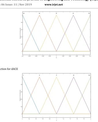
Fig.2 Block diagram for Fuzzy logic controller Membership function for ACE
Membership function for dACE
Table 1. Fuzzy Logic Controller Rules For Fuzzy PID based Controller
ACE/
ACE
NL NS ZZ PS PLNL S S M M L
NS S M M L VL
ZZ M M L VL VL
PS M L VL VL VVL
[image:4.596.106.446.47.473.2]3.
Result and Simulation Model
Fig:3- simulation model diagram for two area reheat power system
Result discussion
Fig4:- Deviation in frequency in area1
Comparative table
parameters System with PID
controller System controller with Fuzzy-PID
Undershoot(Hz) 0.082 0.027
Settling Time(sec) 15 10
Fig.5: Frequency Deviation of area2
Comparative table
parameters System with PID
controller
System with Fuzzy-PID controller
Undershoot(Hz) 0.082 0.027
Settling Time(sec) 15 10
4.
Conclusion
Investigation of two area system has been done with PID and Fuzzy-PID logic controllers. Considering the disturbance as 1% the result for different cases are compared and it shows that fuzzy-PID controller gives improved dynamic response than PID controller. With the aid of fuzzy-PID controller the transients in the frequency response reduced to a great extent.
5. REFERENCES
1) System and Control by stanislaw h. zak.
2) F.L. Lewis and V.L. Syrmos, Optimal control, Prentice Hall, Englewood Cliffs, New Jersey, 1995.
3) J.Kumar, Kah-Hoe Ng and G. Sheble, “AGC Simulator for price-based Operation Part 1: A model, “IEEE Trans. On
Power Systems, vol. 12, no. 2, May. 1997.
4) C. Edwards and S. Spurgeon, Sliding Mode Control: Theory and Applications. Taylor and Francis, 1998.
5) Q. Ha, “A fuzy sliding mode controller for power system load-frequency control,” in Second International
© 2019, IRJET | Impact Factor value: 7.34 | ISO 9001:2008 Certified Journal
| Page 52
10)D.Rerkpreedapong and A. Feliachi, “Decentralized Load Frequency Control for Load Following Services, “IEEE
Power Engineering Society Winter Meeting, vol. 2, no.1, pp 1252- 1257, Jan. 2002.
11)
G. Monsees, “Discrete-time sliding mode control,” Ph.D.dissertation, Delft University of Technology,
Netherlands, 2002.
12)A.Khaki Sedigh, Modern Control Systems, University of Tehran Press, 2003.
13)
F. Liu, Y.H.Song, J.Ma, S.Mei and Q Lu, “Optimal LoadFrequency Control in restructured power Systems,”
Distribution, vol. 150, no. 1, pp. 87-95, Jan. 2003
14)B. Stojkovi´, “An original approach for load-frequency control – thec winning solution in the second UCTE
synchronous zone,” Electric Power Systems Research, vol. 69, no. 1, pp. 59–68, April 2004.
15)M. Alrifai, “Decentralized controllers for power system load frequency control,” ICGST International Journal on
Automatic Control and System Engineering, vol. 5, no. 2, pp. 1– 16, 2005
16)A. Demiroren and H.L. Zeynelgil, “GA application to optimization of AGC in tree-area power system after