THE
PIC~
SYSTEM
'.ASSEMBLY REFERENCE
MANUALR83
. ;;,
'f,
> )
S Y S T E M S
© 1987 PICK SYSTEMS
PICK SYSTEMS
1691 Browning Ave.
Irvine, California 92714
CONFIDENTIALITY AND NON-DISCLOSURE AGREEMENT
I The course of Business dealings between and
PICK SYSTEMS, it has become necessary for PICK SYSTEMS to provide
with certain trade secrets, know-how and other
other proprietary data and material information.
This may include but is not limited to documentation, engineering
specifications, test procedures, maintenance documentation,
schematics, and logic diagrams. PICK SYSTEMS considers all such
information and materi~l as proprietary to and a trade secret of PICK
SYSTEMS.
recognizes and agrees with such classification
and agrees to treat ALL such information and material received from
PICK SYSTEMS as proprietary to and trade secrets of PICK SYSTEMS.
Furthermore agre.s not to disclose,
divulge, copy or otherwise make available to any third party either
directly or indirectly any information or material received from PICK
SYSTEMS without prior written approval.
DATE
COMPANY
TITLE'
* * *
CHANGES TO VIR.OSYM* * *
There are several changes to the VIR.OSYM file that should be made before using the ASSEMBLER account. These changes solve problems with the BRANCH·DECREMENTING class of instructions. The complete list of these instructions is:
BD:DDL BD:DNL BD:HHL BD:HNL BD:TNL BD:TTL
I·
,I
I
I
If
I
r
I r'i
I
I
I
I-I
D
"
n
n
n
n
n
n
n
n,:,!'
Ii
r
; ~..:
GENERAL INSTRUCTIONS FOR
ASSEMBLING PROGRAMS ON THE PC-XT OR PC-AT General Information - How to Load It and Use It
Use EX'i'REME caution in creating and ~oading~~.semblycode!JJlm~!,Q~~rl!~~~.TNri tten assembly code can cause severe problems on your system including loss of data, group format errors, and system crashes. Pick Systems cancels ALL warranties on any computer system that is running user written assembly code.
LOADING THE ASSEMBLY ACCOUNT
The assembler floppies 1 and 2 have an account containing all the necessary files to'create, assemble and load Pick assembler code for the IBM PC-AT 2.0 and XT 2.0 releases. Follow these instructions to install and use the assembler account.
' . -'0' "<
1. Ensure that you have at least 700 frams of disk space available. 2. Mount the floppy #1 in the A: diskette drive.
3. Logto SYSPROG and type 'T-ATT' and ensure that the drive did attach. 4. Type 'ACCOUNT-RESTORE ASSEMBLER'. Load floppy #2 in drive when requested
and type 'C'.
5. Type 'ASSEMBLER' to the 'ACCOUNT NAME ON TAPE' prompt.
6. Ensure that the account restored properly.
ASSESMBLING AND LOADING USER SOURCE CODE
The first step is to LOGTO the ASSEMBLER account. Before attempting to assemble source code you must add two items to the ERRHSG file. The form of these items can be obtained by typing ADDENDUM 003 at TCL. The Pick assembler for the IBM PC-ArlXT uses the same Pick source code as all other Pick Systems. Use the following
instructions to assemble your code.
1. Load your source code into the file 'VIR.SM'. 2. Define the type of assembly (XT or AT) by:
a. )SET-AT - for AT b. )SET-XT - for XT
3. Use the 'AS' verb to do assemblies.
a. To assemble one item: )AS itemname
b. To assemble a lis t )GET -LIST lis tname )AS
; 4. The assembled ccode is stored according to assembly type: a. In file NAT.SMS.AT - for AT
b. In file NAT.SMS.XT - for XT
5. Check for Translation (1st pass) assembly errors by: )LIST VIR.SM item/s
The 'asm err' column will show errors.
6. Check for Optimization and Native Assembly errors (2nd pass) by: )LIST NAT.SM item/s
The 'opt err' and 'asm err' columns will show errors. It is also important to check the 'obj siz dec' column to insure the final assembled object is NOT more than 2048 bytes.
~I\
I:
I
I
I
D
D
O~
II
Uj
~ .
IL
n
n
n
n
n
U
iI
nl
BD:DDL 001 P
002 G,4,4,8,8 A2;3,A3;3,0,48 003 O@YI
004 0 HOV @BI(2),CX 005 0 XCHG CH,CL 006 0 LDA @B2(2) 007 0 XCHG AU,AL 008 0 SUB AX,CX 009 0 HOV CX,DX,SAVE 010 0 XCHG CH,CL OIl 0 HOV CX,@BI(2) 012 0 HOV @BI,CX 013 0 XCHG CH,CL 014 0 LDA @B2 015 0 XCHG AU,AL 016 0 SBB AX,CX
017 0 SUIS O,CX ADDITIONAL LINE 018 0 XCHG CH,CL
019 0 HOV CX,@BI 020 O@CI
021 0 OR DX,DX 022 0@C3
023 O@LI JUS @03 024 O@L2 EOU
*
BD:DNL 001 P
002 G,4,12,8,8 A2;3,0,44,X'CI' 003 O@YI
004 0 HOV @BI(2),CX 005 0 XCHG CH,CL
006 0 HVI X'@A(02;CVX;CDL)',AX 007 0 HVI X'@A(02;CVX;CDH)',DX 008 0 SUB AX,CX
009 0 HOV CX,AX SAVE 010 0 XCHG CH,CL OIl 0 MOV CX,@BI(2) 012 0 MOV @BI,CX 013 0 XCHG CH,CL 014 0 SBB DX,CX
015 0 SUIS O,CX ADDITIONAL LINE 016 0 XCHG CH,CL
017 0 MOV CX,@BI 018 O@CI
019 0 OR AX,AX 020 O@C3
021 O@LI JUS @03 022 O@L2 EOU
*
BD:HHL 001 P
002 G,4,4,8,8 A2;3,A3;3,0,9 003 O@YI
004 0 LDAB @B2 005 0 SUBB AL,@BI
006 0 SUIB O,@BI ADDITIONAL LINE 007 0 JCS @CO,@03
BD:HNL 001 P
002 G,4,4,8,8 A2;3,0,0,7 003 O@Vl
004 0 SUIB @02,@Bl NEV OPCODE IS "SUIB", ORIGINAL VAS "SBIB" 005 0 SUIB O,@Bl ADDITIONAL LINE
006 0 JCS @CO,@03 BD:TNL
001 P
002-G,4,12,8,8A2;l,G,18,*'C2' 003 O@Vl
004 0 MOV @Bl,CX 005 0 XCHG CH,CL 006 0 SUI @02,CX
007 0 SUIS O,CX ADDITIONAL LINE 008 0 XCHG CH,CL
009 0 MOV CX,@Bl OlO 0 JCS @CO,@03
BD:TTL 001 P
002 G,4,4,8,8 A2;3,A3;3,0,21 003 O@Vl
004 0 MOV @Bl,CX 005 0 XCHG CH,CL 006 0 LDA @B2 007 0 XCHG AH,AL 008 0 SUB AX,CX
009 0 SUIS O,CX ADDITIONAL LINE 010 0 XCHG CH,CL
011 0 MOV CX,@Bl . 012 0 JCS @CO,@03
I
I
I:
I
I
I
DI
Hi
n
n
n
n
n
n
n
n
r
r
I
I
SECTIONI
11. 1 1.2
I~
1.2.1L2.2
1.2.3
I
1. 2.3. 1 1.2.4 1.3 1.4U
1.51.6 1.7
n
1.91.9. 1
il
2 2.12.2 2.2.1
n
2.2.22.2.3 2.2.4
n
2.2.52.2.6 2.2.7
n
2.2.92.2.9 2.2.10 2.2.11
n
2.2.122.2.13 2.2.14
a
2.2.152.2.16 2.2.17 2.2.19
n
2.2.19.
2.3 2.3.10
2.3.2 2.3.3 2.3.4n
2.3.52.4 2. 4. 1 2.4.2 2.4.3 2.4.4 2. 5 2.5.1 2.5.2 2.5.3 2.5.4 2. 5. 5 2.5.6
TABLE OF C~4TENTS
THE ASSEMBLER . PICK ASSEMBLE.R SOURCE LANGUAGE LABEL FIELD. . OPERATOR FrELU OPERAND FIELD .
OPERAND FIELD EXPRESSIONS COMMENT FIELD . . . , . .
ASSEMBLING SOURCE CODE : 'AS' VERB
LISTING ASSEMBLY PROGRAMS: 'MLIST' VERB LOADING ASSEMBLED MODES: 'MLOAD' VERB
VERIFYING A LOADED PROGRAM MODE: 'MVERIFY' VERB STRIPPING THE SOURCE CODE: 'STRIP-SOURCE' VERB. CROSS REFERENCE CAPABILITIES 'CROSS-INDEX' VERB CROSS REFERENCE CAPABILITIES: 'XREF' VERB
MACHINE INSTRUCTIONS PICK ASSEMBLY LANGUAGE ARITHMETIC OPERATIONS Load (LOAD) . . . . . Load Extended (LOADX) Store (STORE) . . . . Zero (ZERO) . . . . . One (ONE) . . . . Add to Accumulator (ADD) Add Extended (ADDX) . . .
Increment Storage by One (INC) Add to Storage <INC) . . . . . Subtract from Accumulator (SUB) Subtract Extended (SUBX)
Decrement Storage by One (DEC) Subtract from Storage (DEC) Mul tip ly (MUL) . . . . . Multiply Extended (MULX) Divide (DIV) . . . . Divide Extended (DIVX) Negate (NEG) . . . . . Move (MOV) . . . . CHARACTER INSTRUCTIONS
Move Character to Character (MCC) . Move Character to Incrementing Character (MCI) Move Character Incrementing and Count (MCI) . . Move Incrementing Char~cter to Character (MIC)
Move Incrementing Character to Incrementing Character (MIl)
LOGICAL INSTRUCTIONS Logical Or (OR) .
Logical Exclusive Or (XOR) Log i cal And (AND) . . . . . Shift (SHIFT) . . . . BRANCHING INSTRUCTIONS Branch Unconditionally (B) Enter External Mode (ENT) . Subroutine Call (BSL) : . . Return from Subroutine (RTN) Branch character instructions Branch Character E~ual (BCE)
J' •
[image:10.612.76.571.44.785.2]2.5 .. 7 2.5.8 2.5.9 2. 5. 10 2.5.11 2. 5. 12
2. 5. 13 2. 5. 14 2.5. 15
2. 5. 16
2; 5;1-'1 2. 5. 18 2.5. 19 2.5.20 2.5.21 2.5.22 2.5.23 2.5.24 2.5.25 2.5.26 2.5.27 2.5.28 2.5.29 2.5.30 2.6 2.6.1 2.6.2 2.6.3 2.6.4 2.6.5 2.6.6 2.6.7 2 .. 6.8 2.6.9 2.6.10 2.6.11 2.7
2. 7. 1
2.7.2 2.7.3 2.7.4 2.8 2.8.1 2.8.2 2.8.3 2.8.4 2.8.5 2.8.6 2.8.7 2.8.8 2.8.9 2.9 2.9.1 2.9.2 2.9.3 2.9.4 2.9.5
2. 10 2. 10. 1 2.10.2 2.10.3
Branch.~h~racte~ Un~~ual (BtU) Branch. Ch.r~cte~Low (aCLJ
Branch Character Less. than
or
Ect",al (BClE)Branc~Characte+ Hi)h (BCH) ' . '. Branch Character' High or E~liIctl (BCHE) Branch Character Numeric (BCN)
Branch Character Not Numeric (BCNN) Branch Character Hexadecimal (BCX)
Branch Character Not Hexadecimal <BCNX) Branch Character Alphabetic (BCA)
Branch Character Not Alphabetic~~B-CNA>-·· . . • • . . . -.; Branch if
Zero
(BZ) .Branch if Not
Zero
(BNZ)Branch if less than
Zero
(BLZ)Branch if less than
or
E~ual toZero
(BlEZ) Branch if E~ual (BE)Branch if Une~ual (BU) Branch if Less than (Bl)
Branch if Less than or E~ual (BLE) Branch if High (BH)
Branch if High or E~ual (BHE) . Branch Decrementing Not
Zero
(BDNZ)Branch Decrementing less than
Zero
(BDlZ)Branch Decrementing Less than or E~ual to
Zero
(BDlEZ) STRINQ-HANDlINQ INSTRUCTIONSScan to Delimiter (SID and SDD)' Scan to Delimiter and Count Scan to Count . . . Scan to count or delimiter Move String to Delimiter
Move string to Delimiter and Count Move String to Count .
Move String to Register . . Move String to Count
or
Delimiter Scan, Counting Delimiters (SICD)Branch on comparing strings; BSTE and BSTU BIT INSTRUCTIONS
Set Bit (SB) .
Zero
Bit (ZB) .Branch Bit Set (BBS) Branch Bit
Zero
(BBZ) REQISTER INSTRUCTIONSLoad Absolute Difference (LAD) Increment Address Register (INC) Decrement Address Register (DEC) Increment Storage Register (INC) Decrement Storage Register (DEC) Set Register to Address (SRA) Move Register to Register (MOV)
Exchange Register with Register (XRR) Setup Register (SETUP)
CONVERSION INSTRUCTIONS . Move Binary to Decimal (MBD)
Move Binary to Hexadecimal (MBX and MBXN) Move Decimal to Binary (MOB)
Move Hexadecimal to Binary (MXB) .
Move Floating-Point String to Binary (MSDB and MSXB) OTHER INSTRUCTIONS .
Read Input Gueue (READ) . . . Write to Output Gueue (WRITE) Release Time Guantum (RGM)
20 20 . 21 21 21 21 21 21 22 22
.. ~ 22~
22 22 22 22 23 23 23 23 24 24 24 24 24 25 26 26 26 26 27 27 27 27 28 29 31 32 32 32 32 32 33 33 33 33 34 34 34 34· 34 35 36 36 36 36 37 37. 38 38 38 38
I
1
I·
I
o
n
n
n
n
n
n
n
n.·
Ii.
,
.r
i3.1 3.1. 1 3.1.2 3; 1. 3 3.1.4 3.1. 5 3.1.6
3. 1. 7
3.1.8 3.2 3.3
3. 3. 1
3. 3. 2
3~3.3 3.3.4 3.3.5 3.3.6 3.3.7 3.3.8 3.3.9
3. 3. 10 3.3.11 3.3.12 3.3.13 3.3.14 3.3.15 3.3.16 3.3.17 3.3.18 3.3.19 3.3.20 3.3.21 3.3.22 3.3.23 3.3.24 3.3.25 3.3.26 3.3.27 3.3.28 3.3.29 3.3.30 3.3.31 3.3.32 3.3.33 3.3.34 3.3.35 3.3.36 3.3.37 3.3.38 3.3.39 3.3.40 3.3.41 3.3.42 3.3.43 3.3.44 3.3.45 3.3.46 3.3.47 3.3.48 3.3.49 3.3.50 4
SYSTEM SOFTWARE . Introduction
Address Registers Re-entrancl:I . . .
Work-spaces or Buffers
Defining a Separate Buffer Area Usage of XMODE . . . . .
Initial Conditions . . . Special PSYM Elements. . DOCUMENTATION CONVENTIONS System subr~utines
ATTOVF . . . . BLOCK-SUB. . . CONV - CONVEXIT . DLINIT . . . . . DLINITl . . . . . ENGLISH INTERFACE GETBUF - G3 . . GETIB - GETIBX GETITM GETOPT GETOVF GETUPD GNSEGI GNTBLI HGETIB HSISVR? INITTERM IROVF .
. .
. ..
.
.
. .
.
. .
.
.
.
. . .
.. . .
.ISINIT LINESUB MD415 . NEWPAGE
NEXTIR - NEXTOVF OPENPFILE
PCBFID
PCRLF . . . . PINIT . . . . PONOFF . . . PPUT (l,SPOOLADD)*
RESETTERM
PRIVTSTl - PRIVTST2 - PRIVTST3 PRNTHDR . . . .
PROC User Ex its . PRTERR . . .
RELBLK - RELCHN - RELOVF RETI RETIX RETIXU
SETLPTR - SET TERM SETUP TERM . . . . SLEEP - SLEEP SUB SORT . . . . TCL-II MD200 MD201 TIME - DATE - TIMDATE TPREAD TPWRITE
TSINIT . . . . . UPDITM - UPDITMX WHOSUB . . . . . WRAPUP PROCESSOR WRTLIN WRITOB WT2 WSINIT
WTBMS. . . . . XISOS . . . . . SYSTEM DEBUGGER
4.1
. 4. 1. 1
4.1.2 4.1.3 4.1.4 4.1.5 4.1.6 4.1.7 4.1. B 4.1.9
iCi.fo·
4.
1. 114.1.12
4. 1.13 4. 1. 14 4.1.15 . 4.1.16 .
4. 1.17
4. 1. lB 4. 1. 19 4.1.20 4.1.21 4.1.22 4. 1. 23 4.1.24 4.2 4.2.1 4.3 4.3.1 4.3.2 4.'3.2.1 4.3.2.2 4.4 4.5 4.6 4.6.1 4.6.2 ',4.7 4.B 4.9 4.9.1 4.9.2 ,4.9.3 4.9.4 4,9.5 4.9.6 4.9.7 4.9.B 4.9.9 4.9.10 4.9.11
OPERATION COMMANDS
, A address of element B -- break . . . . C -- character display.
D -- display current commands. DB -- toggle debug.er availablity.
'e --
single-step controlEND -- back to TCL. . . F frame replacement G the go command. H toggle echo bit.-.
I integer d i sp lay. . K kill break-points. L frame links. . . . M modal trace. . . . ME -- reassigning PCB. N -- numb.r of breaks. OFF -- back to logon. P toggle LISTFLG R r e g i s t e r . . . . T T r a c e . . . U U n t r a c e . . . . X heXidecimal format. Y data breaks. . . . . Z data unbreak. . . .
·'
OPERATION COMMANDS : ARITHMETIC UTILITIES ARITHMETIC CALCULATING FEATURES
DATA SPECIFICATION . . . . . Di rec t referenc e. . . . Ind i rect reference. . . . Implicit indirect reference. Explicit indirect reference. FORMAT SPECIFICATION
WINDOW SPECIFICATION OFFSET SPECIFICATION Explicit offsets.
Implicit offsets. DISPLAY MODIFIERS. . DISPLAY FORM . . . . DISPLAY PROMPTS. . .
" <CR> -- back to the command processor . . . . <LF> -- the next window. . . . <control-N> -- the address and the next window. . . <control-P> -- the address and the previous window. '(string> -- character data. . . .
INTEGER INSERTION. . . . HEXIDECIMAL STRING INSERTION .' BIT STRING INSERTION
CLEARING WINDOWS
ADDRESa DISPLAY. . .
DISPLAY TYPE, WINDOW, AND OFFSET MODIFICATION
1.10
I
110 110I
110 111 111I
111 111 111 111I
112-··· 112 112I
113 113 113 113I
113 114 114D
114 114 114n
115 115 116 116H
117 ~ 117
117
117
n
t;117 l1B
l1B
fl
l1B1
l1B 119n
119 119 121n
121 121 121CHAPTER 1 THE ASSEMBLER
THE PICK SYSTEM USER'S ASSEMBLY MANUAL
PROPRIETARY INFORMATION
This document contains information which is proprietary to and considered a trade secret of PICK SYSTEMS It is expressly agreed that it shall not be reproduced in whole or part, disclosed, divulged, or otherwise made availble to any third party either directly or indirectly. Reproduction of this document for any purpose is prohibited without the prior express written authorization of PICK SYSTEMS. All rights reserved.
I
---'---:--- ---1','
f . ,'I , ,
PICK SYSTEMS normally assumes responsibility for assuring the compatible co~xistence of the total computer system. This is based on extensive planning and ~ualification testing of each component and of the integrated system. Because user written assembly code can bypass and disrupt normal software integrity controls, PICK SYSTEMS cannot ensure system integrity. compatibility, or performance once the user adds assembly language, programs to the system as supplied by PICK SYSTEMS.
The PICK Virtual Assembly Language includes a wide range of very powerful constructs. It has many instructions designed specifically for data base management. There is an extensive software machine architecture that relies heavily on masslve software ,conventions. because of which the virtual machine implementation is very efficient. This interprocessor dependence also creates a fragility in the system at the assembler code level. The inadvertant destruction of conventional interfaces can cause widespread damage to the int~grity
of the system software!!!
THIS MACHINE IS NOT WELL SUITED TO USER WRITTEN ASSEMBLY CODE~
10'
,
,I ,
I
:0'
t ,
I ' I
'D'
I ' I
I ,
:0,
I " I I
iU\
User written assembly code is NOT SUPPORTED by PICK SYSTEMS. Time
'n
spent locating user problems that are found to be caused by user Iassembly code will be billed to the user! :
I
---·---in
fl'
n
1. 1 PICK ASSEMBLER
The PICK Virtual Assembler is table-driven. It will translate an arbitrary source language into either another source language or into obJect code. The source item, or "mode" is an item in any file defined on the database. The mode is assembled in place; that is. at the conclusion of the assembly process, the item contains both the original source statements, as l.IIellasthe geneT'~atedobJect code. The same mode can then be used to generate a formatted listing (using the MLIST verb) or can be loaded for execution (using the MLOAD verb).
1.2 SOURCE LANGUAGE
The source language accepted by the PICK Virtual assembler is a
se~uence of symbolic statements, one statement per source-item line. Each statement consists of a label field, an operation (or op-code) field, an operand field, and a comment field.
1.2.1 LABEL FIELD
The label field begins in column one of the source statement, and is terminated by the first blank or comma; there is no limit on its length. If the character
"*"
appears in the first column, the entire statement is treated as a comment, and is ignored by the assembler. The reserved characters*+-'=
are the only ones that may not appear in the label field. An entry in this field is optional for all except a few opcodes. A label may not begin with a numeric character.1.2.2 OPERATOR FIELD
The operator is the first non-blank field after either the initial blank or string of blanks, or after the blank or string of blanks after the label field. The operator string is called an op-code. Op-codes are. pre-defined in the permanent op-~ode
symbol file OSYM and consist of one or more alpha characters. Op-codes are usually mnemonics for the intended operation, either an assembly directive, an operation to be done .by the target machine, or a macro which will expand into several primitive operators. Additionally, users may define new mnemonics or "macros" which expand into several machine instructions. This may be done by creating new entries in the OSYM file.
1.2.3 OPERAND FIELD
Operand field entries are optional, and vary in number according to the needs of the associated op-code. Entries are separated by commas and cannot contain embedded blanks (except for character string literals enclosed by single ~uotes). The operand field is terminated by the ~irst blank encountered. The characters
+-'*
have special meaning in this field.1. 2.3. 1 OPERAND FIELD EXPRESSIONS
Entries in the operand ··field malJ be a slJmbol, ora constant. A slJmbol is a string of characters that is either defined blJ a single label~fi.ld entrlJ in the mode, or is an .ntrlJ in
:t.hepre-define_dpermanliDts-y.mbo..L __ ftl e ( P_SYML . _. A-L-Dnst.ant--may be one of the following forms:
*
Defines current value of the location counter.N (n decimal) - A decimal constant.
X'h' (h hexadecimal) A hexadecimal constant.
C'text'- Character strings anlJ characters, including blanks and commas, malJ appear as part of "text"J a se~uence of two single ~uotes ( " ) is used to represent one single ~uote in the text.
Arithmetic operators (+,-) malJ be used to combine two or more constants.
1.2.4 COMMENT FIELD
AnlJ comm.ntarlJ information pT'eceded by a blank may follow the operand field entries.
---~---NOTE:
For the purposes of the remainder of this documentation, the label field entry, op-code field entrlJ, and operand field entries will be refered to as "argument field" (AF) 0, 1, 2 respectivellJ.
---~---CHAPTER 1 ASSEMBLER OVERVIEW COPlJright 1987 PICK SYSTEMS PAQE 4
I
I
I
I
I
I
D
n
~'
£
n
n
n.·.·
I
I
I
I
I
D
n
n
1.3 ASSEMBLING SOURCE CODE 'AS' VERB FORMAT:
AS 'ilename itemname «options)
The 'AS' verb will assemble the item in the ' i l e speci'ied.
---OPTION
Q
L P
MEANING
speci'ies that error lines are not tobe listed
at the end
0'
the assembly.generate a listing (equivalent to the MLIST verb) during assembly.
routes listing to line-printer.
---~---As th e assemb 1 er proc esses, it wi 11 output an ten source statements are assembled. At the end is started and an asterisk is printed 'or
reassemb 1 ed.
asterisk (*) as every
0'
pass-l a new line each ten statements1.4 LISTING ASSEMBLY PROGRAMS
il
FORMAT:'MLIST' VERB
n
---
MLIST 'ilename itemname «options)Options are separated by commas:
n·'
.---~---_._---OPTION MEANING
n
n
n
n
,--.
P M E
S
N-m
routes output to the line-printer.
prints macro-expansions of source statements.
prints error lines only; also suppresses the paginationl
and enters EDIT at the end of the listing.
suppress listing
0'
the obJect code.restricts listing to line numbers n through m inclusivel
---The listing is output with a statement number, location counter, obJect code and source code, with the label, op-code, operand and comment 'ields aligned. A page heading is output at the top
0'
each new page.Errors, i ' any, appear in the location counter/obJect code area; macro expansions appear as source code with the operation codes prefixed by a plus sign (+).
1. 5 LOADING ASSEMBLED MODES 'MLOAD' VERB
FORMAT:
MLOAD f i 1 enamei temname {(options}
The assembled mode is loaded into the frame specified by the FRAME op-c ode statement.
---~---OPTION MEANING
N returns check-sum data without loading item.
V verify mismatches and errors only~
---,---~---
...
---~--.'---If the load is successful, the message;
(216) MODE 'item-id' LOADED; FRAME = nnn SIZE = sss CKSUM
=
cccc is returned, wherennn is the 3-digit number of the frame into which the mode has been loaded. The number nnn is expressed in decimal.
sss is the number of bytes of object code loaded into the frame, expressed in hexadecimal (base 16) notation.
cccc is the byte check-sum for the object code in the loaded mode.
I
I
I
I
I
D
'1
u
fi(
The mode will not load correctly if, its size exceeds 512 bytes, or if
n
a FRAME statement is not the first statement assembled in the mode. .'In either case, a message will be returned indicating the error.
CHAPTER 1 ASSEMBLER OVERVIEW Copyright 1987 PICK SYSTEMS PAQE 6
n
~.
%n
n
P···,
l'"
[
I
I
I
o
o
1.6 VERIFYING A LOADED PROGRAM MODE 'MVERIFY' VERB FORMAT:
After assembling and loading a program, the verb MVERIFY is used to check the assembled program against the loaded program.
---OPTION MEANING
A output columnar listing of all mismatches. E output errors only.
n
---~---~::~:~-~~~~~:-:~-:~~-~::~~~:~---
n
il
n
n
n
n
n
n
n
n:
\r
EXAMPLES:
>MVERIFY SM EXAMPL1 [CR)
(217) MODE 'EXAMPL1' VERIFIED FRAME
=
34 SIZE=
477>MVERIFY SM EXAMPL2 [CR)
014 OC 18
(218) MODE 'EXAMPL2' HAS 1 BYTES OB~ECT CODE MIS-MATCHES
The first example verifies, but the second does not. In Example #2, the system informs the user that one byte at byte address 14 should have a value of OC, not 18.
An "A" option will cause a columnar listing of all bytes which mismatch. Each value in the source file which mismatches will be
listed, followed by the value in the executable frame.
EXAMPLE:
>MVERIFY SM EXAMPL3 (A) [CR)
LOC XX YY LOC XX YY LOC XX YY LOC XX YY
014 DC 18 015 13 17 016 DE OD 017 3A 3C
[218) MODE 'EXAMPL3' HAS 78 BYTES OB~ECT CODE MIS-MATCHES
1. 7 STRIPPING THE SOURCE CODE 'STRIP-SOURCE' VERB
FORMAT:
---STRIP-SOURCE filename item-list
---Th e STR IP-SOURCE verb i5 used to remove the so urce cod e f!'~t:)~I11~~~_~E!lI1bJy~
Lang uageprograms. This frees arg e amounts-~ofilrs~c space back to the available space pool. Modes with source stripped out out can still be verified against the ABS.
After the verb has been invoked, the user i5 prompted with:
DESTINATION FILE:
The file-name where the stripped obJect code is to be stored should then be entered.
EXAMPLE:
>STRIP-SOURCE PROG
*
CCRl DESTINATION FILE-SPROG CCRlI
I
I
I.
I
D
D
H
Here the file PROG containing source programs is stripped and copied to ~
the file SPROG.
U
The first six lines of the source item will be copied without source code stripping. Standard Pick Systems convention for source modes has the "FRAME" statement in line 1, and other descriptive information in lines. 2 through 0; this information is maintained through the STRIP-SOURCE proc ess.
CHAPTER 1 ASSEMBLER OVERVIEW Copyright 1987 PICK SYSTEMS PAGE 8
n, '
I •U
n,
n
nl
P·
i Ir
I
I
1.8I
I
I
D
D
n
0
u
n
n
a
n
n
n
n
n
\1I,
r
CROSS REFERENCE CAPABILITIES 'CROSS-INDEX' VERB
FORMAT:
---~--~---~---~---~---~---~--
---THE CROSS-INDEX Verb 'irst clears the CSYM 'ile then updates it by item ~ith the external re'erences
0'
that item.EXAMPLE:
>CROSS-INDEX MODES
*
[CRJWould cross index all ite~~
0'
the modes 'ile. An e~ample0'
~hat a portio,n0'
the CSYM 'ile might look like a,ter using the CROSS-INDEX Verb 'ollo~s. Notice that the item called DLOAD has one external re'erence to LISTFLAG, t~o external re'erences to RMBIT, etc.DLOAD
001 LISTLFAG 01 RMBIT 02 002 CH8 01
003 NNCF 02
004 CTR1 02 CTR2 MODULO 07 OBSIZE 01 RSCWA 01 SEPAR 10 TO 01 TR 03 005 BASE 08 DO 01 OVRFLW 01 R15FID 01 RECORD 05
006 BMSBEG 01 CSBEG 01 ISBEG 02 OBBEG 01S2 02 007 CS 06 IS 21 OB 05 R14 03R15 06 TS 01
008 ABSL 02 CRLFPRINT 01 CVDR15 03 CVTNIS 02 GETBLK 01 LINK 01 MBDNSUB 03 UPDITM 01 WRTLIN 02
009 AM 02 010
1.8.1
CROSS REFERENCE CAPABlLITIES
'XREF' VERJ3
FORMAT:
---<---~---~,---,---
,
---The TCL-II XREF Verb uses tbe
CSYM~file as updated by
t~eCross-Index
Verb for input.
XREF then updates the XSYM fi Ie in the opposite order
of the CSYM file.
EXAMPLES:
>XREF CSYM
*
[CRJ
Would cross reference all
be
use~after
per~ormingexample:
items of the CSYM
file.
X-REF
to produc e
a'
>SORT XSYM REFERENCES NONCOL (P) [CRJ
The sort verb may
sorted
output.
For
Would produce an alphabetical
non-columnar
listing
on
the
line
printer.
References and noncol are attribute definitions in the XSYM
d i c t i onary.
The following is an exampl. bf a parti.1 listing:
XSYM : ABIT
REFERENCES EDIT-I
XSYM : ABSL
REFERENCES DLOAD
XSYM : ACF
REFERENCES WII
XSYM : ADD LAB
REFERENCES ASTAT
XSYM : AF
REFERENCES ASTAT
WRAP-III
EDIT-I
XSYM : AFBEG
REFERENCES ASTAT
EDIT-I
CHAPTER 1 ASSEMBLER OVERVIEW
PAGE
10
Copyright 1987 PICK SYSTEMS
I
I
I
I
I
I
n
n
n
n
I
I
I
I
I
o
D
n
n
fl
n
n
o
o
n
o
n
n
., ',1I
CHAPTER 2
MACHINE INSTRUCTIONS
THE PICt( SYSTEM
USER'S ASSEMBLY MANUAL
PROPRIETARY INFORMATION
This document contains information Which is proprietary to and considered a trade secret of PICt( SYSTEMS It is expressly agreed that it shall. not be reproduced in whole or part, disclosed, divulged, or otherwise made availble to any third party either directly or indirectly. R.production of this document for any purpose is prohibited without the prior express written authorization of PICt( SYSTEMS. All rights reserved.
CHAPTER 2 MACHINE INSTRUCTIONS
PAQE 11
2. 1 PICK ASSEMBLY LANGUAGE
This section lists PICK machine instructions and describes their execution. For each assembler mnemonic, a list of the different permutations of the instruction is given.
Some assembly instructions are actually macros which expand to more than one opcode, and many of the instructions use elements not
e~ipn. C:1 tl y
de'
i ned l~n-thei nstruct i on. Iri~partTclJrar,the ac cumulator ~and R15 are used by many of the macros.
I
I
I
I
In defining the op-codes the following set of symbolic operands are
II
used:SYMBOL MEANING
b
c
d
e
f
h
I m
n
s
t
BIT. A bit addressed relativly via a base register and a bit d i sp I ac ement.
CHARACTER. A byte addr~ssed relatively via a base address register and displacement. (Also known as a CHR. )
DOUBLE-TALLY. A 4~byte field addressed relatively via a base register and displacement.
GUAD-TALLY. A 8-byte field addressed relatively via a base register and displacement. (Also known as a DTLY. )~
TRIPLE-TALLY. A 6-byte field addressed relatively via a base register and displacement. (AlsQ known as a FTLY. )
HALF-TALLY. A l-byte field addressed relatively via a base register and displacement. (AlsQ known as a HTLY. )
LABEL. A label definition local to the current program frame.
MODE-ID. A 16-bit modal identificaton, comprised of a 4-bit entry point and a 12-bit frame number.
LITERAL. A literal or immediate value. The assembled literal or value is dependent on the which the Un" is used.
size of the instruction in
ADDRESS-REGISTER.
(AIR's
>.
One of the sixteen Reality address registers
STORAOE REGISTER. A 6-byte field addressed relatively via a base register and a 16-bit word displacement.
TALLY. A 2-byte field relatively addressed via a base register and d i sp lac ement. (Also known as a TLY. )
CHAPTER 2 MACHINE INSTRUCTIONS
PAGE 12
Copyright 1987 PICK SYSTEMS
o
'1
Iu
n
n
I
I
I
2.2 ARITHMETIC OPERATIONS
The following 'operations perform arithmetic on binary integers. Negative values are represented in two's complement form. One-byte and two-byte operands are sign extended to form a double word value before the operation is performed. The accumulator is a four-byte field (DO) for 1, 2 and 4-byte operands; the accumulator is a
six-I-
b \t1;J! fieJdJ~e(»f~r6-by~~"oper@J'1~d!i. StoraULop erand Sm!llll..21 cross~~frame boundaries
I
2.2.10
8
Load (LOAD)
LOAD d LOAD m
LOAD f LOAD n
LOAD h LOAD t
The contents of the operand are loaded into the accumulator, with the high-order bit of the operand propagated left to fill the accumalator if necessary. One, two, and four byte operands are loaded into DO; 6-byte operands are loaded into FPO.
n
2.2.2 Load Extended (LOADX)n
n
LOADX d LOADX t
LOADX h LOADX n
The high-order bit (sign bit) of the operand is propagated left until there are 48 bits, which are loaded into the 6-byte accumulator (FPO).
n
2.2.3 Store (STORE)a
o
a
n
r
l
STORE d STORE s
STORE f STORE t
STORE h
The contents of the accumulator (HO, TO, DO or FPO) contents of' the operand. The accumulator is not changed.
2. 2. 4 Zero (ZERO)
ZERO c ZERO h
ZERO d ZERO t
The contents of the operand are replaced by zero.
2.2.5 One (ONE)
ONE d ONE t
ONE f
ZERO f
ONE h
The contents of the operand are replaced b~ a one.
replace the
CHAPTER 2 MACHINE INSTRUCTIONS
2.2.6 Add to Accumulator (ADD)
ADD d ADD n
ADD f ADD t
ADD h
The contents of the operand are added to the 4- or 6-bvte acCumulator. The result is placed into the accumulator.
2.2.7 Add Extended (ADDX)
ADDX d ADDX t
ADDX h ADDX n
I
I
I
I
I
Same as for ADD, except that a 6-byte operand is generated by
O·
extending the sign bit of the original operand, and the result is in .2.2.8
the 6-byte accumulator CFPO).
Increment Storage by One (INC)
INC d INC t
INC f INC h
The contents of the operand are incremented by one.
2.2.9 Add to Storage (INC)
INC d,d INC f,n INC t,n
INC d,n INC h,h INC t , t
INC f,f INC h,n
The contents of the first operand are incremented by the contents of
the second operand.
n
2.2.10 Subtract from Accumulator (SUB)
SUB d SUB n
SUB f SUB t
The contents of the operand are subtracted from difference is placed into the accumulator.
2.2.11 Subtract Extended (SUBX)
SUBX d SUBX h
SUBX t
SUB h
n
the accumulator. The
SUBX n
Same as for SUB, except that a 6-byte operand is generated by
r"
Iextending the sign bit of the original operand, and the result is in the 6-byte accumulator (FPO).
CHAPTER 2 MACHINE INSTRUCTIONS
PAGE 14
Copyright 1987 PICK SYSTEMS
r
I
I
2.2.12 Decrement Storage by One (DEC)
DEC d
DEC t
DEC f
DEC h
I
The contents of the operand are decremented by one.
1-2.
2:13~S-1i6'tir.
c
·or·fromStcff'~a ge-~·rDEC)
I
DEC f,n
DEC d,d
DEC tin
0
The contents of the
the second operand.
first
DEC d,n
DEC h,h
DEC t,t
DEC f,f
DEC h,n
operand are decremented by the contents of
o
2.~
14 Multiply (MUL)
o
n
n
MUL d
MUL n
MUL f
MUL t
MUL h
The contents of the accumulator are multiplied by the
operand.
An
a-byte result is stored in the accumulator and
accumulator
extension
(DO
and Dl>'
The sign of the product is determined
by the rules of
algebra, that is, if the accumulator and the operand had the same sign
before the operation, the
result lIIi11
be positive.
Otherlilise,
the
result lIIill be negative.
n
2.2.15 Multiply Extended (MULX)
n
o
a
n
o
n
n"
, "MULX d
MULX t
MULX h
MULX n
Same as
for MUL, except
that a
6-byte
operand
is
extending the sign bit of the original operand.
2.2.16 Divide (DIV)
DIV d
DIV t
DIV h
DIV n
generated
by
The sign bit of the accumulator (DO) is extended
into the accumulator
extension (Dl) to form
a
64
bit dividend.
The accumulator is then
divided bV
the
operand, forming
a 32 bit
q,uotientand a
32
bit
remainder.
The q,uotient replaces the contents of the accumulator and
the remainder replaces the contents of the accumulator extension.
The
sign of the q,uotient is determined by the rules of algebra.
The sign
of the remainder is the sign of the divi,dend.
The contents of
the
operand are not Changed.
Note that the DIV
instruction lIIith a "f"-tvpe operand is an extended
divide;
see next.
CHAPTER 2
MACHINE INSTRUCTIONS
2.2.17 Divide Extended (OIVX)
DIVX d DIVX t
OIVX f OIVX h
-I
I
I
:i~~in-j~in!/~~{e O!~~-n :~~e::. t~:a:rl:T~~~~::~iri~a-i~.!'~~h~e ~~e-s~I~eI~~1;.i~t~--
I
6-byte accumulator (FPO), and the remainder is in FPY.2.2.18 Negate (NEG)
NEG d NEG t
NEG f NEG h
The sign of the operand is changed <two's complement form. )
2.2.19 Move (MOV)
MOV d,d MOV h,h MOV n,f MOV t , t
MOVe,e MOV m,t MOV mh
MOV f,f MOV n,d MOV n,t
These instructions move a 1- 2- 4- or 6-byte number f~om one location in storage to another.
CHAPTER 2 MACHINE INSTRUCTIONS
PAGE 16
Copyright 1987 PICK SYSTEMS
I
o
o
n
H
jj'.·
n
n
11
I'
Ir
r!
II
I
2.3 CHARACTER INSTRUCTIONSI
2.3.1 Move Character MCC C,CMCC n,c MCC r,h
to Character (MCC) MCC c,r MCC n,l'
MCC 1'11'
MCC h,r
MOV r,c
I~
T~he byte addressed!.y -th~e first operand:rs moved~to~th~e~~~b~\fte addressed by the second operand.I
2.3.2 Move Character to Incrementing Character (MCI)o
lJ
MCI c,r MCI n,r MCI 1',1'
MCI 5,1' MCIs,s
The second operand is incremented to point to the next storage, and the byte addressed by the first operand is moved byte addressed bV the second operand.
byte to
in the
n
2.3.3 Move Character Incrementing and Count (MCI)MCI n,r,d MCI n,r,h MCI n,r,n
n
o
MCI n,r,t
The second operand is incremented to point to the next byte in storage. The byte addressed by the first operand is moved to the byte pointer to by the second operand. This process continues until the number of bytes specified by the third operand has been moved. At least one byte is always used, and if the third operand is initially zero, 65,536 bytes will be moved. This instruction uses the accumulator.
n
2.3.4 Move Incrementing Character to Character (MIC)MIC r,c MIC r,h MIC 1',1'
a
a
o
n
n
r
r
2. 3. 5
The first operand is incremented to point to the next byte in storage, and the byte then pointed to by the first operand is moved to the byte addressed by the second operand.
Move Incrementing Character to Incrementing Character (MIl) MIl 1',1'
Both operands are incremented to point to the next byte in storage, then the byte pointed to by the first operand is moved to the byte pointed to by the second operand.
MIIr,r,d MIIr,r,h MIlr,r,n
MIIr,r,t
Identical to the operation above, with additional functionality. This process continues until the number of bytes specified by the third operand has been m~ved. If the third operand is initially zero, no data is moved. This instruction uses the accumulator.
CHAPTER 2 MACHINE INSTRUCTIONS
PAgE 17
2.4 LOQICAL INSTRUCTIONS
2.4.1 Logical Or (OR)
OR c,n OR
r,r
OR h,n OR r,n
T he~b yti ins
t-or.'fi-'"
i:fiifr-enci db ir~tlfj~fl'r s~-6peran
dTs-Tolfi caITyorTecf
with the mask byte referenced by the second operand. The byte referenced by the second operand is unchanged.
2.4.2 Logical Exclusive Or (XOR)
XOR c,n XOR r,n XORr,r
The byte in stora~e referenced by the first operand is logically exclusive-or 'ed with the mask byte referenced by the second opeand. The byteeferenced by the second operand is unchanged.
2.4.3 Logical And (AND)
AND c,n AND n,r
The byte in storage. referenced by the first operand is and 'ed with the mask byte referenced by the second operand. referenced by the second operand is unc~anged.
logically The byte
2.4.4 Shift (SHIFT)
SHIFT
r,r
The byte pointed to by the first operand is zero (0) bit is shifted in on the left. The .byte pointed to by the second operand, or
byte if only one operand is specified.
shifted right one bit. A shifted byte replaces the i t replaces the original
CHAPTER 2 MACHINE INSTRUCTIONS PAQE
Copyright 1987 PICK SYSTEMS 18
I
I
I
I
I
D
n
n
n
n
I
I
2. 5 BRANCHING INSTRUCTIONSI
2.5.1 Branch Unconditionally (B)B 1
I
A branch is taken to the label. The label must reside in the sameprogramInthe~sameframe~ as th.~brarichln~s~t-ructI~Dn:
I
2.5.2 Enter External Mode (ENT)n
o
o
D
o
n
o
a
o
n
n
n
If
r
ENT m
A branch is taken to the entry point specified by the mode-id. The high order 4 bits of the mode-id (m) are the entry point number (0-15>' The remaining 12 bits of the mode-id are the FlO of the frame to be branched to.
ENTI ENT* t
The ENTI* (Enter Indirect) instruction branches to the entry point defined by the low order 2 byte of the accumulator (TO).
ENT* branches to the entry point specified by the operand. The operand is loaded into TO, and an ENTI instruction is performed.
2.5.3 Subroutine Call (BSL)
BSl 1 BSl
m
The BSl (Branch and Stack location) instruction is used to program subroutine calls in assembly language.
The stack pointer (element RSCWA in the process' PCB) is incremented by 4, and the DEBUGGER is entered with a "RTN STK FUll" abort if the stack overflows. Otherwise, the address of the instruction following the BSl instruction, is moved to the 4-byte field in the process' PCB pointed to by the return stack pointer. Next, a branch is taken to the entry point (BSl m), or program label (BSl 1).
BSlI BSl* t
BSlI executes a branch and stack location which branches to the entry point defined by the mode-id in the low order 2 bytes of the accumulator (TO).
BSl* executes a branch to the entry point specified by the operand. The operand is loaded into TO, and an BSlI instruction is performed.
CHAPTER 2 MACHINE INSTRUCTIONS
PAQE 19
2.5.4 Return from Subroutine (RTN)
I
I
RTN
I
A branch is made to the address stored in the last entry in the return
::C!a:~r:::ri:~:
:: ..
~~ ·!~d~~~~·~:~~~:e~~i:~~·t~~!s:;~~r P:~~!;~BU~~~~~~!-·
I
entered with a "RTN STK EMPTY" abort.2. 5. 5 Branch character instructions
o
All the branch chara~ter instructions perform a LOQIeAL comparison on
0
the two operands. that is, the bytes are treated as unsigned S-bitfields rather than signed two's complement fields. Therefore, the
lowest character in the range is X'QQ.' and the higJ\est is X'FF' (the
DI'.
segment mark).2.5.6 Branch Character Equal (BeE)
BeE c.c.l BeE n,c.l BeE r,n.l
BeE c.n,l BeE n,r.l BeE r,r.l
BeE c,r.l BeE r,c.l
D
n
The character (byte in storage) addressed by the first operand is
n
compared with the character addressed by the second operand. If theIf
two characters are equal, a branch is taken to the label specified bythe third operand. The label must be inside the same frame as the BeE
instruction.
fl
2.5.7 Branch Character Unequal (BeU)
Beu c,c.l BeU r,c.l
BCU c,r,l BeU r, n,.-l
Beu n,r,l BeU r,r.l
Same as BeE, except that the branch is taken if the two characters are unequal.
2.5.S Branch Character Low (BCL)
BCl c.c,l BeL n,c,l
Bel c.n.l BCL n,r,l
BCL c,r,l
The byte in storage referenced by the first operand is compared with the byte referenced by the second operand. Both bytes are treated as S-bit unsigned numbers. If the byte addressed by the first operand is numerically less than the byte addressed by the second operand. a branch to the label specified by the thi .. rd operand is taken. The label must be inside the same frame as the BeL instruction.
CHAPTER 2 MACHINE INSTRUCTIONS
PAQE 20
Copyright 1987 PICK SYSTEMS
n
u
n
n
n
r
I
I
I
I
2.5.9 Branch Character less than or E~ual (BClE)
BClE c,c,l BClE n,c,l BClE r,n,l
BClE c, m, 1 BClE n,r,l BClE r,r,l
BClE c,r,l BClE r,c, I
Same as BCl, except that the branch is taken if the first operand n ume-ricall yllnrs~than ~t:n'- elluar~to-t~fnl-~s e-co~nll-opel'.nll: is
II
2.5. 10 Branch Character High (BCH)o
o
o
o
n
n
o
o
a
a
n
n
r
r
BCH c,c,l BCH n,c,l
BCH c,n,l BCH n,r,l
BCH c,r, I
Same as BCl, except that the branch is taken if the first operand is numerically greater than the second operand.
2.5.11 Branch Character High or E~ual (BCHE)
BCHE c,c,l BCHE n,c,l BCHE r,n,l
BCHE c,m,l BCHE n,r,l BCHE r,r,l
BCHE c,r,l BCHE r,c, I
Same as BCH, except that the branch is taken if the first operand is numerically higher than or e~ual to the .econd operand.
2.5.12 Branch Character Numeric (BCN)
BCN r, I
If the character pointed to by the register is numeric (i.e, between "0" and "9" inclusive,) then a branch is taken to the label, which must lie inside the same frame as the BCN instruction.
2. 5. 13 Branch Character Not Numeric (BCNN) BCNN r, I
If the character pointed to by the register is not numeric, <i. e, not
one of the characters 0, 1, 2, 9,) Then a branch is taken to the label, which must lie inside the same frame as the BCNN instruction.
2.5. 14 Branch Character Hexadecimal (BCX)
BCX r, I
If the character the range 110"
-is taken to the instruction.
pointed to by the register is hexadecimal, (i. e, in "911 inclusive or IIA" - "F" inclusive,) then a branch
label, which must lie inside the same frame as the SCX
CHAPTER 2 MACHINE INSTRUCTIONS
PAQE 21
2.5.15 Branch Character Not Hexadecimal (BCNX) BCNX 1', I
If the character pOinted to by the register is not hexadecimal, (i. e, outside the range "0" - "9" inclusive or "A" - "F" inclusive,) then a branch is taken to the label, which must lie inside the same frame as the BCNX instruction.
2.5.16 Branch Character Alphabetic (BCA) BCA 1', I
If the character pOinted to by the range of capital letters "A"
"z" inclusive,) then a branch inside the same frame as the BCA
the register is alphabetic, (i. e. in - "Z" inclusive, Dr small letters "a" is taken to the label, which must lie instruction.
2.5. 17 Branch Character Not Alphabetic (BCNA) BCNA r. I
If the character pointed to by the register is not alphabetic" ( i . e, outside the range "A" - "Z" inclusive Dr "a" - "z" inclusive,) then a branch is taken to the label. which must lie inside the same frame as the BeNA instruction.
2.5.18 Branch if Zero (BZ)
BZ c. I
BZ h.l
BZ d. I
BZ s. I
BZ f. I
BZ t. I
The branch is taken if the operand has a value of zero (0).
2. ~ 19 Branch if Not Zero (BNZ)
BNZ c. I BNZ h. I
BNZ d, I BNZ s. I
BNZ f. I BNZ t . l
The branch is taken if the operand has any value other than zero (0).
2.5.20 Branch if less than Zero (BlZ)
BlZ c.l BlZ h,l
BlZ d. I BLZ t . l
BlZ f. I
The branch is taken if the operand has a negative value.
2.5.21 Branch if less than or E~ual to Zero (BLEZ)
BlEZ c. I BLEZ h. I
BLEZ d, I BlEZ t , l
BlEZ f, I
The branch is taken if the operand has a negative or zero (0) value.
CHAPTER 2 MACHINE INSTRUCTIONS
I
I
I
I
I
U
a
n
H
o
n
n
0
n
o
o
n
2.5.22 Branch if Equal (BE) BE d, d, 1
BE d,t,l BE h, d, 1
BE h, t, 1
BE n,f,l BE
t,
d, 1... __ ... BE ·trn·, 1
BE BE BE BE BE BE BE
d, h, 1 f, f, 1 h, h, 1 m, t, 1 n, h, 1 t, h, I
t, t,
l··~··-BE d, n, 1 BE f, n, 1 BE h, n, 1 BE n, d, 1
BE n, t, 1 BE t, m, 1
--~~---~"-'"--~ .. _.
The branch to the label is taken if the two operands contain the same number. The contents of both operands are treated as two's complement integers. If the operands are of the same size, and are identical, then the branch is taken. Otherwise, the sign bit (highest-order bit) of the smaller operand is extended to the left until the operands are the same size, and if the two equal size numbers are identical, then the branch is taken.
2.5.23 Branch if Unequal (BU)
BU d, d, 1 BU d, h, 1 BU d, n, 1 BU d, t, 1 BU f, f, 1 BU f, n, 1
BU h, d, 1 BU h, h, 1 BU h, n, 1 BU h, t, 1 BU m, t, 1 BU n, d, I
BU n, f, 1 BU n, h, 1 BU n, t, 1 BU t, d, 1 BU t, h, 1 BU t, m, 1 BU t, n, 1 BU t, t, 1
The branch to the label is taken if. the two operands contain different numbers. Smaller operands will be sign extended, as in the BE
instruction.
2.5.24 Branch if Less BL d, d, 1 BL f, n, 1 BL n, t, 1 BL t, t, 1
than (BL) BL BL BL
d, n, 1
h, h, 1 s, s, 1
BL f,f,l BL n,d, 1
BL t, n, 1
The contents of both operands are treated as two's complement integers. The branch is taken if th. number contained in the first operand is less than the number in th. second operand.
2.5.25 Branch if Less than or Equal (BLE)
BLE d, d, 1 BLE d, h, 1 BLE d, m, 1
BLE d, t, 1 BLE f, f, 1 BLE f, n, 1 BLE h, d, 1 BLE h, h, I BLE h, n, 1
BLE h, t, 1 BLE n, d, 1 BLE n, f, 1 BLE n, h, 1 BLE n, t, 1 BLE t, d, 1 BLE t, h, 1 BLE t, n, 1 BLE t, t, 1
The contents of both operands are treated as two;s complement integers. Smaller operands will be sign extended to match the size of larger operands. If the first number is less than or equal to the second number, a branch is taken to the label.
2.5.26 Branch if High (BH) BH d, d, I . BH h, h, I
BH
t,
n, IBH d,n,l BH n,d,l BH
t,t,
1BH f,f,l BH n,t, 1
A branch is taken to the label if the number contained in the first operand is higher than the number cOntained in the second operand.
Th~e contents of botfiope"'anifs~are~~treafted as ~'f",o's--c:olllpJ.ement
integers.
2.5.27 Branch if High or Eq,ual (SHE)
·BHE d,d, I BHE d, h, I BHE d, t, i BHE f, f, 1 BHE h, d, I BHE h, h, 1 BHE n, d, I BHE n, f, 1 BHE n, t, I BHE t, d, I BHE t, n, 1 BHE t, t, 1 A branch to the label is taken if the higher than or eq,ual to the number numbers are treated as two's complement 2.5.28 Branch Decrementing Not
Zero
(BDNZ)BDNZ d,d, 1 BDNZ h,h,l BDNZ t,t, 1
BDNZ d,l BDNZ t, 1
BHE d, n, I BHE f, n, 1 BHE h, t, 1 BHE n, h, 1 BHE t, h, I
number in the first operand is in the second operand. Both
integers.
BDNZ d,n, I BDNZ t,n, 1
The first operand is decremented by one, or by the second operand if there are three operands. If the first operand is non-zero, then a branch is taken to the label.
2.5.29 Branch Decrementing Less than
Zero
(BDLZ) BDLZ d,d, 1BDLZ h,h, 1 BDLZ t,t, 1
BDLZ d,l BDLZ t, 1
BDLZ d,n, 1 BDLZ t,n, 1
The first operand i$ decremented by one,
or
by the second operand if there are three operands. If the first operand is decremented below zero (0), then a branch is taken to the label.2.5.30 Branch Decrementing Less than
or
Eq,ua1 toZero
(BDLEZ) BDLEZ d,d,lBDLEZ h,h,l BDLEZ t,t,l
BDLEZ d,l BDLEZ t,l
BDLEZ d,n; 1 BDLEZ t,n, 1
The first operand is decremented by one, or by the second operand if there are three operands. If the first operand is decremented to
or
below zero (0), then a branch is taken to the label. CHAPTER 2 MACHINE INSTRUCTIONS
PAQE 24
Copyright 1987 PICK SYSTEMS
I
I
I
I
I
o
o
o
n
n
n
n
n
f
l ... ~[!
I
I
I
I
I
o
o
o
n
n
n
o
a
a
a
n
n
n
2.6 STRING-HANDLING INSTRUCTIONS
A string is a series of logically continuous characters in storage, which may extend over linked frame boundaries. String instructions can scan or move strings of variable length. Crossing of frame boundaries and attaching and detaching of registers used in string instructions is handled automatically and is transparent to the user.
··1'Icfte··~that~in~~tbe~event-~~ttrat anljoftfiese inat~.,.uc~tion5~~r.a~C:h.s an end of linked frame condition, there is a special tally called XMODE that may be used to intercept this exception condition and perform special processing. Usage of XMODE is discussed in the section SYSTEM SOFTWARE. I~ XMODE is zero when an end
or
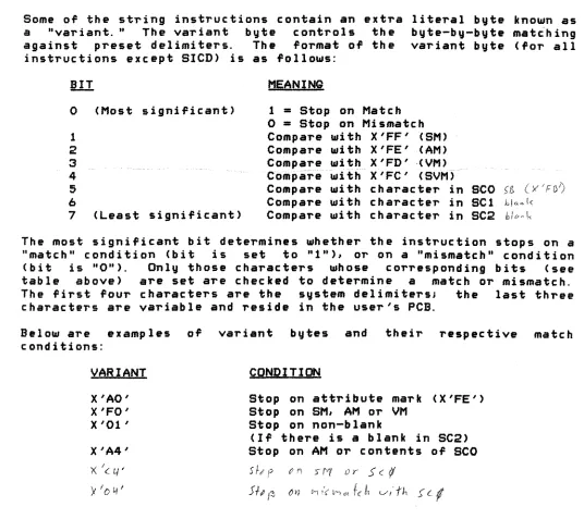
beginning of linked frame set is reached, a trap to the DEBUGGER is executed resulting in a FORWARD LINK ZERO abort message.Some of the string instructions contain an extra a "variant." The variant byte controls the against preset delimiters. The format of the
instructions except SICD) is as follows:
literal byte known as byte-by-byte matching variant byte (for all
o
1 2
3
4
5 6
7
(Most significant)
(Least significant)
MEANING
1
=
Stop on Matcho
=
Stop on Mismat~hCompare with X'FF' {SM) Compare with X'FE' (AM)
Compare wi thX'FD' "(VM)_~~~~~ _"~
··C·ompare--u,ft
h""X'
FC'-(S\lM)-Compare with character in SCO >~ (Y'FO?
Compare with character in SCl hl",~k
Compare with character in SC2 hit<4\<.
The most significant bit determines whether the instruction stops on a "match" condition (bit is set to "1"), or on a "mismatch" condition (bit is "Ott). Only those characters whose corresponding bits (see table above) are set
are
checked to determine a matchor
mismatch. The first four charactersare
the system delimiters; the last three charactersare
variable and reside in the user's PCB.Below are examples of conditions:
VARIANT
X'AO' X'FO' X'Ol'
X'A4'
x:
Ie 4'Y
I I:> 4'variant bytes and their respective match
CONDITION
Stop on attribute mark (X'FE') Stop on SM, AM
or
VMStop on non-blank
(If there is a blank in SC2) Stop on AM or contents of SCO
S 1-# f t' 1'1 S fY( () r S (
1/
Sf, J~ ()11 t-II'( M ... flIt v'"-/'h S'
cl
CHAPTER 2 MACHINE INSTRUCTIONS PAGE
[image:38.612.44.580.230.707.2]2.6.1 Scan to Delimiter (SID and SDD)
I
I
SID r,n
This instruction is used to find the end of a string, or to scan a
I
string to find the first or last occurrenc. of a character in thestring. The register (r) is incremented to point to the next
~~;~:~::I n~b~~:) V!~·i:~~~:::~(~;~ t~;e~·~;:n~·~ !·~::~u::!~t ~.~ e~k::t~~~o;~·
I
mi smatch c ond i ti on, as defined by the variant, is reached. Note thatthe this instruction will alter the position of the register by at
D
least one location.2.6.2 Scan to Delimiter and Count
u
SIDC r,n
This instruction scans a string from a register to a delimiter, and keep a count of the number of bytes scanned. The register is incremented to point to the next byte in storage, the lower-order 2 bytes of the accumulator (TO) are decremented one, and the byte addressed by the register is checked for a match or mismatch condition as defined by the literal variant byte. The process continues until a match condition is met, at which time the number of bytes scanned is the difference between the value of TO before and after the instruction. Note that this instruction will alter the position of the register by at least one location.
2.6.3 Scan to Count
2.6.4
SIT r
This instruction scans the register forward specified by the contents of TO. The re.gister is decremented until TO Teaches O.
the number of bytes is incremented and TO
This instruction is logically equivalent to the instruction "INC r,TO" however, the SIT instruction can be used to force usage of exception mode processing via XMODE (see SYSTEM SOFTWARE for XMODE usage) if it reaches the end of a linked ~ram, set. If TO is zero at the start of the instruction, it becomes a NO-QP and the register is not al teredo
Scan to count or delimiter
SITD T',n
This instruction combines the functions of the SIT and SID, in that the string is scanned until EITHER a match condition, as determined by the variant byte, is reached, OR the count in TO reaches zero. If the instruction terminates due to the match condtion being met, the difference in the ending and original values of TO gives the number of bytes scanned. If TO is zero at the start of the instruction, it becomes a NO-OP and the register is not altered.
CHAPTER 2 MACHINE INSTRUCTIONS
PAQE 26
Copyright 19~7 PICK SYSTEMS
D
n
n
n
o
n,
•n
u
n
r
I
I
2.6.5 Move String to Delimiter MIlD r,r,nI
I
I
I
o
n
n
2.6.6
This instruction is generally used to move a string ,ointed to by a register up to and including the delimiter marking the other end
0'
the string. Both registers are incremented by. one, and the byte pointed to by the 'irst register is moved to the location addressed bytnes.ccfnif~reglster~T1t e -~ Ifijt
.--maveif
1.---thEH' c·h e~ c·ii-cJ",or~ ··a~-~ma~tc~Ji~-~~using the variant byte. Th~ process
0'
incrementing, movin~ and checking continues until a match condition occurs. Note that this instruction will alter the position0'
the registers by at least one location.Move string to Delimiter and Count
MIIDC r,r,n
This instruction moves a string 'rom one register to the other up to a delimiter, and keeps a count
0'
the number0'
bytes scanned. Both registers are incremented by one, and the byte addressed by the 'irst is moved to the location pointed to bV the secondJ TO is decremented by one. The byte moved is the checked 'or a match, using the variant byte. This process is repeated until a match occurs. The number0'
bytes moved is the di"erence between the original value0'
TO and its value at the termination0'
the instruction. Note that this instruction will alter the position of the registers by at least one location.n
2.6.7 Move String to Counto
n
a
MIlT r,r
This instruction is used to move a string
0'
'ixed length. TO contains a byte count (up to 65,535) defining the number of bytes to be moved. If TO is zero when the instruction is executed, no operation is performed. Otherwise, the registers are incremented by one, the byte addressed by the first register is moved to the byte addressed by the second register, and TO is decremented by one. This process is repeated until TO reaches zero.o
2.6.8 Move String to Registern
n
r
r
MIIR: r,r
This instruction is used to move a string between the fi~st register and R15 to the location addressed by by the second register. The 'irst register is checked against R15, and if they are e~ual, the instruction ends. Otherwise, the registers are both incremented to pOint to the next byte in storage, and the byte pointed to by the 'irst register is moved to the bute pointed to by the second register. The first register is then checked against R15, and the cycle
0'
compare, increment, and move is repeated until the first register and R15 are e~ual. Note that if R15 is not ~orward0'
and in the same string as the first register, this instruction will not terminate.