Abstract— The hydrated silica frustules (exoskeletons) of diatomic algae are a prominent and fascinating example of Nature’s neat nanostructuration [1], achieved with low temperature and pressure processes, without the use of aggressive chemicals, and on the global scale. There is a growing interest in understanding and exploiting nature-like processes to improve the energy efficiency and sustainability of industrial fabrication. The present paper reports the results obtained during the fabrication of bulk porous silica ceramics by sintering and freeze-casting of diatomite earth slurries with the purpose of preserving and creating multi-scale porosity at the nano-, micro-, and macro-scale. In the course of fabrication processing, the samples were characterized by X-ray powder diffraction as a means of providing phase identification and observing phase transitions in silica. The slurry preparation was optimized to ensure consistent properties of the obtained hierarchically structured materials (diatomite earth poroids) for biomedical applications.
Index Terms— diatom frustules, diatomite earth, silica phase transitions, opal, cristobalite, quartz.
I. INTRODUCTION
iatoms are the unicellular species of algae that form a major biogenic source of silica on the planet. This Nature’s mechanism of silica storage represents a bottom-up self-assembly biomineralization process that created countless examples of intricately nanostructured diatom frustules composed predominantly of amorphous hydrated silica SiO2.(H2O)n (98% by volume) , also referred to as opal-AN [1].
Manuscript received January 21, 2019; revised January 30, 2019. This work was supported in part by the Royal Society, UK (IEC/R2/170223), EPSRC UK (EP/P005381/1), and the Russian Foundation for Basic Research (RFBR 18-44-920012).
Yuliya Kan is doctoral student with Skoltech - Skolkovo Institute of Science and Technology, Moscow 121205, Russia.
Alexei I. Salimon is Senior Research Engineer at the Hierarchically Structured Materials (HSM) lab, Skoltech Center for Energy Science at Technology (CEST), Skolkovo Institute of Science and Technology, Moscow 121205, Russia.
Philipp V. Sapozhnikov is Senior Researcher at P.P. Shirshov Institute of Oceanology, Russian Academy of Sciences, Moscow 117218, Russia.
Pavel Somov is with Tescan Russia, St.Petersburg 195220, Russia. Joris Everaerts is Post-Doctoral Fellow at the Multi-Beam Laboratory for Engineering Microscopy (MBLEM), Department of Engineering Science, University of Oxford, Parks Road, Oxford OX1 3PJ, UK.
Alexander M. Korsunsky is Head of the Multi-Beam Laboratory for Engineering Microscopy (MBLEM), and Professor of Engineering Science, Department of Engineering Science, University of Oxford, Parks Road, Oxford OX1 3PJ, UK (tel. +44 1865 273043, e-mail: [email protected]), and Visiting Professor, Hierarchically Structured Materials (HSM) lab, SM) lab, Skoltech Center for Energy Science at Technology (CEST), Skolkovo Institute of Science and Technology, Moscow 121205, Russia (email: [email protected]).
Due to the polymorphism of silica, the phase composition of diatomite earth changes during phase transitions induced by changes in temperature and pressure. Besides, diatomaceous earth may also contain impurities that undergo interaction with silica and may affect phase composition and colour. Judicious choice of processing conditions may allow the fabrication of bulk ceramic samples with controlled composition, structure, and strength properties, which in turn determine the range of possible applications of these products.
The unique nanoscale morphology of the diatomite frustules has been the subject of fascination to the researchers ever since the power of microscopic imaging allowed resolving the fine sub-micron detail of the various patterns of channels and protrusions found in them. Up to 65% of the shells is taken up by nanosized inner pores forming complex structures that are meso- to nano-porous and possess very large surface area. Whilst the precise functional purposes of these nanostructures remain the subject of active debate, it is clear that they affect the mechanical, nano-fluidic, electromagnetic, optical and plasmonic properties. Therefore, the preservation of these nanostructures during processing of diatomite powders (earth) into the resulting multi-porous bulk ceramics represents an interesting challenge, as it presents an interesting route towards Hierarchically Structured Materials (HSM), or smart composites.
Due to the small size and sub-micron structure of diatomite particles, objects and components derived from them can be consider to fall within the remit of nanotechnology. According to the studies reported in the literature, the diameter (greatest linear dimension) of individual diatomite frustules is in the range of 1–40 μm, and their thickness (smallest linear dimension) lies in the range 1.2–1.8 μm. This means that the agglomeration and joining of individual frustules into larger assemblies allows the creation of objects with micro-scale porosity. Finally, macro-scale processing, e.g. by 3D printing, allows the creation of hollow structures on the millimetre scale, thus achieving the objective of multi-scale hierarchical structuring.
These properties of diatomic powders make them highly interesting candidates for sophisticated design of biomimetic materials for electrical, engineering, and especially for biomedical manufacturing. A major advantage of using biogenically derived silica in the form of diatomaceous earth is the low cost and wide distribution.
The high porosity and high thermal stability suggest that diatomite-derived multi-porous bulk ceramics may be well-suited for the manufacture of filters and heat insulators. Thermoelectric industrialization demands the materials to be clean, cheap, and have high conversion efficiency. In the
On the Fabrication of Diatomite Earth-based
Ceramics with Multiscale Porosity
Yuliya Kan, Alexei I. Salimon, Philipp V. Sapozhnikov, Pavel A. Somov, Joris Everaerts, and Alexander M. Korsunsky, Member, IAENG
field of secondary energy storage, the development of new Li-ion battery electrodes also demands nanostructration to improve stability and efficiency. Silicon is the most popular low bandgap semiconductor, whilst silica-rich diatomite earth is a naturally abundant and non-toxic material that contains nanostructures that are otherwise difficult to achieve in device designs. In this context, there is a rising demand for new methods of treating silica to obtain nanostructured silicon for applications in the energy storage and thermoelectric fields [2].
Naturally assembled silica typically does not contain toxic heavy elements, such as Bi, Pb, Te, Se, or in any case can be obtained by directed growth of diatom populations in the field [REF WCE 2018 paper], or under even more controlled conditions, including mono-cultured ‘farming’. These considerations provide good reasons to investigate this source of silica for use in biomedical implementation. A number of studies revealed the bioactivity of silica and its impact on human tissues proliferation. Both in vitro and in vivo studies demonstrated an important role played by silica for bone cell adhesion. The nanostructuration of frustules provides inspiration for the development of biomaterials with improved osteoconductivity. It may further be possible to combine diatomic silica with hydroxyapatite to seek improvement in the properties and performance of scaffolds for prosthetic bone materials. Silica-derived biomaterial helps induce the precipitation of hydroxyapatite within bone tissue, which is promising development in hydroxyapatite deposition controlled reported in the literature [3]. The hierarchical distribution of pores in diatom frustules may be used to induce and guide osteointegration. Further studies investigated cytotoxicity of silica from diatomaceous earth [4],[5]. Bone scaffolds with advanced structure and properties may be made from silica-HAp combinations.
II. MATERIALS AND METHODS
A. SEM Imaging of Individual Diatom Frustules
Diatom frustules possess a tremendous variety of sizes and shapes, as illustrated in Fig.1.
Fig.1(f) shows a magnified detail of Fig.1(e), with complex pattern of nanostructured channels seen, that contains paired openings that may become connected subsurface, larger cross-shaped openings, and a central cleavage feature. Further detail of the nanostructured nature of silica frustules can be seen in Fig.2 at nanoscale resolution. Fig.2(a) shows a grill-like arrangement consisting of ~200 nm-thick walls with ~100nm-wide channels. The complex three-dimensional manner in which these channels interconnect can be perceived from the image. The precise nature of the brighter looking quasi-spherical nanoparticles seen at the surface has not been ascertained precisely at this stage.
Fig.2(b) is a further magnified image showing opening of several diameters between 200nm and down to ~50nm. In summary, a widely varied range of interesting morphologies can be observed in individual diatom frustules. Based on these observations, further effort was devoted at this stage of the project to the exploration of procedures for consolidation of diatomaceous silica powders.
With the key initial step in the creation of multi-scale porous ceramics based on diatomite earth silica, i.e. the
consideration of frustule morphology, accomplished as reported above, further work was directed at exploiting the large quantity of diatoms that can be obtained, as their exoskeletons show tremendous amount of variety, yet share certain common characteristics in function, composition, size, and structure.
A. Preparation of Specimens
Specimens of multi-scale porous bulk ceramics were made on the basis of commercial diatomite earth. Slurries were prepared using the mixture of diatomaceous earth and aqueous solution of carboxymethyl cellulose (CMC) with the mass ratio 45:55, respectively. Two types of solution were prepared, with 1% or 2% (by weight) of CMC in water. Samples were obtained by thorough mixing of diatomite earth powders (designated Dt1 and Dt2 below) with the phase composition: SiO2—86%, Al2O3—5,5%, Fe2O3—2,5%, MgO—0,78%, K2O –1,39%, Na2O— 0,22%) and 1-2 wt. % of CMC in the SPEX™
SamplePrep8000M Mixer/Mill (Stanmore, UK). The
resulting homogeneous slurries were loaded into a syringe and extruded to obtain miniature specimens.
The obtained samples were sintered to different temperatures in the muffle furnace Nabertherm Gmbh (Lilienthal, Germany) in order to assess the correlation between thermal treatment, phase composition, and other microstructural and mechanical property aspects, including porosity.
Fig. 3 shows that the starting diatomite powders already contained a mixture of some unbroken frustules, as for Dt2 in (b), with a large proportion of damaged shells, as shown for Dt1 in (a).
A. Size Distribution of the Diatomite
The two types of the diatomite earth powders denoted Dt1 and Dt2. Dt1 is commercial diatomite obtained by milling, whereas Dt2 is known as “garden diatomite”. The difference in between the commercial and garden diatomite is the milling process that modifies the size of particles: commercial diatomite finds applications in medicine and food industry that demand fine particle size.
Starting powders were characterized using SEM and laser particle sizing. The apparent difference in the morphology and size of particles seen in Fig. 3 was reflected in the difference in the size distribution which was measured using laser particle size analyzer Analysette 22 (Fritsch, Idar-Obserstein, Germany).
The mean particle diameter was equal to 4.75μm for commercial diatomite, whereas the garden diatomite was found to contain larger particles with the mean diameter of 26.63μm.
(a)
(b)
(c)
(d)
(e)
(f)
Fig.1. Illustrative SEM images of individual diatomite frustules at micro-scale resolution, showing a variety of sizes and shapes, with
(a)
(b)
Fig.2. Illustrative high magnification SEM images at nanoscale resolution showing further details of silica nanostructuration in
diatom frustules.
(a)
(b)
Fig.3. SEM image of the particles of diatomite earth samples Dt1 and Dt2, consisting (a) mostly of broken debris, with (b) some
underlying nanostructured pieces remaining.
Table I. Particle size distribution, commercial diatomite Dt1 Size Low
[µm]
Size Mid [µm]
Size High [µm]
Q3(x) [%]
0.000 0.566 1.132 10
1.132 1.466 1.800 20
1.800 2.135 2.470 30
2.470 2.831 3.191 40
3.191 3.590 3.989 50
3.989 4.459 4.929 60
4.929 5.509 6.089 70
6.089 6.867 7.646 80
7.646 8.943 10.240 90
Table II. Particle size distribution, garden diatomite Dt2 Size Low
[µm]
Size Mid [µm]
Size High [µm]
Q3(x) [%]
0.000 0.912 1.824 10
1.824 2.664 3.503 20
3.503 4.504 5.505 30
5.505 6.756 8.007 40
8.007 9.662 11.317 50
11.317 13.483 15.649 60
15.649 18.411 21.174 70
21.174 24.862 28.550 80
28.550 34.079 39.607 90
B. Sintering
Sample powders Dt1 and Dt2 were heated at the ramp rate of 5ᵒC/min to the target sintering temperature in the range 900ᵒC to 1200ᵒC and held for 2h before cooling.
Specimen color change was observed as a function of sintering temperature, from light yellow for lower temperatures to brownish red for the higher temperatures. Fig. 5 illustrates the color changes, including the untreated raw sample after extrusion to the sintered ones obtained with 100ᵒC steps in temperature between 900ᵒC and 1200ᵒC. This color change may be attributed to the migration of iron ions to the surface, or iron ions reacting with silica leading to andradite phase formation, as well as the possible conversion of different iron-bearing minerals to Fe2O3 [7]. Another possibility is the change in the predominant nanoscale dimension due to sintering.
Fig.5. Illustration of the color changes of diatomite samples prepared with 1wt% CMC and sintering to different temperatures.
III. RESULTS AND DISCUSSION
A. XRD quantitative phase analysis
The effect of thermal treatment was first characterized using quantitative phase analysis by X-ray powder diffraction using Bruker D8 ADVANCE with Cu Kα1 source with the wavelength = 1.54Å. DIFFRAC.EVA software was used.
[image:5.595.307.546.358.624.2][image:5.595.59.281.569.678.2]
Fig. 6. The sintering temperature evolution of XRD patterns of samples produced from diatomite slurry with 1wt% of CMC.
Fig. 7. The sintering temperature evolution of XRD patterns of samples produced from diatomite slurry with 2wt% of CMC.
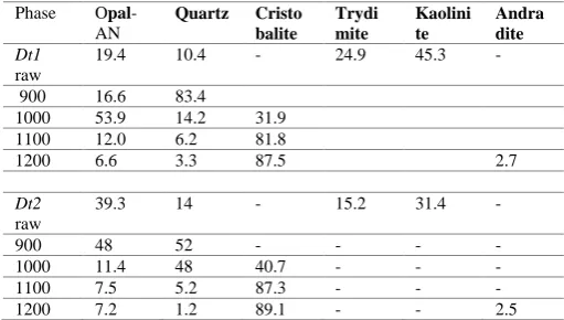
Table III represents the results of quantitative analysis of the polymorphs of SiO2 comprising quartz, cristobalite, and other known forms.
Table III. The results of quantitative phase distribution analysis of silica polymorphs (vol %) obtained by XRD in
raw (non-sintered) and samples sintered at different temperatures (in ˚C).
Phase Opal -AN Quartz Cristo balite Trydi mite Kaolini te Andra dite Dt1 raw
19.4 10.4 - 24.9 45.3 -
900 16.6 83.4
1000 53.9 14.2 31.9
1100 12.0 6.2 81.8
1200 6.6 3.3 87.5 2.7
Dt2
raw
39.3 14 - 15.2 31.4 -
900 48 52 - - - -
1000 11.4 48 40.7 - - -
1100 7.5 5.2 87.3 - - -
1200 7.2 1.2 89.1 - - 2.5
The results reveal that diatomite sintered at 900ᵒC contains quartz and amorphous phases, the latter being responsible for the appearance of the broad peak. No peaks corresponding to cristobalite can be seen, indicating that high-temperature phase transition has not begun.
Significant compositional change was observed after sintering at 1100ᵒC. shape change of diatomite shells also noted after sintering in this temperature range as confirmed by SEM imaging (see next section). These observations are in agreement with the previously reported phase transition of amorphous silica to the cristobalite at 1100ᵒC [8]. Comparison of Fig.6 and Fig.7 demonstrates that the variation of CMC solvent concentration does not affect the resulting phase compostion. Further sintering at 1200ᵒC produces samples containing the cristobalite phase, whereas the peaks belonging to quartz are diminished and eventually disappear. Samples Dt1 and Dt2 differing only by the content of CMC in the aqueous solution show very similar characteristics of X-ray diffraction patterns, with similar character of phase distribution, as also seen from Table III. After heating and sintering at 1100ᵒC and 1200ᵒC, a highly crystalline state appears dominated by cristobalite. The peaks of quartz and amorphous opal phase previously found in the non-sintered and low-temperature sintered samples are no longer present.
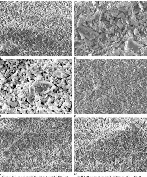
B. SEM analysis
The microstructure and morphology of sintered samples was examined by scanning electron microscopy using JSM-6480LV (JEOL, Tokyo, Japan).
The presence of recognizable diatomite frustules is visibly decreased as the heating temperature increases. The destruction of diatomite shells was noted after sintering at temperatures from 1100ᵒC. SEM images show negligible number of particles preserving the initial fine structure of diatomite frustules.
The series of SEM images shown in Fig.8 and Fig.9 below provide the illustration of the morphological changes that
composition changes reported previously from the analysis of X-ray diffraction data. The images were taken at different magnifications (2000X and 5000X) in order to allow multi-scale perception of the features present in the sintered samples following prescribed heat treatment. It is apparent that multi-scale porosity is present in the samples. However, recourse to laser particle sizing employed previously for powders is no longer possible in this case. This means that other methods must be used, such as quantitative image analysis of SEM micrographs. Whilst this is possible, there are further challenges in the way of implementing this approach, associated with the fact that only sample surface obtained by fracturing is visible in the image. This raises questions concerning whether this image is indeed representative of the bulk of the sintered ceramic pieces studied.
An alternative non-destructive method that is capable of providing access to 3D volume information is the use of X-ray tomography. The current limit of spatial resolution extends down to a few tens of nanometers, although attaining this resolution places limitations on the field of view, i.e. the size of volume examined. A good combination of experimental conditions that offers relatively straightforward data collection and analysis and captures sufficiently large representative volumes is the use of synchrotron X-ray tomography with the nominal pixel size of 330nm.
Synchrotron X-ray tomography data collection and analysis were carried out for this project at beamline I13, Diamond Light Source (Harwell, Oxford, UK). An illustrative image of the transverse ‘slice’ obtained is shown in Fig.10. It is apparent that, whilst the inhomogeneous and porous structure of the bulk ceramic is visible, the detail of nano-scale porosity is not immediately accessible.
It is clear from the results presented so far that complete understanding of the structure and properties of complex, multi-level, hierarchically porous structure of sintered silica ceramics derived from diatomic earth requires the combination of different imaging and characterization techniques. In particular, the combined and correlative use of SEM and X-ray tomography imaging needs to be developed further to enable quantification of pore structure and shape, as well as their size distribution as a function of processing parameters employed in the preparation.
Furthermore, careful selection of the sintering temperature and duration needs to be pursued in view of the specific application of silica poroids. For example, developing sufficient strength may require the use of higher sintering temperatures, whilst preserving the nanostructured porosity inherited from diatomic frustules may only be achievable at lower temperatures. These requirements are disparate, but may turn out not to be conflicting, i.e. judicious choice of heat treatment temperature, duration of exposure, binder and atmosphere may allow attaining specific properties and structure.
IV. CONCLUSION
The preliminary study reported in the present paper has revealed some details of the use of biogenic silica derived from diatomite frustules for obtaining multi-scale porous ceramics.
(a)
(b)
[image:7.595.49.557.46.657.2](c)
Fig. 8. SEM images of sample Dt1 sintered at (a) T=900ᵒC, (b) T=1000ᵒC, and (c) (a) T=1100ᵒC.
(a)
(b)
(c)
ACKNOWLEDGMENT
AMK wishes to acknowledge the provision of beamtime allocation MT21312 for access to I13 at DLS, Harwell Oxford, UK. The authors acknowledge funding from Royal Society, UK (IEC/R2/170223), EPSRC UK (EP/P005381/1), and the Russian Foundation for Basic Research (18-33-20132).
REFERENCES
[1] A.M. Korsunsky, P. Sapozhnikov, J. Everaerts, A.I. Salimon, “Nature’s neat nanostructuration: fascinating frustules of diatomic algae”, Materials Today, 22C, 169-170, 2019.
[2] C. Mansilla, M. H. Novais, E. Faber, D. Martínez-Martínez, and J. T. De Hosson, “On the 3D reconstruction of diatom frustules: a novel method, applications, and limitations,” J. Appl. Phycol., 28, 1097– 1110, 2016.
[3] P.-A. Zong et al., “Converting natural diatomite into nanoporous silicon for eco-friendly thermoelectric energy conversion,” Mater. Des., 154, 246-253, 2018.
[4] S. Tamburaci and F. Tihminlioglu, “Biosilica incorporated 3D porous scaffolds for bone tissue engineering applications,” Mater. Sci. Eng. C, 91, 274-91, 2018.
[5] M. López-Álvarez et al., “Silicon-hydroxyapatite bioactive coatings (Si-HA) from diatomaceous earth and silica. Study of adhesion and proliferation of osteoblast-like cells,” J. Mater. Sci. Mater. Med.,. 20, 1131–1136, 2009.
[6] N. Nassif and J. Livage, “From diatoms to silica-based biohybrids,”
Chem. Soc. Rev., 40, 849–859, 2011.
[7] S. S. Ibrahim and A. Q. Selim, “Producing a micro-porous diatomite by a simple classification-calcination process,” J. ORE Dress., 12, 24–32, 2010.
[8] P. Yuan et al., “Surface silylation of mesoporous/macroporous diatomite (diatomaceous earth) and its function in Cu(II) adsorption: The effects of heating pretreatment,” Microporous Mesoporous Mater., 170, 9–19, 2013.