'@
~
a.
~ ~
lOGiHCH
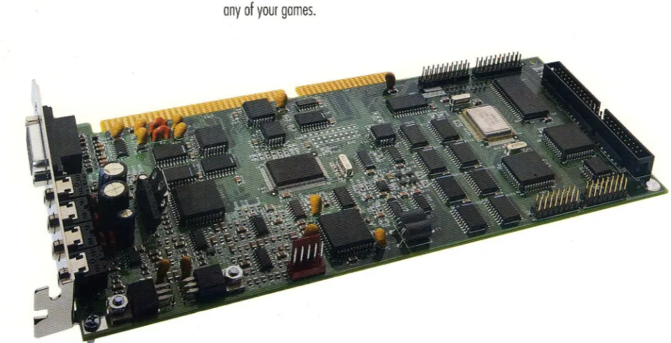
Advanced technology
for the most real istic
sound available
For IBM Compatibles
Breakthrough wave table synthesis - coupled
with state-of-the-art 16-bit stereo - brings you
a whole new standard in true-to-life sound
.
Now you can enhance your experience of
today's popular games and music with a
totally realistic new sound dimension
.
Leading
edge wave table technology makes the music
in your games and multimedia applications
actually sound like real instruments,
i
nstead
of computer-generated sounds
.
'·
Wave
[image:1.600.64.548.494.741.2]Best of all thanks to SoundMan Wave's unique
,
MIDI interpreter, you can hear superior wave
table quality right now - in many of today's
hottest games, including X-Wing, 7th Guest
and Space Quest 5
.
State-of-the-art 16-bit quality for
recording and playback
The music,
narra-tion and effects you record with Sound Man
Wave will also have the professional quality of
your home stereo CDs. SoundMan Wave
actual-ly uses the same 16-bit 44
.
1 kHz sampling
technology used on digitally mastered CDs.
No need to worry about becoming
obsolete
If you want to move up to
surround sound in the future .
..
or add reverb
or chorus effects to your music, simply add
Logitech's DSP chip upgrode to your SoundMan
Wave
.
1 00% Sound Blaster, Sound Blaster
Pro, and AdLib compatible
Because
SoundMan Wave includes a Yamaha OPL 4 chip
(not an FM emulation used with some boards),
you are guaranteed it will work perfectly with
any of your games
.
Popular SCSI CD-ROM interface
If you're adding a single ar double speed
CD-ROM drive, Sound Man Wave's widely
accept-ed SCSI interface gives you more options than
any other CD-ROM interface
.
Hardware-based audio compression
standards
Sound Man Wave's hardware
compression not only meets or exceeds the
accepted IMA compression/decompression
standard, it also supports ADPCM and
CCln
A-Law and u-Law - for dramatic disk space
savings without slOWing down your computer.
Easy installation
SoundMan Wave's
sound-enhanced, jumperless installation
program makes it the easiest to install.
Includes valuable bonus
software
MCS MusicRack™ from Animotion®
Control
all Windows 3.1 sound features
from
a
convenient window that looks and works
like a home stereo system. The
intuitive
MCS
MusicRack interrace makes it all easy. The
most complete PC stereo software available,
it includes: mixing console; CD
software
player for CD-ROM drives with audio playback
copabilities; digital recorder for recording and
editing WAY files; MIDI player.
Recording Session® from Midisoft®
Record, edit and playback MIDI music with
this powerrul, easy-to-use program. It displays
your musical files or perrormance as standard
music notation in real time during recording
and playback.
BeSTspeech® ReadOut™ from
Berkeley Speech Technologies
Use this
high quality text-to-speech utility to read text
from OLE applications such as word
process-ing, electronic mail and presentation software.
Used with OLE spreadsheets, it makes double
checking figures easy.
SoundMan Annotator™ from
Voyetra™
Annotate messages into any
Windows OLE application in a snap.
Icon Hear-lt™ Lite from Moon
ValleYTM
Personalize your Windows desktop
by replacing regular icons with these
outra-geous icons and sound effects.
DOS software and driver
Record, play
back and mix sound in DOS. The recording
utility offers high-quality recording. The
play-back utility provides superior output quality.
The mixer blends CD-audio, synthesized audio,
"leon Heer-H Ute
[II Options ...
Help ... About Icon Hear-It. .. I Remove Icon Hear-It
digital audio,
external
line-in, and microphone.
It also controls bass,
treble
and volume.
SoundMan Wave Specifications
Wave
Table
Synthesis
Yamaha
OPL-4
stereo synthesis with 44 voices
offering
both
FM and
wave
table
synthesis
Supports
16
MIDI channels
2MB
of
wave
table
samples
in ROM on board
128 General
MIDI
instruments
Advanced
MIDI
interpreter for General
MIDIjMPU-401
inte~ace
C~-Quality
Sound
16·bit and 8-bit
stereo
recording and playback
Sampling/playback
rate from 4kHz to 44.1 kHz
Advanced Hardware Features
Dynamic filtering
Hardware compression techniques include IMA, ADPCM
and
CCln
Maw and u·Law
SCSI CD·ROM
inte~ace(cable
kit available
separately)
High Performance 16-bit OMA
Software
selectable
DMA and IRQ
settings
for optimal
and easy installation
Compatibility
100
%
Sound Blaster, Sound Blaster Pro and AdLib
compatible
General
MIDI
compatibility through MPU·401
inte~aceWindows 3.1 and DOS 3.3 or higher compatible
MPC
(1
and 2) and MPU-401 (UART) compatible
Input/Output
5·channel stereo mixer
Stereo amplifier outputting 6
watts
per channel
Line out connector for best
signal/noise
ratio
Microphone and line-in inputs for recording from
external
sources
Input jacks accept CD·audio input from internal and
external CD-ROM drives (cables available separately)
IBM-standard joystick port for 1 or 2 players/MIDI
inte~ace
(optional MIDI
kit available
separately)
Software
_ Animotion MCS MusicRack
_ DOS driver
_ Midisoft Recording Session
_ DOS mixer
_ Berkeley Speech Technologies _ DOS recording
BeSTspeech ReadOut
utilities
_ Voyetra SoundMan Annotator _ DOS playback
_ Moon Valley Icon Hear·lt Lite
utility
_ Windows 3
.
1 driver
System Requirements
IBM
PC compatibles with 386 processor or
above
DOS
3.3 or above, or Windows 3.1 or
higher
640KB RAM (4MB
recommended for
Windows
use)
Open slot
for
16-bit
inte~aceboard
One
3.5"
high
density disk drive
Speakers or
headphones for
output
Microphone or
CD·player for input
Logitech or
compatible
mouse
for Windows
use
Warranty
SoundMan
Wave is backed by Logitech's three·year
war
-ranty,
with
limited lifetime
warranty afterward.
Product Support
Call Logitech 7 days a
week
for technical
support,
or
use
our
24·hour electronic
bulletin board
.
Take
advantage of
the FaxBack line to receive product information by return
fax. There is also a Logitech Forum on CompuServe
.
Product Support Hotline:
(510)
795·8100
Electronic Bulletin Board:
(510)
795·0408
FaxBack Line
:
(800)
245·0000
Satisfaction Guarantee
Logitech
wants
you to be pe~ectly happy
with your
SoundMan Wave Sound Board. If you are not completely
satisfied,
return it to your reseller
within
60 days
with
the complete contents of the package and proof of pur·
chase for a full refund
.
(Full
details inside the package.)
Sales Information and Support
Call us for the dealer nearest you, or
sales/dealer
information during normal business hours.
In U.S.A. and Canada:
(800) 231·7717
'C
~
a.
~ ~
lOGiHCH
The Sensewore" Company
Logitech Inc.
6505 Kaiser Dr.
Fremont, CA 94555
(510)
795-8500
© 1993 logitech. All rights reserved. logitech and SoundMan are trademarks of logitech. All other trademarks are the property of their respective owners. OSR97A 1193
~
-lOO;TICH
SoundMan Wave
Technical Reference
Version 1.0
Logitech Inc.
6505 Kaiser Drive, Fremont, CA 94555 © 1994 Logitech, Inc. All Rights Reserved. Published 1994
Printed in the United States of America
Logitcch, Inc. ("Logitech") has made eve'Y effort to ensure the accuracy of this manual. However, Logitcch makes no warranties with respect to this documenmtion and disclaims any unphed warranties of merchantability and fitness for a particular pwpose. The,inf'lnnation m this document IS subject to change WlthOut noUce. Logitech assumes no responsibibty for ally errors that may appear in this document. .
Tlus editlOn appbes to LOgltech SoundMan Wave, verslOn 1.0. Document.
Released
T radornarks
March 1994
LOgltech, SoundMan, and the LOgltcch logo are trademarks ofLogitech, Inc.
Table of Contents
Introduction ...•... 1
Purpose ... 1
Scope ... 1
Document Organization ... 1
Technical
Ove~iew...•.
3
Summary ... 3
Card Layout. ... 4
Hardware ... 4
Finnware ... 5
Software ... 5
Options ... 6
Architecture ... 7
Functional Block Diagram ... 7
SCSI/CD-ROM Controller ... 7
FM+Wave Table Synthesizer ... 8
CODECIDigital Audio ... 8
MIDI Microprocessor ... 8
Bus Interface Logic ... 9
Mixer ... 10
Programming ... 11
Finding Board Configuration ... 11
Detecting and Resetting the Board ... 13
Relocatable Base Address ... 14
SCSI Controller Registers ... 15
Microprocessor Registers ... 15
Control Register ... 16
Joystick Registers ... 17
OPL2/0PL3/0PL4 Synthesizer ... 18
Programming the MVD 1216 ... 18
Programming Digital Audio (pCM) Transfers ... 20
Setting the Sampling Rate ... 22
Controlling the Speaker ... 22
Setting the DMA transfer length ... 22
Pausing and Finishing DMA ... 22
Selecting 8/16-bit and Mono/Stereo ... 23
'Starting
a
PCM Transrer ... ; ... :., ... _ ... ; .... ~ .. H ••••••• ·.~23 .. ".,:"~~ Selecting DMA and IRQ Channels ... 24Reading the DMA and IRQ Settings ... 25
Mixer ... 26
General MIDI ... 31
External Interfaces ... 37
Speaker Output (Speaker Jack) ... 37
Stereo Line Output (LINE OUT Jack) ... 37
Stereo Line Input (IN Jack) ... 37
Microphone Input (MIC jack) ... 38
Game (Joystick) Port ... 38
MIDI Port ... 38
CD Audio Connector (J2) ... 39
SCSI Connector ... 39
Board Specifications ... 39
Technical Notes ... 41
Make MIDI (MPU-401) Configurable ... .41
Separate Digital Audio from Music Synthesis ... .41
Is SoundMan Wave Compatible with (any) ProAudio Spectrum? ... .41
Logitech Developer Support ... 43
Customer Service, Technical Support or Developer Relations? ... .43
. Sending a Fax to Logitech Developer Relations ... .43
Internet E-mail to Logitech Developer Relations ... .43
Logitech FaxBack Service ... 44
. Logitech On-Line ... 44
Support Phone Numbers and Addresses Worldwide ... .45
Ref eren ces ... 47
1
Introduction
Purpose
Scope
This document ·is a reference'to the Logitech SoundMan ·Wave sound board, for _ .. _-. -o . 0 •
programmers and developers. It- is intended to provide developers with all of the
information they need to fully support the Logitech SoundMan Wave sound board in their products.
This document describes the primary programmatic interfaces ofthe SoundMan Wave sound board, including the hardware (register level) interface. The SoundMan Wave sound . \'. board has extensive compatibility-with existing industry standards - this docume!1t does not
reproduce those standards in their entirety, but provides precise references and sources for those standards.
The external electrical and electronic interfaces.ofthe SoundMan'Wave sound board are also described in this document.
DocumentOrganiza#on
This document is composed of the following sections:
Section 1: Introduction
Section 2: Technical Overview
Section 3: Architecture
Section 4: Programming
Section 5: External Interfaces
Section 6: Technical Notes
Appendix A: Logitech Developer Support
Appendix B: References
3124/94 SoundMan Wave Technical Reference Revision: 1.0
2
Technical Overview
Summary
3/24/94
• Full SoundBlaster compatibility
• Yamaha YMF278 (OPL4) Wave Table synthesizer
• Register-compatible with earlier generation OPL3 and OPL2 FM synthesizers
• Can simultaneously produce a total of 44 voices (20 FM
+
24 wave table) • Wave synthesizer generates up to 512 tones• 2MB of wave table (OPL4 patch) ROM
• MIDI MPU-401 transmit and receive interface
• General MIDI via MPU-401 for Roland Sound Canvas compatibility
• Supports 16-bit/8-bit stereo or mono digital audio at rates up to 44. 1KHz
• Capable of 16-to-8 or 8-to-16 bit file conversion
• Supports stereo to mono file conversion
• A-law, u-Iaw, IMA ADPCM,' and Sound Blaster Compression/Decompression • 5-channel stereo mixer
• Software programmable Base Address, IRQ and DMA channels
• External MIDI port (with optional adapter)
• SCSI interface for internal and external CD-ROM drives (with optional kits)
• CD-Audio connector on card, for audio input from CD-ROM drives
• Games-compatible joystick interface
• Mini-jacks for Line In, Line Out, Speaker Out and Microphone on back panel
• Microphone Pre-Amp
Section 2
Card Layout
Hardware
SCSI CDR OM CONNECTOR
MICltOPltOCESSOlt
~
: SCSI : CNTRk..
,--- ---~
---~:
.'
FM/WAVE ::
.'
SYNTH. ::
.:
.. - --- --- -- --_I _ _ _ _
CD AUDIO
CONNECTOR~
---: ---_Q_-
• ICODEC:: 1 . . _ _ _ _ _ _ _ ANALOG ,
______ : : - - - : : AUDIO ---: :MIXER:: en
~j=:===)~---~--~
BUS INTERF ACE : ~~ ;~--:
LOGIC : :STIcx:
_ _______________ .J I I
A T BUS CONNECT OR
MIC INPUT
EXT OUTPUT
SPKR OUTPUT
EXT. INPUT MIDI/
JOYSTr:K ffiRT
SoundMan Wave is an AT Bus adapter card which supports synthesized music, and digital audio recording/playback electronics. The music is generated by use ofFM and Wave Table .. synthesizers_ The FM synthesizer can support OPL2/0PL3 functions, and it provides
ADLib/SoundBlaster compatible hardware. The Wave Table synthesizer is based on the Yamaha OPL4 (YMF278), and it is interfaced through the MIDI UART. The common MIDI commands are used to generate general MIDI sounds. The Digital Audio section implements both 8-bit and 16-bit PCM record and playback in stereo or mono format. The digital audio section can provide 2: 1,3:1, and 4: 1 compression/decompression for PCM files in both mono and stereo samples.
Revision: 1.0 Page 4
A mixer circuit is provided to combine the outputs of the FM synthesizer, the Wave Table synthesizers, the Digital Audio system, a Microphone, a CD player, and an external audio source. The mixer output is amplified for external speaker connections. A SCSI bus controller supports CD ROM interface for internal and external drives. Both MIDI and joystick interface are available on an external 15-pin DSUB connector.
In the future, Logitech may support the addition of RAM to the SoundMan Wave via a daughter-board, allowing custom patches to be downloaded to the synthesizer.
Firmware
Software
3124/94
Technical Overview
A MIDI interpreter resides in RAM on the board It will be downloaded from the DOS ·drivers to make sure that it is present when needed. . ,.
The MIDI interpreter may include a number offeatures to enhance the rendering of
instruments by the OPL4 chip. For this reason, the firmware may be revised and distributed with new updates of the drivers.
Microsoft Windows 3.1:
DOS:
WAVE driver 8 and 16 bit, mono and stereo record and playback.
MID driver since the board handles General MIDI via on-board firmware, the MID driver is a relatively generic MPU-40 1 driver.
:MIXER driver
MCS MusicRack for Windows Midisoft Recording Session Annotator
BeSTspeech ReadOut
SMWSET.SYS SETUP
SMWVOL.EXE MPLAYEXE WPLAYEXE RECORD.EXE
- hardware initialization driver, not required after boot-up. - setup utility
- TSR for hot-key volume control.
- command line MIDI player, uses MPU-40 1 interface. - command line W A V player.
- command line WA V recorder.
MSCDEX and low-level SCSI driver - not shipped with SoundMan Wave, but included with separate CD-ROM accessory kit available from Logitech.
Section 2
Options
Internal CD·ROM Kit
Includes ribbon cable, audio cable, CD-ROM drivers.
External CD·ROM Kit
Includes dummy board with SCSI and audio connectors, internal ribbon cable, internal audio cable, . external CD-ROM cable, 2 external audio cables, and CD-ROM drivers.
SoundMan MIDI Adapter
Revision: 1.0 Page 6
Optional adapter available from Logitech. The adapter provides input opto~isolation, outpuL~ :; line drivers, and the physical MIDI connectors: DIN-5-pin (180 degree)·female .. The UART .. , ' I
is on the SoundMan Wave board.
3
Architecture
Functional Block
Diagram
Synti'tesizerMIDI Dri •• r
---, ,
: M, ,
cr.,r.uSlor:
,---Bus IIF Logic
.---;
: MVD1216 :
: '
---OPL4
FM IWave Table SyntneS1zen
$YNTH. OUT
~~~-~~~~e~l
I
11'
ou
~
- - - _ - - ___ - -' 1 .. 4tt---tI>I ... L_C_O_D_EC--.JI"'f--,-1 . MIXR OUT MIXERSCSI Control1er
SoundMan Wave
Sl'XR DRIVE
SCSI/CO-ROM Controller
3/24/94
The SCSI controller is a Zilog Z5380, an 8-bit single-chip controller that meets MPC requirements. The on-board SCSI connector is a standard 50-pin header.
SoundMan Wave has been tested successfully with many different double-speed drives - at the time of publication there is reportedly a 'glitch' with Hitachi and Texel drives, but a driver fix is expected soon. Contact Logitech Product Support for information - see Appendix A.
Logitech recommends NOT programming directly to the SCSI controller on-board. Use DOS/MSCDEX services, or low-level SCSI services instead. Contact Logitech Developer Support (see Appendix A) if you require information
on
these API's.Section 3
FM+ Wave Table Synthesizer
The FMlWave Table-synthesizer consists ofYamaha's"YMF218 (OPL4 )-cbip, .. 2Mbytes 'Of '
ROM for wave patches, and the YAC513 D/A converter. The FM synthesizer produces up to 20 voices, and it is register compatible with previous generation OPL2 and OPL3 synthesizers. The wave table synthesizer produces up to 24 voices. The 2Mbyte ROM section provides sound patches to support the general MIDI set.
Both synthesizers can be played simultaneously to produce up to 44 voices. The output of the FM synthesizer and the wave table synthesizer are digitally mixed to produce a single 16-bit stereo output. The YAC513 is utilized to convert the synthesizer outputs to stereo analog output.
CODEe/Digital Audio
The CODEC is the core of the Digital Audio subsystem. The CODEC section includes a' '-'.-MediaVision MVA416 16-bit CODEC, a PLL, an Input Buffer, and an Output Buffer. The 16-bit CODEC converts stereo analog signals to PCM digital data and vice versa. During PCM recording, the CODEC generates 16-bit PCM,samples for both the left and, ;the right inputs. During PCM playback, the CODEC converts the stereo 16-bit data points to analog.
The recording and playback data rate can be adjusted to 11KHz, 22KHz, and 44. 1KHz - ": -speeds. The PLL circuit generates the Sample Rate clock for1he CODEC. The Input Buffer ' "
and the Output Buffer interface the CODEC to the Mixer section.
MIDI Microprocessor
Revision: 1.0 Page 8
An Intel 8031 microprocessor unit provides control for the OPL4 synthesizer through the MIDI bus. The microprocessor monitors data transactions on the MIDI bus, and it responds to MIDI commands that are sent to the on-board synthesizer. The microprocessor section includes an 8K byte SRAM, three AT Bus interface registers, and an OPL4 bus multiplexer. The AT bus registers are used for downloading the microprocessor's,code at power up, and the OPL4 bus multiplexer is utilized for switching the synthesizer control lines between the microprocessor and the AT bus.
Architecture
Bus Interface logic
Mixer
3/24/94
The Bus Interface Logic ·provides address decoding and signal buffering. A Media Vision .. ' 1216 chip provides: a Sound Blaster 'compatible digital audio· interface, an MPU-401 MIDI. port, a game compatible joystick port, an OPL4 synthesizer interface, and programmable IRQ and DMA lines. Other Programmable Logic Arrays (PALs) interface the MIDI Microprocessor and the SCSI controller to the AT bus.
A Sierra Semiconductor SC18076 provides mixing functions. The Mixer controls the gain of individual sound sources, and combines all sources to produce two stereo outputs. The . :mixer has five "stereo· soun:esioSyntitesizer, -digital audio (CODEC); CD·ftudio,extemal,
audio (Line In), and microphone (Mic). One mixer output (playback) goes to the speaker output amplifier (Line Out), the other goes to the Digital Audio subsytem for digital recording.
t 1
Rl
t 2 R2
t 3 R3
t , R'
t S RS
10 Channel AUenuator
+-__
--1-. MixingNode
Playback
...--'" Volume
Control
Record
+-...
---1 .. Volume'---' Control
Digital Control Registers
8-bit I/F
Mixer Subsystem Diagram
Supplies
&
BIAS
4
Programming
Finding Board Configuration
3/24/94
Environment Variables
For DOS applications, the SoundMan Wave installation and configuration software sets two environment strings:
SET BLASTER = Axxx Dd Ii Tn Hh Pxxx
SET LSOUND = directory containing SoundMan software
where:
Axxx SoundBlaster base address (hex).
Dd SoundBlaster DMA channel, for 8-bit DMA.
Ii Sound Blaster IRQ,1JSed-for-digital audio/PCM interrupts. Tn SoundBlaster version number.
Hh DMA channel for 16-bit audio (if not specified, same as 8-bit DMA). Pxxx MPU-401 base address (hex).
There is at least one space between configuration parameters - your code should ignore any parameter that begins with a letter you do not recognize or care about. The parameters are not guaranteed to be in the order given above. The default values are:
A220 Dl 17 Tl H5 P330
Section 4
SOUNDMAN.lNI Parameter File
Revision: 1.0 Page 12
Other configuration information is stored in the file SOUNDMAN.INI - follow the LSOUND environment variable. The format of SOUNDMAN.INI is as follows:
[Global]
Type
=
SMW[WAVE]
Address
=
240IRQ
=
7DMA8 = 1
DMA16 = 5
[MIDI]
board type: SoundMan Wave
SoundBlaster base address SoundBlaster IRQ
SoundBlaster DMA channel
16-bit audio DMA channel
Firmware
=
TSUNAMI.BIN Address=
330General MIDI interpreter code MPU-401 base address
IRQ
=
2 [MIXER] WAVE=
100 MIDI=
100 CDROM=
100 MIC=
100 IN=
100 OUT=
100 Treble=
50 Bass = 50MPU-401 IRQ
Mixer levels
We strongly recommend that developers take board configuration information from the environment variables and files described above, and avoid the practice of scanning hardware registers to locate and recognize equipment.
Programming
Detecting and Resetting the Board
3/24/94
Address (Hex) Reltister Access
SBA+06 Reset Register W
SBA+OA Relld Data Port - PCM Data Register (8-bit) R
SBA+OB PCM Data Register (l6-bit) R
SBA+OC Status Register R
SBA+OC Command Register W
SBA+OE Data Available Register R
Standard procedure recommended by Creative Labs and Media Vision, for detecting and resetting a Sound Blaster compatible board:
. '1: WriteOlh to the.Reset Register at SBA(Sound Blaster register base address) +~_ -;"'/ .
Held for 3 its, this forces a hardware reset
2. Wait 3 Its (microseconds).
A good way to guarantee a3 Its delay is to issue three 110 reads from the· Reset Register address (it isn't a readable register, so it doesn't matter what comes back.) 110 reads will slow the CPU to an effective 8MHz, no matter how fast it normally runs.
3. Write OOh to the Reset Register, releasing the reset state.
4. Read the Data Available Register (at SBA+OEh) until bit 7 is 1.
This bit is the Data Available bit, and it signals that a byte is ready to be read.
If no data is available after 'about' 100 its, you can assume that either (a) there is no SoundMan Wave board at that address or (b) the board is failing to reset i.e. there is a hardware failure. The sample code from Creative Labs tests the Data Available Register 65536 times before giving up ...
5. Read from the Read Data Port (at SBA+OAh).
The returned byte will be OAAb to indicate successful board reset Treat a returned value other than OAAb as a 'no response' failure in step 4 above.
Section 4
Relocatable Base Address
Revision: 1.0 Page 14
SoundMan Wave provides two programmable Base Addresses (SBA & BAM) for its I/O register map.
SBA is the base address for what might be called the 'SoundBlaster' registers, including the OPL3 synthesizer.
BAM is the base address for the MPU-40 1, SCSI controller, 8031 MIDI microprocessor, and the Control register.
In the tables on the' following pages, register addresses that are relative toone of these 'base ."., ' addresses are written in the form SBA +xx or BAM+xx,
These base addresses are defined by programming the Base Address Con:(iguratiQn Register. at location 201h, The BACR is cleared after power up (BACR=OO). This disables all I/O accesses to this board except write accesses to location 201h. The BACR can be
programmed by writing three consecutive bytes to location 201h, The first two bytes must be AFh followed by 50h, the third byte should be configured according to the tables below.
I~
I~ I~
I
!wAlI
~AO
OPAr2:11 Base Address l(SBA)
00 -
disabled-01 220h
10 240h
11 260h
MPA[2:11 Base Address 2 (BAM)
00 -
disabled-01 310h
10 320h
11 330h
Programming
SCSI Controller Registers
Address (Hex) Re2ister Access
BAM+lOh-17h Zilog 5380 Controller RIW
BAM+18h Zilog 5380 DACK Reg. RIW
BAM+19h Zilog 5380 DRQ Reg. R
BAM+IAh Zilog 5380 DACKJEOP Reg. RIW
BAM+lBh Zilog 5380 RESET Reg. W
No programming information provided in this release.
Microprocessor Registers
3/24/94
Address (Hex) Register Access
BAM+04 :MPData RIW
BAM+05 :MP Lower Address W
BAM+06 :MP Upper Address W
MP Data Register
This 8-bit data register provides access to the 8K byte RAM area of the 8031
microprocessor. Writing to, or reading from this register writes or reads the location in 8031 RAM determined by the :MP Lower Address and :MP Upper Address registers. :MP Data Register accesses are denied while the 8031 microprocessor is active. The processor must be in reset state before the RAM area can be accessed - see Control Register.
MP Lower Address Register, MP Upper Address Register
These two registers are concatenated to form the address in 8031 RAM accessed by the :MP Data Register. The address is formed by taking the low 5 bits of:MP Upper Address, and appending the 8 bits of:MP Lower Address.
The upper 3 bits of:MP Upper Address are reserved, and must be zero.
Section 4
Control Register
Revision: 1.0 Page 16
'sterData
This registercontrols"the reset'state of the 8031 micro, -and selects the IRQ channels for the SCSI controller and OPL4 synthesizer. It is cleared to 0 on system reset.
This register must be accessed by Read-Modify-Write so that any initialization software will not interfere with the microprocessor driver program, or vice versa,
Bit 7 6 5 4 3 2 1 0
Def. SCSI SCSI OPL4 OPL4 DSP DSP MP-
MP-SELl SELO SELl SELO SELl SELO DRST RST
Control Register Fields
Both MPRST and MPDRST bits control the resetstate of the 8031 microprocessor. The microprocessor's RAM space can be accessed only if the reset state is active. To activate the reset state, do the following: first assert MPRST (MPRST=O), wait for ImS , then assert MPDRST (MPDRST=O). The microprocessor can be activated by negating both MPDRST and MPRST simultaneously (MPRST=l & MPDRST=I).
OPL4 SELO enables the OPL4 registers and IRQ channel cOIll1ection. OPL4 SEL 1 selects between IRQ12 (OPL4 SELl = 0) and IRQ7 (OPL4 SELl = I).
Programming
The SCSI SEL bits control the SCSI IRQ as follows:
SCSISEL
. mQ
Selectiono
0 Interrupt Disabledo
1 IRQ31 0 IRQI0
1 1 IRQ9
SCSI IRQ Selection
The DSP SEL bits control the IRQ channel for the DSP section - this feature is reserved for a possible Effect Processor daughter card. Logitech makes no commitment to develop or market such a product. Contact Logitech Developer Support (see Appendix A) for current information.
DSPSEL
mQ
Selectiono
0 Interrupt Disabledo
1 IRQ51 0 IRQ 15
1 1 IRQ
11
DSP Section IRQ Selection
Joystick Registers
3124/94
Address (Hex) Re,;ster Access
200-207 Joystick Data R
200-207 Joystick Timer Enable W
No programming information provided in this release - see Appendix B: References.
Section 4
OPl2/0Pl3/0Pl4 Synthesizer
Address (Hex) Register Access
SBA+OO OPL3: FM Status Port R
SBA+OO OPLJ: FM Address Port W
SBA+Ol OPL3: FM Data Port W
SBA+02 OPL3: Adv. FM Status Port R
SBA+02 OPL3: Adv. FM Address Port W
SBA+03 OPL3: Adv. FM Data Port W
SBA+08-09 OPL2 Chip RIW
380-381 OPL4 Chip (Status, Address, Data?) RIW
388 OPLJ: Status Port R
388 OPL3: Address Port W
389 OPL3: Data Port W
OPL4 Registers
No programming information provided in this release see Appendix B: References.
-Programming the MVD1216
Revision: 1.0 Page 18
Address (Hex) Re2ister Access
SBA+06 Reset Register W
SBA+OA Read Data Port - PCM Data Register (8-bit) R
SBA+OB PCM Data Register (l6-bit) R
SBA+OC Status Register R
SBA+OC Command Register W
SBA+OE Data Available Register R
MVD 1216 Registers
Many features of the SoundMan Wave are accessed by sending commands to the MVD1216. Creative Labs calls this subsystem of the Sound Blaster the DSP. The MVD1216 provides emulation for many Sound Blaster commands, and adds some of its
own.
Sending command and data bytes to the MVD1216 and reading data back follows the standard Sound Blaster procedures.
To send a byte to the MVD1216
1. Read repeatedly from the Write Status Register until bit·.1. is O. 2. Write the byte 10 the Command Register.
To read a byte from the MVD 1216
1. Read repeatedly from the Data Available Register, until bit 7 is 1.
2. Read the incoming byte from the Read Data Port.
3/24/94 SoundMan Wave Technical Reference
Programming
Section 4
Programming Digital Audio (PCM) Transfers
The digital audio or PCM capabilities of the SoundMan Wave are similar to those provided by the Sound Blaster;: Programming !6-bit PCM operations on the SoundMan Wave is . similar to programming 8-bit PCM on the Sound Blaster, but is not the same as
programming !6-bit PCM on the Sound Blaster.
Data Formats
Revision: 1.0 Page 20
Digitized sound data can be processed in a large number of fonnats by the SoundMan Wave.
8-bit mono uncompressed
byte 0 byte 1 byte 2 byte 3
sample! sample2 sample3 sample4
8-bit stereo uncompressed
16-bit mono uncompressed
word 0 word 1
sample! sample2
16-bit stereo uncompressed
word 0 word 1
sample! left sample! right
3124/94
Programming
DMA Overview
Audio data is transferred between RAM and the SoundMan Wave under supervision of the PC system DMA controller<(DMAC) - details of programming that chip are available· in. many sources and . are not reviewed here.·
There are two important modes supported by the DMA Controller:
Single-Cycle or 'Automatic' DMA
In this mode, the sound board and DMA Controller are programmed to make a single DMA transfer, of a single block. The board generates an interrupt to signal the end of the
transfer. To transfer multiple blocks, software must quickly program the next block transfer when the interrupt signals that the current block is done .
. Auto-initialize or 'Continuous' DMA
In this mode, the sound board and DMA Controller cooperate to continuously transfer data .until stopped, generating interrupts each time a block has been transferred.
General Procedure
1. Set up an interrupt service routine (ISR). This routine will be invoked at the end of each block transfer.
2. Program the system DMA controller.
3. Set the sampling rate.
4. If doing output (DAC), program the speaker on/off state as needed. 5. Program the MVD1216 for 8-bit or 16-bit PCM, and mono or stereo data.
6. Program the MVD1216 chip for the DMA channel and IRQ you will use. (See Selecting DMA and
mQ
Channels below.)7. Program the MVD1216 for DMA transfer length and DMA mode, in 8-bit or 16-bit PCM mode. This starts the transfer.
8. Process interrupts in your ISR, moving data into or out of data buffers.
The details of these steps that are specific to SoundMan Wave are described in the following sections.
Section 4
Setting the Sampling Rate
Send command byte 4Oh; followed
by-a
parameter 'byte S computed as'follows:,S
=
256 - (1000000 / (frequency*
channels»For example, for stereo (2 channels) at 11025 samples/second:
S
=
256 - (1000000 / (11025*
2»=
45.35=
2Dh, -Turn Speaker. On: :Send command OD lh.
Turn Speaker Off: Send command OD3h.
Setting the'DMA transfer length
Send the following sequence of command bytes, being careful to send the number of bytes in your data block less 1.
48h Set DMA Transfer Size xx low 8 bits of (block size - 1) xx high 8 bits of (block size - 1)
Pausing and Finishing DMA
Revision: 1.0 Page 22
Suspend DMA Transfer: send command ODOh
Resume DMA Transfer: send command OD4h
End Continuous DMA Mode: send command ODAh.
When using continuous or auto-init DMA mode, send this command in your interrupt service routine after the next-to-last block has completed transfer (so the last block has started transfer.) This command tells the board to end DMA transfers at the end of the current block.
Programming
Selecting 8/t6·bit and Mono/Stereo
Use the following commands ta switch between 8-bitand 16-bit,PCM modes, and, to select· between mono and stereo, data formats.
8-bit Mono OAOh
8-bit Stereo OA8h
16-bit Mono OA4h
16-bit Stereo OACh
Starting a PCM Transfer
3/24/94
The following commands start PCM transfers - their interpretation depends on whether 8-bit or 16-8-bit mode has been selected (see above.)
command 14h 16h 17h lCh IFh 20h 24h 26h 2Ch .. ,
in 8-bit mode in 16-bit mode
play uncompressed play uncompressed
play 2-bit ADPCM play 16-bit A-law
play 2-bit ADPCM with ref. byte same as 16h
play uncompressed, continuous . playuncompressed, continuous play 2-bit ADPCM, continuous play 16-bit A-low, continous record 8-bit single sample record 16-bit single sample record uncompressed record uncompressed
record 16-bit A-law
record uncompressed, continuous record uncompressed, continuous
Section 4
Selecting DMA and IRD Channels
Revision: 1.0 Page 24
There are two DMA -channel settings: ·8-bit DMA (typically. the SoundBlaster PCM), the other for 16-bit DMA.
Similarly, there are two IRQ channels: One used to signal DMA transfer complete, the other is used by the MPU-401 to signal MIDI input.
These settings are programmed using the following sequence, where '2xC' is the address of the MVD1216 Command Register, determined as SBA
+
OCh:out to 2xC: out to 2xC: out to 2xC:
OFBh
DMA selection byte IRQ selection byte
('reserved' command for SoundBlaster)
The upper four bits of the DMAbyte set the 16-bit digital-audio DMA channel,.and the low four bits select the 8-bit digital audio channel, coded as follows:
1 DMAI
2 DMA3
3 DMA5
4 DMA7
The upper four bits of the IRQ selection byte set the MPU-401IRQ, and the low four bits set the 1216 DMA IRQ, coded as follows:
1 IRQ 5
2 IRQ 2 (or 9) (eh?)
3 IRQ 3
4 IRQ 7
5 IRQ 10 Note: cannot be usedfor MPU-401
6 IRQ 15 Note: cannot be used[or MPU-401
Programming
Reading the OMA and IRQ Settings
3124/94
There is a command OFDh which is used to-read the DMA and lRQ settings (see preceding, section.) The only problem is - it comes back in another format! The "first 4 bits" from the ,- write command are now found one bit10 the right, and the first 2 bits should be ignored.
Here's a sketch of the procedure:
Out to 2xC: In from 2xA: In from 2xA:
Bit 7
DMA
-IRQ
-6
-OFDh DMAbyte IRQ byte
5 DMA-I6 MPU
command to read DMA and IRQ
4 3 2 1
DMA-16 DMA-16 DMA-8 DMA-8
MPU MPU EOT EOT
DMA and IRQ - Read Back Encoding
0 DMA-8 EOT
'DMA-16 = 16-bit DMA channel encodedperSelecting DMA and IRQ Channels.
DMA-8 = encoded 8-bit DMA channel.
MPU = encoded IRQ for the MPU-401.
EOT = encoded IRQ for DMA End-Of-Transfer.
Section 4
Mixer
Address (Hex) Recister Access
SBA+04 Mixer Address Port RIW
SBA+05 Mixer Data Port RIW
Mixer Registers
The Mixer registers are accessed through the MVD1216's Mixer Address and Mixer Data registers. The mixer channel address is stored in the Mixer Address register, and the channel gain and configuration setting is programmed via the Mixer Data register. The following table shows the mixer channel assignments.
Addr Channel
'00 Telephone (not used)
01 Microphone Left
02 Microphone Right
03 Line In Left
04 Line In Right
05 OPL4 Left
06 OPL4 Right
07 CD Audio Left
08 CD Audio Right
09 PCM D2A Left
OA PCM D2A Right
OB Master Volume Left
OC Master Volume Right
OD Bassffreble Left
OE
Bassffreble Right OF Configuration Register 110 Configuration Register 2
Revision: 1.0 Page 26
MPI)·401
3/24/94
Programming
BAM+O MIDI Transmit Data W " . " , ....
BAM+O MIDI Receive Data R
BAM+l MIDI Command Port W
BAM+I MIDI Status Port R
MPU-401 I/O Registers
The MPU-40 I UART interface has become a popular means of interfacing to MIDI devices on the Pc. This interface provides a I-byte command register, a I-byte read/write data register, and a read-only status port.
The MIDI UART of SourtdMan Wave-contains a J2-byte input-FIFO, ,and an 8-byte output--FIFO. The format of the status port is as follows:
Bits 0-5 not defined
-Bit 6 Output Ready: l=FIFO Full, O=OK to send Bit
7
Input Data Ready: O=Available, l=No DataMIDI Status Port
Section 4
Revision: 1.0 Page 28
Detecting the MPU-401: To detect and verify the MPU-401UART, send the Reset Command (OFFh) to the command port. If the MPU-401 is present at that address, it will respond with a Command Acknowledge (OFEh) sent to the data port. Here's a code example: busy: mov inc xor in test loopz jnz mov out
dx, MPUbase
dx
cx, cx aI, dx
aI, 40h busy mp401 aI, Offh
dx, al xor cx, cx
zzz: in aI, dx
test aI, BOh jnz no dat read byte and check for
dec dx
in cmp je no_dat:loop no401:
aI, dx
aI, Ofeh mpu_OK zzz
i.e.
330, 320, 310 ... status port addrread status OK to output?
wait, but not too long oops, too long. reset command ..
.. send it.
wait for ack - not too long! read status
input ready? ; nope
proper ack
back down to data port read data byte
so - i t ' s an ack?
yes, MPU-401 detected keep checking ' t i l l timeout no MPU-401 at this address
CAUTION: Other devices are sometimes found at port-address 330, in particular some Adaptec SCSI adapters. In this case running the code sequence above could result in a fatal crash or even damage to the data on the user's hard disk - please take all necessary steps to avoid this!
3/24/94
Programming
" :Enabling MIDI 110: At system reset, the UART goes into, 'smart' mode - the external
MIDI In is connected directly to the external MIDI Out - so the SoundMan Wave acts as a pass-through. Before MIDI data can-be sent and received through the interface"it-mU$tbe, switched into 'UART' mode, with the UART Mode Command (03Fh). To exit DART mode, send the Reset Command as above. Note that the DART mode command generates a Command Acknowledge byte, which win cause an interrupt request - see Note below.· ~
Example Code to activate UART Mode:
mov inc xor busy: in
test loopz jnz mov out xor zzz: in
test jnz read byte
dec in cmp je no dat:loop noluck:
dx, MPUbase
dx
cx, cx al, dx
al, 40h busy noluck al, 03fh
dx, al
cx, cx al, dx
al, BOh no dat and check for
dx
al, dx
al, Ofeh UARTok zzz
i.e. 330, 320, 310 . . .
status port addr
read status OK to output? no
UART Mode command .. .. send it.
wait for ack - not too long! read status
input ready? nope
proper ack
back down to data port read data byte
so - i t ' s an ack? yes, in UART mode
keep checking ' t i l l timeout could not enter UART mode
Section 4
Revision: 1.0 Page 30
Sending MIDI data: Once the MPU-401 interface is in UART mpde. -sending MIDI data is _.'. simple - here's a code example:
mov
dx,MPUbase
Le.
330, 320, 310 ...inc
dxstatus port addr
xor
ex, ex
busy:
in
aI,
dxread status
test
aI,
40hOK to output?
loopz
busy
jnz
timeout
MPU not responding
dec
dxback down to data port
mov
aI, MIDI_out
byte to output
out
dx,al
.. send it.
Note: Whenever Input Data Ready goes low to signal that data is available, an interrupt is requested on the MPU-401 interrupt. If you have not enabled the IRQ, this has no effect. ·After the data port is read,·the interface-clearsthe-interrupt request, and will not issue
another IRQ for approximately O.5).1S, even if data'is available in the input FIFO. Note that data can come from either a Command Acknowledge to a Reset or UART Mode
Command, or from the external MIDI In.
Programming
General MIDI
3/24/94
. The following includes information derived from an electronic document in the
MIDIIMusic forum ofCompuServe, credited to Jeff Mallory ([email protected]), dated 14 January 1992. Any errors or omissions are the responsibility ofLogitech.
What is General MIDI (GM)? Within the wonderful and bewildering variety of the MIDI universe, General MIDI prescribes a kind of 'generic MIDI synthesizer' -It defines a standard set of sounds, mapped in a standard way, and a standard set of capabilities and messages that must be supported.
Maps: General MIDI (GM) defines a standard Instrument Patch Map with 128 sounds arranged into roughly 16 families, plus a Percussion Key Map.
Channels: GM requires that a sound module respond to all sixteen MIDI channels, with dynamic voice allocation and a minimum of 24 voices. Percussion is restricted to MIDI channel 10.
Messages: A GM synthesizer must respond to velocity, mod wheel, aftertouch, sustain and expression pedal, main volume and pan, and the All Notes Off and Reset All Controllers messages. It must also respond to Pitch Bend and Pitch Bend Sensitivity (a MIDI registered parameter). The default pitch bend range is ±2 semitones.
- Middle C (C3) corresponds to MIDI key 60, and master tuning must be adjustable. Finally, the MIDI Manufacturers Association (MMA) has defined a Universal System Exclusive message to turn General MIDI on and off.
For more information about General MIDI see Appendix B: References.
Section 4
General
MIDI Instrument
Patch Map
Revision: 1.0 Page 32 Prog# 1 2 3 4 5 6 7 8 17 18 19. 20 21 22 23 24 33 34 35 36 37 38 39 40
Instrument Prog#
, (pIANO)
Acoustic Grand 9
Bright Acoustic 10
Electric Grand 11
Honley-Tonk 12
Electric Piano 1 13
Electric Piano 2 14
Harpsichord 15
Clav 16
(ORGAN)
Drawbar Organ 25
Percussive Organ 26
Rock Organ 27
Church Organ 28
Reed Organ 29
Accordian 30
Harmonica 31
Tango Accordian 32
(BASS)
Acoustic Bass 41
Electric Bass(finger) 42 Electric Bass(pick) 43
Fretless Bass 44
Slap Bass 1 45
SIal' Bass 2 46
Syntb Bass 1 47
Synth Bass 2 48
SoundMan Wave Technical Reference
. (ENSEMBLE)
49 String Ensemble I 57
50 String Ensemble 2 58
51 SynthStrings 1 59
52 SynthStrings 2 60
53 Choir Aahs 61
54 Voice Oobs 62
55 Synth Voice 63
56 Orchestra Hit 64
(REED)
65 Soprano Sax 73
66 Alto Sax 74
67 Tenor Sax 75
68 Baritone Sax 76
69 Oboe 77
70 English Horn 78
71 Bassoon 79
72 Clarinet 80
(SYNTH LEAD)
81 Lead 1 (square) 89
82 Lead 2 (sawtooth) 90
83 Lead 3 (calliope) 91
84 Lead 4 (chiff) 92
85 Lead 5 (charang) 93
86 Lead 6 (voice) 94
87 Lead 7 (fIfths) 95
88 Lead 8 (bass+lead) 96
3124/94 SoundMan Wave Technical Reference
Programming (BRASS) Trumpet Trombone Tuba Muted Trumpet French Horn Brass Section SynthBrass 1 SynthBrass 2 (pIPE) Piccolo Flute Recorder Pan Flute Blown Bottle Skakuhachi Whistle Ocarina (SYNTHPAD) Pad 1 (new age) Pad 2 (warm) Pad 3 (polysynth) Pad 4 (choir) Pad 5 (bowed) Pad 6 (metallic) Pad 7 (halo) Pad 8 (sweep)
Section 4
Revision: 1.0 Page 34 97 98 99 100 101 102 103 104 113 114 115 116 117 118 119 120 (SYNTH EFFECTS)
FX 1 (rain) 105
FX 2 (soundtrack) 106
FX 3 (cI}'stal) 107
FX 4 (atmosphere) 108 FX 5 (brightness) 109
FX 6 (goblins) 110
FX 7 (echoes) 111
FX 8 (sci-fi) 112
(pERCUSSIVE)
Tinkle Bell 121
Agogo 122
Steel Drums 123
Woodblock 124
TaikoDrum 125
Melodic Tom 126
SynthDrum 127
Reverse Cymbal 128
SoundMan Wave Technical Reference
3/24/94
Programming
General MIDI Percussion Key Map
(assigns drum sounds to note numbers., MIDI Channel 10 is for percussion) Key 35 36 37 38 39 40 41 42 43 44 45 46 47 48 49 50 51 52 53 54 55 56 57 58
MIDI Drum Sound Key MIDI Drum Sound Acoustic Bass Drum 59 Ride Cymbal 2
Bass Drum 1 60 Hi Bongo
Side Stick 61 Low Bongo
Acoustic Snare 62 Mute Hi Conga
Hand Clap 63 Open Hi Conga
Electric Snare 64 Low Conga
Low Floor Tom 65 High Timbale
Closed Hi-Hat 66 Low Timbale ,
High Floor Tom 67 High Agogo
Pedal Hi-Hat 68 Low Agogo
Low Tom 69 Cabasa
Open Hi-Hat 70 Maracas
Low-Mid Tom 71 Short Whistle
Hi-Mid Tom 72 Long Whistle
Crash Cymbal 1 73 Short Guiro
High Tom 74 Long Guiro
Ride Cymbal 1 75 Claves
Chinese Cymbal 76 Hi Wood Block
Ride Bell 77 Low Wood Block
Tambourine 78 Mute Cuica
Splash Cymbal 79 OpenCuica
Cowbell 80 Mute Triangle
Crash Cymbal 2 81 Open Triangle
Vibraslap
General MIDI Percussion Key Map
5
External Inter/aces
This section describes the external electrical/electronic interfaces to the SoundMan Wave sound board.
Speaker Output (Speaker Jack)
Mechanical: Power:
Frequency Response: Dynamic Range:
SIN Ratio: THD:
Recommended Load:
Mini stereo headphone jack.
4 W per channel stereo to a 4Q. load. 20 Hz to 20 kHz
30 dB
50 dB at max gain, SO dB at min gain.
0.5%at4W
40 - SQ, or self-amplified.
Stereo Line Output (LINE OUT Jack)
Mechanical:
Output Level: Frequency Response:
Dynamic Range:
SIN Ratio: THD:
Recommended Load:
Mini stereo headphone jack. 1 VRMS.
20 Hz to 20 kHz
SO dB SSdB
0.05% at 4W
40 - SQ., or self-amplified.
Stereo Line Input (IN Jack)
Mechanical:
Input Level: Input Impedance:
Frequency Response: Dynamic Range:
SIN Ratio:
THD:
3/24/94
Stereo mini-jack. 2V RMS maximum. 100 k.Q
20 Hz to 50 kHz
SO dB
SS dB at minimum gain 0.015%
Section 5
Microphone Input (MIC jack)
Input Level: Input Impedance:
Frequency Response: Mechanical:
AGe Gain:
Dynamic Range:
SIN Ratio: THD:
100 j.l.Vto 100 mV
5 k.Q
20 Hz to 20 kHz
Mono mini-jack. (Stereo plug will not work.)
20 dB min, 80 dB max 30 dB
50 dB at max gain, 80 dB at min gain
0.015%
Suitable Microphone: ~o· 600
n
dynamic monaural microphoneGame (Joystick) Port
Standard DB-15 connector, female.
PIN SIGNAL PIN SIGNAL
1 +5v Supply 9 +5v Supply
2 Joystick 1 Fire 1 10 Joystick 2 Fire 1
3 Joystick IX 11 Joystick 2X
4 GND 12 MIDITXD
5 GND 13 Joystick 2Y
6 Joystick lY 14 Joystick 2 Fire 2
7 Joystick 1 Fire 2 15 MIDIRXD 8 +5v Supply
Joystick pin assignments
MIDI Port
Requires optional adapter, which connects to the DB-I5 game port on the back panel. The adapter provides MIDI IN, MIDI OUT 1, MIDI OUT 2, and MIDI THRU, as well as a pass-thru for the game port. The optoisolation and line drivers required for MIDI are in the adapter, not on the SoundMan board.
Revision: 1.0 Page 38
External Interfaces
CD Audio Connector (J2)
Pin Assignments
Pin Signal
1 unused
2 Left Audio
3 Ground
4 Right Audio
5 unused
SCSI Connector
The SCSI connector confonns mechanically and electrically to the SCSI standard, but Logitech does not support connection of any device other than a CD-ROM to this connector. Contact Logitech Developer Support (see Appendix A) if you require more details.
Board Specifications
Dimensions: 10 em x 18 em expansion card fonnat
Slot Type: 16-bit IBM AT bus.
Compatibility: SoundBlaster and AdLib compatible
Operating Temperature and Humidity: 10° C to 55° C at 20% to 80%.
Storage Temperature and Humidity: _10° C to 60° C at 20% to 90%.
3124/94 SoundMan Wave Technical Reference Revision: 1.0
6
Technical Notes
This section contains miscellaneous technical notes that don't fit into the preceding sections, as well as answers to common questions about programmingmId'SUpporting the SoundMan Wave.
Make MIDI (MPU·401) Configurable
Developers should not hard-code the base address and IRQ of the MPU-401. While the original Roland MPU-401 may have been hardwired to 330h, IRQ 2, these are configurable on modern sound boards e.g. SoundMan Wave, Creative Labs Sound Blaster 16. Conflicts at 330h are not unusual: Adaptec SCSI controllers are often found at this address.
To determine the MPU-40 1 base address, examine the BLAS1ER = environment variable. Details are in Finding Board Configuration on p. 11
To determine the MPU-40 1 IRQ, you can either read the configuration from the hardware (see Reading the DMA and IRQ Settings, p. 25.) or find and parse the entry from
SOUNDMAN.INI - again see Finding Board Configuration, p. 11. . I !
Separate Digital Audio from Music Synthesis
Developers should either allow the user to choose separate drivers for digital audio and -synthesis e.g: digital audio
=
Soundblaster, synthesis=
General MIDI. Or, offer a series of combinations e.g: Gen MIDI+
Soundblaster, Gen MIDI+
PAS 16, etc.This avoids a problem seen in some games: The user can select "General MIDI", but this turns off the digital audio on the assumption that the output device is something like a Roland Sound Canvas.
Is SoundMan Wave Compatible with (any) ProAudio Spectrum?
No. Strictly off the record - this is a change from SoundMan 16.
3124/94 SoundMan Wave Technical Reference Revision: 1.0
Appendix A
logitech Developer Support
Logitech aids its developers with an automated fax service,-electronic bulletin board services, and developer support.
If you need support for your Logitech toolkit, we recommend that you read this appendix first, so you'll know how and where to get it.
The following sections describe the available Logitech developer support services.
Customer Service, Technical Support or Developer Relations?
This section tells you who to contact for appropriate support.
Customer Service. Logitech Customer Service provides non-technical product support,
such as product pricing, product replacement, -upgrade and update information, product. warranty, and order status.
Technical Support. Logitech Technical Support-provides technical product support. such
as software or hardware questions.
Developer Support. Logitech Developer Relations provides developer support, such as toolkit questions or how to register as a developer.
Sending a Fax to logitech Developer Relations
The fax number for Logitech Developer Relations is
(510) 713-5038
Please address all communication to: Attn. Developer Relations.
Internet E-mail to logitech Developer Relations
The Internet address for Logitech Developer Relations is
developer _ [email protected]
3124/94 SoundMan Wave Technical Reference Revision: 1.0
Appendix A
logitech FaxBack Service
FaxBack'" is a toll-free, automated fax· response service. Using your touch-tone telephone and fax machine, you can request many types of documents: most commonly-asked questions, available toolkits, technical notes, ·and developer services. FaxBack sends the documents to your fax machine in minutes.
First, call FaxBack and order the Logitech Developer FaxBack catalog that lists the latest available developer support documents. For the catalog, request document number 4700. To reach FaxBack, call:
(800) 245-0000 (in the US)
logitech On-line
Revision: 1.0 Page 44
!fyou have a modem, you can communicate with, Logitech,on the followingelectranic .. bulletin boards,
L88S (Logitecb 8ulletin 80ard Service)
With a 300, 1200 or 2400 baud modem, call LBBS 24 hours a day, 7 days a week. Set the communication parameters on your modem to either: 7 bits, 1 stop bit, and even parity; or 8 bits, 1 stop bit, and no parity.
In the United States, call: (510) 795-0408 In Europe, call: ++41 (0) 21-869-98-17
CompuServe
!fyou are a member of CompuServe Information Service, you can get the latest Logitech Product Support information,
From the CompuServe system prompt, type:
GO LOGITECH
Logitech Developer Support
Support Phone Numbers and Addresses Worldwide
3124/94
This section includes support addresses and telephone numbers. The Logitech Developer Support phone line connects you to an automated attendant; which is monitored throughout the day in order-to provide-timely response from Logitech. . " -" , ....
You can also write for support. Address your letter to the appropriate Logitech address and to the attention of Developer Relations and your toolkit (i.e. Attn: Developer Relations, SoundMan Toolkit). Please include your daytime phone number and the best time to reach you.
U.S.A. and Canada
Product Support: (510) 795-8100 Developer Support: (510) 713-5338 Logitech Inc.
Attn: Developer Relations 6505 Kaiser Drive Fremont, CA 94555
Switzerland, Europe, Africa, & Middle East
Product Support and Developer Support (Switzerland): ++41 (0) 21-869-98-51
For the rest of Europe: ++41 (0) 21-869-98-55 Logitech SA
CH-I122 ROMANELfMORGES
logitecb Far East ltd.
Product and Developer Support: ++886 (0) 2746-6601 No.2 Creation Road 4, Science - Based Industrial Park Hsinchi Taiwan R.O.c.
AppendixB
References
DOS Drivers
Several companies sell 3rd-party DOS sound drivers and libraries, and a VESA standard for DOS sound drivers has recently been approved. ,Contact Logitech Developer Support (see Appendix A) for up-to-date information and advice.
General MIDI - see MIDI Standards, below
Joystick/Game Port Programming
IBM PC/AT Technical Reference Manual
IBM Corporation PC Technical Books 1-800-IBM-PCTB
MIDI Programming
3/24/94
MIDI Programmer's Handbook, Steve De Furia and Joe Scacciaferro, M&T Publishing, Inc,
Redwood City, California - 1989. ISBN 1-55851-068-0.
This book includes a nice Programmer's Reference chapter with a summary of every defined MIDI message (as of 1989 anyway).
Standard MIDI File Programmer's Reference (booklet
+
disk)Music Quest, Inc. P.O. Box 260963 Plano, TX 75026
(214) 881-7408 voice (214) 422-7094 fax (214) 881-7311 BBS
AppendixB
MIDI (Musical Instrument Digital Interface) Standards
MID11.0 Detailed Specification
This book is the official technical document on the MIDI interface written by the MIDI
Manufacturers Association andthe Japan MIDI Standards Committee. It contains the
entire hardware and software protocol for MIDI.
Standard MIDI Files 1.0
Levell Specification for General MIDI
International MIDI Association (IMA) 5306 W. 57th Street
Los Angeles, CA 90056-1339 USA (310) 649-6434
(310) 215-3380 fax
Mixer Chip - Sierra Semiconductor SC18076
Sierra SC180751SC180 76 Multimedia Analog Mixer Chip
Sierra Semiconductor 2075 North Capitol Ave. San Jose, CA 95132
U.S.A.
(408) 263-9300
MVD1216 Controller Chip - aka Jazz or JAZZ16 Chip Set
Jazz Chip Set Hardware Programmer's Reference
Media Vision, Inc. 3185 Laurelview Court Fremont, CA 94538 U.S.A.
(510) 770-8600 (510) 623-5749 (fax)
(510) 770-0968 (BBS: 1200/2400, 8-1-N)
OPL2/0PL3/0PL4 - see Synthesizer Chip, below.
Revision: 1.0 Page 48
SCSI Controller - Zilog Z5380
Z5380 SCSI Small Computer Systems Interface
Zilog Inc.
210 East Hacienda Ave. Campbell, CA 95008 U.S.A.
(408) 370-8000
Sierra Semiconductor SC18076 - see Mixer Chip above.
Synthesizer Chip - Yamaha YMF278 aka OPL4
Yamaha LSI
981 Ridder Park Drive San Jose, CA 95131 U.S.A.
(408) 437-3133
Yamaha YMF278 - see Synthesizer Chip above.
Zilog Z5380 - see SCSI Controller above.
3/24/94 SoundMan Wave Technical Reference
References