--- -~ - ~-~
-:-:-::---~---~.
l
TANDBERG DATA
==
TDC 3600 SERIES
"
STREAMING TAPE CARTRIDGE DRIVES
r
Toe
3620/3640/3660
Table of Contents
o.
1. 1.1. 1.2. 1.3. 2. 2.1. 2.2. 2.3. 2.4 2.5. 2.6. 3. 31. 3.2. 3.3. 3.31. 3.3.2. 3.33 3.34. 3.3.5. 34. 3.4.1. 3.4.2. 3.4.3. 3.4.4. 3.4.5. 3.4.6. 3.5. 3.5.1. 3.5.2. 3.5.3. 3.6. 3.6.1. 3.6.2. 3.6.3. 3.6.4. 3.6.5. 3.6.6. 3.6.7. 3.6.8. 3.6.9. 3.6.10. 4. 4.1. 4.2. 4.2.1. 4.2.2. 4.2.3. 4.2.4. 4.2.5. 4.3. 4.4.Preface ... 0·1 ,
About this Manual ... 1·1
Definitions ... 1 ·1 Introduction to this Manual ... 1-' Additional Documentation ... '·2
Introduction to the Drive ... 2·1
Summary ... 2·' General Drive Description ... 2·1 Tape Format and Drive Operation ... 2·3
Drive Block Diagram with Description ... 2·5 The Formatter Functions ... 2·6 Interface to Host ... ... ... ... ... 2-7
Ffroduct Specifications ... 3·1
Mechanical Dimensions and Weight ... 3-1 Power Requirements ... 3-1 Environmental Specifications ... 3·2
Temperature and Relative Humidity ... 3·2
Temperature Variation ... 3-3 Atmospheric Pressure ... 3·3 Vibration ... 3·3
Impact and Shock ... 3-3
Product Performance Specifications ... 3-4
Audible Noise ... 3-4
Radiated Electromagnetic Interference ... 3-4
Susceptibility to Electromagnetic Interference ... 3-4
Static Discharge ... 3-4
Safety Standard ... 3-4
Mean Time to Repair ... 3-4
Product Reliability ... 3·5 Electronics MTBF ... 3-5 Mechanics MTTF .... ... ... ... ... ... ... ... 3-5 Useful life Cycle ... 3-5 Functional Specifications ... 3-6 Media ... 3-6 Track Width and location ... 3-6 Head Specifications ... 3-9 Tape Movement ... 3-9 Recording Specifications ... 3·10 Storage Capacity ... 3-11
Head Moving Mechanism ... 3-11
Capstan System ... 3-11 Tape Sensor System ... 3-11 Electronics ... 3-12
Mounting Specifications ... 4·1
General Mounting Information ... 4-1
Strap Setting/Selecting Drive Number ... 4-3
Selecting Drive Number ... 4·3
EnablelDisable Bus Parity Checking ... 4-4
External SCSI·bus Termination ... 4-4 Serialln/Out Communication ... 4·5
Test Functions ... 4·5 SCSI·Bus Interface Configuration ... 4-6 Heat Dissipation ... 4-7
5. Data Reliability ... 5-1 5.1. Summary ... 5·1 5.2. General Introduction ... 5·1 5.3. Write Mode ... 5·2 5.4. Read Mode ... 5·3 5.5. Cartridge Conditioning ... 5-4
6. Track, Tape-fonnat and Encoding Specifications ... 6-1 6.1. Summary ... 6-1 6.2. Track Specifications ... 6-1 6.3. Track Format. OIC-24, OIC-120 and OIC-150 ... 6-4 6.4. Recording Method ... 6-4 6.5. Data Encoding ... : ... 6-4 6.6. Recording Sequence ... : ... 6-6 6.7. Block Layout OIC-11 and OIC-24/0IC-120/0IC-150 ... 6-7 6.7.1. Preamble ... 6-7 6.7.2. Block Marker ... 6-8 6.7.3. Data ... 6-8 6.7.4. Block Address ... 6-9 6.7.5. CRC (Cyclic Redundancy Check) ... 6-10 6.7.6. Post amble ... 6-10 6.8. Rewriting of Blocks ... : ... 6·11 6.9. File Mark Blocks ... 6-12 6.10. Control Blocks ... 6-13 6.11. Gaps ... 6-13 6.12. Reference Burst ... 6-14 6.13. Termination after Underrun ... 6-14 6.14. Data Append ... 6-14 6.15. Recording of Even Numbered Tracks ... 6·14 6.16. Recording of Odd Numbered Tracks ... 6·15
7. Basic Operational Functions ... 7·1 7.1. Reference Track ... 7·1 7.1.1. Write Reference Track ... 7-1 7.1.2. Read Reference Track ... 7-2 7.2. Write Data and Filemarks ... 7·3 7.2.1. Write From Beginning of Tape ... 7·3 7.2.2. Write From a Position on the Tape ... 7·3 7.2.3. Terminate Write From a Position on the Tape ... 7-4 7.2.4. Terminate Write at Physical End Of Tape ... 7·4 7.2.5. Terminate Write at Physical End Of Tape - Executing the Copy Command. 7·5 7.2.6. Recoverable Write Error (Rewrite) ... 7-5 7.2.7. Unrecoverable Write Error ... 7-6 7.3. Read Data and Filemarks ... 7-7 7.3.1. Read From Beginning of Tape ... 7·7 7.3.2. Read From a Position on the Tape ... 7·7 7.3.3. Read Until Logical End Of Tape ... 7-7 7.3.4. Read Until Physical End Of Tape ... 7-7 7.3.5. Read Until Physical End Of Tape - Executing the Copy Command ... 7·8 7.3.6. Recoverable Read Error (Reread) ... 7·8 7.3.7. Unrecoverable Read Error ... 7-8
8. Hardware Interface ... 8-1 8.1. Power Interface ... 8·1 8.2. Introduction to the Signal Interface ... 8·1 8.3. Definition of Terms ... 8-1 8.4. Electrical Interface ... 8·2 8.4.1. Drive Interface Connector Layout ... 8·3 8.4.2. Bus Signals ... _ ... : .. : ... :. 8-4.
8.5. 8.5.1. 8.5.2. 8.5.3. 8.5.4. 8.5.5. 8.5.6. 8.5.7. 8.5.8. 8.5.9. 8.5.10. 8.6. 8.6.1. 8.6.2. 8.6.3. 8.6.4. 9. 9.1. 9.2. 9.3. 9.3.1. 9.3.1.1. 9.3.1.2. 9.3.1.3. 9.3.1.4. 9.3.1.5. 9.3.2. 9.3.3. 9.3.4. 9.3.5. 9.3.6. 9.3.7. 9.3.8. 9.3.8.1. 9.3.9. 9.3.10. 9.3.11. 9.3.12. 9.3.13. 9.3.14. 9.3.14.1. 9.3.14.2. 9.3.15. 9.3.16. 9.3.17. 9.3.18. 9.3.19. 9.3.20. 9.3.21. 9.3.21.1. 9.3.22. 9.3.22.1. 9.3.23. 9.3.24. 9.4. 9.5. 9.6. 9.7. 9.7.1.
Bus Phases ... 8·5 Bus Free Phase ... 8·5 Arbitration Phase (Optional) ... 8-5 Selection Phase ... : ... 8·6 Reselection Phase (Optional) ... 8-7 Command Phase ... 8·8 Data Exchange Phase ... 8-9 Status Phase ... 8·' 0 Message In Phase ... 8·" Message Out Phase... ... ... ... ... ... ... 8·'2 Summary of SCSI·bus Phases ... 8·' 3 Bus Conditions ... 8·'4 Attention Condition ... 8· 1 4 Unit Attention Condition ... 8·'4 Reset Condition... ... ... ... ... ... 8· 1 4 Phase Sequencing ... 8·15
Software Interface ... 9·1 Introduction ... : ... 9·' Command Descriptor Block ... 9·' Drive Command Set ... 9-3 Copy (18H) ... 9·4 Command and Parameter Blocks ... 9·5 Copy Operation ... _ ... 9·8 Block Sizes ... 9·10 Error Handling ... 9·
l'
Command Descriptor Blocks Used as an Initiator ... 9·15 Erase (19H) ... 9·17 Inquiry (12H) ... 9·18 Load/Unload (1BH) ... 9·21 Mode Select (15H) ... 9·22 Mode Sense (1AH) ... 9·27 PrevenvAllow Media Removal (1 EH) ... 9·30 Read (08H) ... 9·31Read Command Error Conditions ... 9·32 Read Block Limits (OSH) ... 9·33 Read Data Buffer (3BH) ... 9·34 Recover Buffered Data (14H) ... 9·36 ReJease Unit (17H) ... 9·37 Request Block Address (02H) ... 9·38 Request Sense (03H) ... 9·39 Standard Sense Status Block ... 9·40 Extended Sense Status Block ... 9·42 Reserve Unit (16H) ... 9·48 Rewind (01 H) ... 9·49 Seek Block (OCH) ... 9·50 Send Diagnostics (1DH) ... 9·51 Space (11H) ... 9·53 Test Unit Ready (OOH) ... 9·55 Verify (13H) ... 9·56 '
Verify Command Error Conditions ... 9·57 Write (OAH) ... 9·58 Write Command Error Conditions ... 9·59 Write Data Buffer (3CH) ... ... ... 9·60 Write File Mark (1 OH) ... : ... 9·61 Completion Status Byte ... 9-62 The Message·ln Byte ... 9-63 The Message·Out Byte ... 9-64 Parity Error Handling ... 9·65
General' Information ... ; ... : ... :.,.: ... : ... ,.: ... :., 9~6.5 .
10.
10.1. 10.1.1. 10.1.2. 10.1.3. 10.2.
Selftest and Preventive Maintenance ••••••••••••••• __ ... , ().1 Selftest ... 10·'
Power·Up SelftestlSeHtest 1 ... 10·' The Manually Activated Selftests ... , 0·3 The Host Activated Selftests ... , 0·5 Preventive Maintenance ... 10·6
Appendix A: Extended Error Code Messages ... A·,
Appendix B: General Error Conditions ... B· 1
AppendIx C: Application Notes ... _ ... _ ... ____ ... C·, C.1. How to Achieve Streaming Mode Operation ... C·, C.2. If Streaming Mode can not be Achieved ... C-2 C.3. How to Optimize SCSI Per10rmance ... C-4
Appendix 0: Internal Buffer Operation ... 0·1 D.' . Data Buffer Design Goal ... 0-1 0.2. Data Buffer Operation ... 0-2
TANDBERG DATA 0-1 Preface
o.
Preface
This is the reference manual for the
mc
3620/3640/3660 SCSI
("Smail Computer System Interface") compatible streaming
1/4"tape cartridge drive.
.
Tandberg Data will appreciate any comments on this publication
regarding:
• discrepancies between specification and product
• Inconsistency of definitions
• lack of clarity In the definitions
• QIC·", QlCo24, QlCo120 and QICo150 compatibility
• QIC-104 compatibility
• SCSI Comm~nd Set compatibility to ANSI, Revision 178
• Emulex MT03 Controller compatibility where this Is not In
conflict with ANSI Revision 178
Incompatibilities to MT03 8re 85 follows:
The Copy Command supports only copy between Direct
Access and a Sequential Access Drive.
The Mode Select command does NOT suppon the EMULEX
Vendor Unique bits:
DEA: Disable Area Ahead
AU]:
Auto Load Inhibit
SEC:
Soft Error Count
The following Extended Sense Status Bytes have changed
position:
ERClJERCD: Moved from byte 08 to byte 14 Number Of
Recoverable Enors: Moved from bytes 09 and
J0 to bytes
12 and 13.
The TDC3620/40/60 Drive does NOT suppon the command:
Read Revision Level
The IMED (Immediate) bit for the Verify command is NOT
supponed as the TDC3620/40/60 Drlvehandles this as a
Read-type command.
TANDBERG DATA 0-2 Preface
IMPORTANT!
Tape is a very hygroscopic media. If exposed to a high humidity environment over some period, it may require several days to bring a cartridge back to normal humidity condition, even if the humidity level during this" dry-out" period is kepI very low. An environment with a high humidity like this may not only occur in areas with a natural high humidity.
A typical example may be a cartridge placed in its packaging box and cooled down during transportation. The relative humidity inside the box may increase; and over time affect the relative humidity of the tape itself.
Running high humidity tapes over a long period of time may se\'erely reduce the life time of the drive's ReadlWrite head. It may also drastically reduce the life time of the tape.
If in doubt, always let a cartridge "dry out" in a normal humidity em'ironment
«
50-65 % rei. hum. at +20°C) for at least 3·4 days prior to use.The head life time specifications stated by Tandberg Data A/S assumes running
tapes in an environment with an average reI. hum. of not more than 50 % and a maximum of not more than 65 %; aU at a temperature of not more than +30°C outside the cartridge.
Relative humidities up to 80 % are assumed only for a maximum of 1 hour for -every 24 hours of tape running. Maximum relative humidity of the em'ironments
shall not be more than 50 % averaged over the life cycle test, and never more than 65 %, averaged over 200 running hours.
The head life time specifications given for this product is not valid if the drive has been used in envir«:lnments • or with tapes· that cannot meet the specificatic,JDs
above. . . " , , '
TANDBERG DATA
Chapter 2
Chapter 3
Chapter 4
ChapterS
1-1 About This Manual
1.
About
this
Manual
1.1. Definitions
The following two tenns are widely used throughout this manual:
"The Drive"
Refers to the half-height SCSI ("Small Computer System Interface") compa-tible TDC 3620 9-track, TDC 3640 15-track and IDC 3660 I8-track Drive.
"The Host"
Refers to the host computer that suppons the SCSI hardware and software specifications, and thus is able to control the SCSI compatible IDC 3620/40/60 Drive.
1.2. Introduction to this Manual
This manual is intended to be the main reference document for users, system programmers and system integrators of the IDC 3620/40/60 streaming 1/4"
tape
cartridge drive.The
mc
3620 Drive complies with the SCSI Interface Standard. and the QIC-24 Data Interchange Standard.The TDC 3640 and the IDC 3660 Drives comply respectively with the QIC-120 or the QIC-150 Data Interchange Standards in addition to the SCSI specifications.
The IDC 3620, the IDC 3640 and the IDC 3660 reads and writes nine, fifteen or eighteen tracks serially, running the tape at 90 ips or 72 ips respectively.
Detailed circuit-board block diagrams, schematics and adjust-ment procedures are not supponed by this manual. The field service technician will need the TDC 3600 Series SCSI
. Maintenance Manual, in addition to this reference manual, in
order to have the complete service documentation at hand.
describes the basic features of the Drive accompanied by a block diagram ..
gives the technical specifications in detail.
contains mounting specifications.
TANDBERG DATA
Chapter 6
Chapter 7
Chapter 8
Chapter 9
1·2 About This Manual
describes the tape formats (9, 15 and 18 tracks) and how the data
is encoded.
describes the Drive's supponed basic operational functions.
describes the interface of the Drive with regards
tothe hardware.
is
a comprehensive description of the interface to the Drive
regarding
software and/or
system. It describes the command set
and the behavior of the Drive in various situations.
1.3. Additional Documentation
SCSI (Small Computer System Interface manual) ANSI X3.131
Standard, Revision 17B, 1986.
The QIC-24 and QIC-02 Standards, Revision D, (Part no.
402732, Publ.no.S447), available from our Sales Department.
The QIC-120 Standard for Data Interchange, Revision
0,February II. 1987.
TANDBERG DATA
TheTDC 3620
The TOC 3640
TheTOC 3660
2·1 Introduction to the Drive
2.
Introduction to the Drive
2.1.
Summary
This chapter describes the basic features of the Tandberg Data
mc
3620/40/60 streaming tape cartridge drive. After a general introduction. a description of the mechanical and electrical drive design is given.2.2.
General Drive Description
The Tandberg Data TOC 3620/40/60 is a streaming 1/4" tape cartridge drive.
The TOC 3620 records and reads serially on 9 tracks and can store 45 Mbytes on a 137 m (450-foot) cartridge. With the 169 m (555-foot) cartridge the capacity is increased to 55 Mbytes. The 183 m (6oo-foot) cartridge gives a capacity of up to 60 Mbytes.
The
mc
3640 records and reads serially on 15 tracks and can store 125 Mbytes on a 183 m (600-foot) cartridge.The IDC 3660 records and reads serially on 18 tracks and can store 155 Mbytes on a 183 m (600-foot) cartridge.
Drive Application
The Drive is well suited for a variety of applications:
- Winchester back-up - Archival storage
- Low cost background mass-storage system - Data logging
- Replacing the floppy disk for data interchanges
Streaming
The mode of operation is streaming. i.e. the Drive is designed to run the whole length of the tape. normally without any interruption. Unnecessary stan and stop operations in the middle of the tapes will slow down the system considerably.
Basic Mechanical Building Blocks
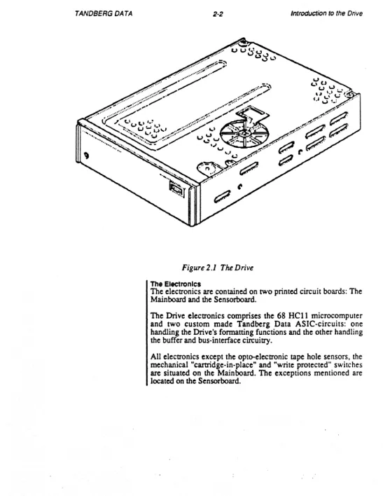
The Drive mechanism is built inside a rigid casting. The mechanism includes a direct-drive capstan motor. a door-locking and ejection system and a head-moving ("worm-wheel/gear") system. Figure 2.1 illustrates the Drive's mechanical outline.
TANDBERG DATA 2-2
Figure
2.1The Drive
The ElectronIcs
Introduction to the Drive
The electronics are contained on two printed circuit boards: The Mainboard and the Sensorboard.
The Drive electronics comprises the 68 HCll microcomputer and two custom made Tandberg Data ASIC-circuits: one handling the Drive's fonnatting functions and the other handling the buffer and bus-interface circuitry.
TANDBERG DATA
Data Block
n~
.
Preamble
2·3 Introduction to the Drive
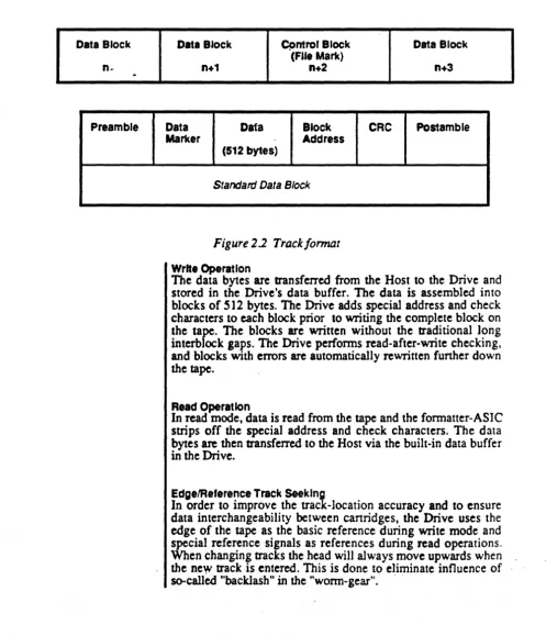
2.3. Tape Format and Drive Operation
Data is formatted into small blocks, each block containing 512 bytes of data. Special address and checking bytes are added to each block. The basic layout is shown in Figure
2.2. The
overheadper
block is very small, nominally 19.5 bytes.Data Block Cpntrol Block Data Block
(File Mark)
n+1 n+2 n+3
Data Dafa Block
CRe
PostambleMarker Address
(512 bytes)
[image:12.617.54.551.185.764.2]Standard Data Block
Figure
2.2Track/onnat
Write Operation
The data bytes are transferred from the Host to the Drive and stored in the Drive's data buffer. The data is assembled into blocks of 512 bytes. The Drive adds special address and check characters to each block prior to writing the complete block on the
tape.
The blocks are written without the traditional long interblock gaps. The Drive performs read-after-write checking, and blocks with errors are automatically rewritten funher down thetape.
Read Operation
In read mode. data is read from the
tape
and the formatter-ASIC strips off the special address and check characters. The data bytes are then transferred to the Host via the built-in data buffer in the Drive.EdgelReference Track Seeking
TANDBERG DATA 2-4 Introduction to the Drive
Track Seek'ng In Write Mode
When the Drive has received the write command, it steps the head down until the forward (lower) recording channel is right above the lower tape edge. The tape is at BOT. Then the Drive starts moving the tape forward, and at the same time stepping the head downwards very slowly. It also starts writing a fixed high-frequency (preamble) panern.
A special detector circuit monitors the output from the read head. As soon as the read head reaches the lower edge of the tape, the read signal disappears and the edge detector informs the microcomputer that the edge is detected. The head is then stepped 50 steps downwards and then again upwards until the detector circuit once more senses the tape edge. This position is marked as the tape Edge, and the tracks funher written are aligned with reference to this position.
The microprocessor will remember this position as long as the cartridge is insened (and power is on), and it will step the head to the accurate track locations due to the high resolution of the stepping system.
Track Seeking In Read Mode
When reading, the Drive will not look for the edge of the tape. No write operation is allowed in read mode. Instead, the microcomputer will look for the long preamble on the fIrst track, using the same edge detector circuit as in write mode. The Drive will sense the upper and lower edge of the reference track and then the microcomputer will calculate the correct center position of the reference track. In this way it is able to find the actual track locations even if the tracks were not recorded in the correct position.
The edge seeking (or reference signal seeking) is performed only between BOT and LP. Nonnally, the Drive has to move the tape backwards and forwards a few times before the head has moved enough to detect the tape edge (or reference signal).
If a cartridge that has been wrinen in another format than the "native" one is read -like QIC-24 format on a 'IDC 3640 or-6O - the Drive may need several passes to determine the correct starting-point on the tape.
TANDBERG DATA
~
&
2-5 Introduction to the Drive
2.4. Drive Block Diagram with Description
All drive operations are controlled by the 68HCll
microcomputer on the Mainboard.
Thisincludes the stepping
and positioning of the head. the control of the capstan motor
speed, the sensing of the tape holes and the communication with
the Host.
Figure 2.3 below shows a block diagram of the Drive .
Micro Motion ... d Processor System
c.pstan System
Re.d
- QIC-<l2 Protocol CirCUit
I+-Handler
- Dynamic RAM Controller -3-way OMA
Controller
Bus-~
Bus Drivers! Receivers~ 64 KByIe
Buffer
~ ~ Write
~ Circuit
- Tape Formatter - Motor Servo
Control
+i Tape Hole
~ - Sensor System
[image:14.620.45.575.194.766.2]Sensor
Figure 2.3 Block diagram o/the Drive
Cepstan System
WriIe!Read Head
....
The capstan motor is controlled by a software controlled and
monitored servo system. Pulse modulation of the motor current
is used in order
toreduce power dissipation
in
the motor.
Head Motion System
The head is moved up and down with a double-screw
("worm-wheel") system. controlled by a stepper motor. The
computer supplies the pulses to the stepper motor. The
micro-computer is also able to detect either the edge of the tape or the
edge of the reference signals by employing the tape edge sensor
electronics.
'
'The WritelAead Head
The head has two recording channels designed for serpentine
recording. Each channel contains a write and a read section.
When writing. the Drive runs a read-after-write check to verify
the recorded data. The head also has a full-width erase part that
erases
allthe tracks on the tape each time the Drive.starts writing
TANDBERG DATA 2-6 Introduction to the Drive
Tape Hole
Sensors
The EOT (End of Tape), the BOT (Beginning of Tape), the LP
(Load Point) and the EW (Early Waming) holes in the tape are
detected by the Mainboard microprocessor using the Tape Hole
Sensor circuit. The detection system includes a sophisticated,
synchronously clocked hardware system to avoid malfunction
and tape run-out.
The Write Circuit
This circuit performs the actual writing on the tape. Infonnation
about the data to
bewritten is received from the Write
Sequencer. The write circuit adapts itself to the type of tape used
(DC300XL. DC600A or DC600XTD).
For recording, the TDC 3640 should use DC600A or
DC-600XTD tapes and the TDC 3660 should only use the
DC600XID ta or uivalent from other manufacturers.
The Read Circuit
The Read Circuit detects each flux transition from the read head
and convens
itto a digital pulse. The circuit is optimized to read
weak signals. thus improving the total system error rate.
The Read Clock Generator
This circuit generates a clock signal which follows the long tenn
variations in the data signal read back from the tape. A· phase
locked loop.is used to control the generation. The circuit is
optimized for OCR encoded data.
2.5. The Formatter Functions
The Formatter comprises:
- Communication microprocessor (68HCl1)
.. Data buffer
- Control circuits for data conversion
- DMA controller
- Host Interface controller
The Data Buffer is designed for optimal performance in disk
back-up applications. The operation is described in detail in
Section 2.7.
TANDBERG DATA 2·7 IntrodlJction to the Drive
2.6. Interface to Host
The interface to the Host conforms with the SCSI standard, revision 17B. Communication between the Drive and the host system is undertaken via a 9-bit bidirectional bus and nine bidirectional control lines.
The Drive accepts commands from the Host. The Host may read the Drive status by asking for the transfer of special status bytes from the Drive. See Chapter 9 for a complete list of available commands. During read and write operations, the data bytes are transferred via the Host Bus. The transfer of each data byte is supervised by the control lines in a handshake operation to minimize timing burden on the host controller.
TANDBERG DATA 2·8 Introduction to the Drive
TANDBERG DATA 3-1 Product Specifications
3.
Product Specifications
This section contains a comprehensive set of specifications for the Drive.
3.1. Mechanical Dimensions and Weight
Standard drive mounting
Fits in 5 1/4" half-height ("slim-line") enclosure for diskette or disk drive. Standard mounting holes for a half-height drive.
Max. dimensions
Weight
44
x
150x
218 mm (1.7.32"x
5.905"x
8.583")1.1 kg (2.4 lbs)
See Section 4.1 for mounting details and mechanical drawings.
3.2. Power Requirements
Voltage Current
+5V 250mA •
+ 12 V motor not running 100mA
+12 V motor running with tape 1.2A
••
+12 V peak value (start·up) 3.9 A
...
... ExcI. the bus termination resistor network.
... Nominal value. Actual value depends on cartridge friction.
. . . Assuming cartridge meeting 3M"'! spec. for torque and friction
Current (A)
3.7 A
t---.,
Sleep fundion turned off (12 V supplied to analog section)
1.3 A +-""'"'7"'-'---""'f--tfttHtttffitiM~""----1.OSA
0.0
r---1====t---o
Motor start ran:tp • T)'Pical.140 rns
T}pica/ cu"ent curve for
+
12V during motor start-up
(Cartridge: Worst case 3MTM inside spec.)
TANDBERG DATA
Voltage variations
Ripple on +5 V and +12 V
Power dissipation
Operating
Storage
Transport
Mode
Operating •
Storage
Transport
+SV±5% +12V±10%
3-2 Product Specifications
Including ripple
Including ripple (No resaictions on the
tum-on sequence).
Maximum 200 mV Peak-to-Peak.
2.25W
IS.OOW
Motor not running.
Typical. motor running with cartridge
insened.
3.3. Environmental Specifications
The following definitions are used in this section:
The unit is unpacked and power is turned on.
The unit
isunpacked and power is turned off.
The unit is packed in original package as when ready for
shipment from factory.
3.3.1. Temperature and Relative Humidity
Temperature (OC) Rei. humidity (%)
+5 - +40 20 - 80
-30 - +60 10 - 90
-30 - +60 10 - 90
• In operating mode these figures are limited by the media. Due to
additional heating coming from internal friction in the canridge, the
maximum surrounding temperature should not exceed 40°C in order
not to violate the maximum temperature rating for the tape canridges
which is 4SoC. Maximum Wet Bulb temperature is 26°C operating.
(See figure below and IMPORTANT-notice in Chapter O. Preface).
Relative humidity ("!o)
80
20
·s·
30· 40 TemperatureP
C)TANDBERG DATA
Operating
Operating Storage Transport
Test method
Mode
Operating
Storage
Transport
Topple Storage
Shock Transport
Shock Storage
3·3
3.3.2. Temperature Variation
Maximum 6°C per hour, non-condensing
3.3.3. Atmospheric Pressure
Product Specifications
53 - 106 kpa [maximum altitude 4000 m (13000 ft)] 15 - 106 kpa [maximum altitude 13000 m (40000 ft») 15 - 106 kpa [maximum altitude 13 000 m (40000 ft»
3.3.4. Vibration
EC-68-2-6
Frequency Peak Displacement Acceleration
5 60
5 58
5
12
-
60 Hz 0.035 mm ±10 %--
500 Hz-
0.5 G-
58 Hz 0.150mm±10%--
500 Hz-
2.0G-
12 Hz 3.5 mm±10%--
500Hz-
2.0G3.3.5. Impact and Shock
Lifted 50 mm and allowed to fall on to each of the four bottom edges and corners. (Horizontal position see section 4.1). (lEC-68-2-31).
Lifted 1.0 m and allowed to fal1 freely on to a hard, rigid surf"lce. Fall sequence includes al1 6 sides and the most critical edge and corner. (IEC-68-2-32).
TANDBERG DATA 3·4 Product Specifications
3.4. Product Performance Specifications
3.4.1. Audible Noise
55 dB (A). Integrated over 60 seconds. Measured at a distance of
1 m in all axes. The Drive free standing.
Worst-case cartridges may increase this figure.
3.4.2. Radiated Electromagnetic Interference
The Drive complies with FCC Rules Pan 15 Subpart J Class B
and VDE 0871 Class B.
3.4.3. Susceptibility to Electromagnetic Interference
An electromagnetic. field of 6 V
1m
will not cause any functional
disturbance. (MIL-SID 462, method RS03, 14 kHz - 1 GHz).
3.4.4. Static Discharge
The Static Discharge is referred to the front door and other pans
of the Drive that are accessible from the front when the Drive is
mounted in a cabinet. The Drive will withstand a discharge of 15
kV from a capacitor of 150 pF via a 150
n
resistor without
malfunction or loss of data. Normal retries are allowed.
3.4.5. Safety Standard
The Drive complies with IEC 380, VDE 0805, UL 478 and
CSA C22.2 - 220m 1986.
3.4.6. Mean Time to Repair
TANDBERG DATA
Predicted ·'mature" MTBF
Head Wear
Motor
Door open/close
Useful LHeCycie
3·5 Product Specifications
3.5. Product Reliability
The predicted reliability of the Drive must
beexpressed in two
pans that will cover the expected random Mean Time Between
Failures (MTBF) for the Drive electronics based on the Power
On
Hours (POH) and the Mean Time to Failure
(MTfF)for the
mechanical pans based on the POH
andthe Duty Cycle.
3.5.1. Electronics MTBF
The predicted MTBF has been calculated using a conservative
Pans Count Model based on data from MIL-STO-217E. This
gives a value for the "mature" MTBF for POH
>1.000 hours.
The expected Early Life Failures can
beestimated by reducing
the MTBF by a factor of 3 (three) for 0 - 500 POH and by 2
(two) for 500 - 1.000 POH.
The predicted "mature" MTBF for the electronics pan of the
TOe
3600Series Drives is:
>
20.000 POH
3.5.2. Mechanics MTTF
The failure rate for these pans is related to how often the Drive
is actually used. In the case of the most critical components
which are the head and the capstan motor, the reliability is
specified as the Mean Time to Failure (MITF) based on the
POH and the Duty Cycle. The MTTR-values are not
accumulative as the wear takes place in paralleL
> 2.000 POH all00
%Duty Cycle (see NOTE
1)> 20.000 POH at 10
%Duty Cycle (see NOTE
1)> 2.000 POH al100
%Duty Cycle (see NOTE 2)
>
20.000 POH at
10 %Duty Cycle (see NOTE 2)
>
15.000 open/close cycles
1:
This figure is based on using DC300XL tapes.
NOTE 2:
Streamin
0eration, NOT extensive stan/sto
0erations.
3.5.3. Useful Life Cycle
This is the period during which the Drive is serviceable either by
adjustment or replacement of defective pans.
.
TANDBERG DATA
Suggested type of media
Number of recorded tracks
Track
width
3-6 Product Specifications
3.6. Functional Specifications
3.6.1. Media
3M DC300Xl 3M DC300XlP 3M DC600A 3M DC600XTO DEI
DEI DEI Ser.1I Gold Plus
137 m (450-foot), cen. for min. 6400 frpi·
137 m (450-foot), cen. for 10000 frpi
183 m (600-foot), cen. for 12500 frpi
183 m (600-foot), cen. for 12 500 frpi
*.
137 m (450-foot), cen. for 10000 frpi
169 m (555-foot), cen. for 10000 frpi
169 m (600-foot), cen. for 12 500 frpi
Or
equivalent tapes from other manufacturers.
*
We strongly recommend using tapes certified for 10 000 frpi
or better for QIC-24 recordings. Only tapes cenified for
12500 frpi should
beused for QIC-120/150 recordings.
•• When you are recording, use DC600A or DC600XTD tapes
- or similar makes with equal mechanical tolerances - for the
TOC 3640 IS-track QIC·I20 version. For the TOC 3660
18-track QIC-I50 version; use DC600Xm tape only! See also
IMPORTANT-notice in Chapter O. about
tape/environmen-taltemperature and humidity restrictions.
3.6.2. Track Width and Location
TOC 3620:
Nine tracks
TOC 3640:
Fifteen tracks
TOC 3660:
Eighteen tracks
TOC3620:
TOC3640:
TOC366O:
0.343 mm ±O.013 mm (0.0135" ±O.OOO5")
0.165 mm ±O.013 mm (0.0065" ±O.OOOS")
0.165 mm ±D.013 nun (0.0065" ±O.OOOS")
TANDBERG DATA
3·7
Product Specifications...
,..".I
Dimcnsian values are
listedon
thefollowinl pale.
Track 5 Trac* , Trac* 7 Track
a
Track 4Track 0
Track'
Track 2 Track.
TrtlCk Locations lor
theTDC 36201QIC·24 9-track Drive
Traclcl.octltiDnslor 1M TDC 3640IQIC-120 IS-track Drive
TID 13
T"'5 TID'
TID 1
TID'
T..:k "
"*"
TID • 7TID 17
""'1
=\
. " . '0TID •
=:
T . . ,. TID "TrtlCkLocOlions/or 1M TDC
.366oIQic~IS018-track Drive
L3 L13
L'. L13
TANDBERG DATA 3·8 Product Specifications
I
The dimensions are as follows:
I
I
TOe 3620/OICo24 TDe 3640/QlCo120I
TDC 36IOIQlCo150LE
1.mmm LE 1.778 nvn LE 1.778 mm(0.070") (0.070" ) (0.070· )
LO 2.59 mm to.107 nwn LO 1.092 mm %0.076 mm LO 1.255 mmtO.076 mm (0.102· to.0042") (0.043- %0.002·) (0.0494" %0.003·)
L1 5.03 mm to.1 07 rrvn L1 2.845 mm %0.051 mm L1 3.740 mm %0.051 rnm (0.19S" :to.0042") (0.112" %0:002") (0.1472" %0.002") L2 1.37 mmtO.107 mm L2 1.626 nvn%O.OS1 mm L2 1.360 mm%O.051 mm
(0.054" ~0.0042") (0.064" %0.002") (0.0535" %0.002") L3 3.81 mm±0.107 rnm L3 4.470 rrvn to.051 mm L3 3.400 mm ±0.OS1 mm
(0.150" ±0.0042") (0.176" to.002·) (0.1339" to.002") L4 3.20 mm±0.107 rnm L4 0.406 nvn %0.051 mm L4 0.340 mm to.OS1 mm
(0.126" :to.0042") (0.016" :to.002") (0.0134" :to.002")
L5 5.64 mmtO.107 mm L5 2.438 mm to.OS1 mm L5 4.080 mm:tO.OS1 mm
(0.222" to.0042") (0.096" to.002") (0.1606" to.002")
L6 1.98 mm to.107 nvn L6 1.219 rrvn to.OS1 mm L6 1.020 mmtO.OS1 mm (0.078" to.0042") (0.048" to.OO2") (0.0402" %0.002")
L7 4.42 mmtO.107 mm L7 4.064 rrvn to.051 mm L7 2.720mmtO.OS1 mm (0.174" :to.0042") (0.160" to.002") (0.1071" :to.002")
L8 0.76 mmtO.107mm) L8 0.406 mm to.OS1 mm L8 0.340 mm to.OS1 mm
(0.030" to.0042") (0.016" to.002") (0.0134" %0.002")
L9 L9 3.251 rrvn to.OS1 mm L9 2.380 mm to.OS1 mm (0 .12S" to. 002·) (0.0937" to.002") L10 L10 0.813 mm to.OS1 mm L10 0.680 mm to.051 mm
(0.032" :to.002") (0.0268" %0.002")
L11 L11 3.658 rrvn to.OS1 mm L11 3.060 mm to.051 mm
(0.144" to.002") (0.1205" to.002")
L12 L12 2.032 mmtO.OS1 mm L12 1.700 mm±0.OS1 rrvn
(0.080" to.002") (0.0669" to.002")
L13 L13 4.877 mm to.051 mm L13 4.760 mm to.OS1 rnm
(0.192" to.002") (0.1874" to.002")
L14 L14 0.813 rrvn to.051 mm L14 0.680 mm ±0.OS1 mm (0.032" %0.002") (0.0268" to.002")
L1S L15 L15 4.420 mmtO.051 rrm
(0.1740" to.002·)
l16 L16 L16 1.020 mmtO.OS1 mm
L17 L17 L17
TANDBERG DATA
Head type
Write channel width
Read channel width
Erase head·
3-9 Product Specifications
3.6.3. Head Specifications
2-channel read-after-write for serpentine recording. Separately mounted erase bar.
TDC 3610: TDC 3630: TDC 3650: TDC3620: TDC3540: TDC3660:
0.343 mm ±G.0l3 mm (0.0135" ±O.OOO5"). 0.165 mm ±G.0l3 mm (0.0065" ±O.OOO5"). 0.165 mm ±O.0l3 mm (0.0065" ±O.OOO5").
0.423 mm ±O.013 mm (0.0167" ±O.OOO5"). 0.267 mm ±O.0l3 mm (0.0105" ±O.OOO5"). 0.267 mm ±O.013 mm (0.0105" ±O.OOO5").
Full rape width erase bar. All tracks
are
erased when writing from BOT on TrackO.
Alignment between TDC 3620: Maximum 0.025 mm (0.01 "). Maximum 0.015 mm (0.006"). read and write TDC 3660:
sections Erase frequency Azimuth ZenIth Type of operation Tape speed standard Tape speed variation Start/stop time Start/stop distance
3.6
MHz
TDC3620: TDC3540: TDC3660:
<
7 minutes-of-arc. (According to ECMA/ANSJ).<
7 minutes-of-arc. (According to ECMA/ANSJ).<
7 minutes-of-arc. (According to ECMAIANSJ). < 15 minutes-of-arc3.6.4. Tape Movement
Streaming
TDC3620: TDC3540: TDC3660:
2.29 m/s (90 ips) 1.83 m/s (72 ips) 1.83 m/s (72 ips)
Shon term (1 Byte): ±6 % with cartridge insened. Long term (512 Bytes): ±2 % with cartridge insened.
[@ 2.29 m/s (90 ips)]: Start time typical: 200ms Stop time typical: 450ms
[@ 1.83 m/s (72 ips)]: Stan time typical: 250ms (See figure) Stop time typical: 400ms
[@ 2.29 m/s (90 ips)]: Stan distance typical: Stop distance typical:
250 nun (9.S") 250 min (9 .. S")
TANDBERG DATA 3-10 Product Specifications
Tape
speed
n~s~---~---~'
o~~~~==~---
Start time
ypical 250 ms
Time (ms)
Typical curve/or tape speed during srarr/srop operations
Recording method
Recording density
Maximum flux density
Block size
Nominal overhead
Write procedure
Read procedure
Recoverable soft error rate
Non-recoverable hard error rate
3.6.5.
Recor~lngSpecifications
NRZI (NON-RETURN to ZERO, change on Or .. rEs) with data encoded according to the 0,2 GCR rules.
IDC 3620: Maximum 315 data bits per mm (8 000 data
IDC 3640/60:
IDC3620: IDC 3640/60:
bits per inch).
Maximum 394 data bits per mOl (10000 data bits per inch).
Maximum 394 ftpmm (10 000 ftpi). Maximum 492 ftpmm (12 500 ftpi).
IDC 3620/40/60: 512 data bytes.
TDC 3620: 19.5 Bytes (Preamble 12, Byte Marker 1, Block Addr. 4, CRC 2 and Postamble 0.5). IDC 3640/60: 23.5 Bytes (Preamble 16, Byte Marker I,
Block Addr. 4, CRC 2 and Postamble 0.5).
Writing always starts from the beginning of Track 0, except when the Host tells the Drive to start writing from the last block recorded.
All tracks are erased when writing from BOT on Track
O.
Tracks are written in an evenly rising order, i.e. 0, I, 2 etc.Reading always starts from the beginning of Track 0 and is perfonned in an evenly rising order, i.e. 0, I, 2, etc.
Media dependent, typically> 108 data bits per error.
> 1011 data bits per error when using DC600XTD or equivaJent media cenified for 12 500 frpi and tested under nominal con-ditions (50 % reI. hum.,
+2SYC,
continuous streaming).I
NOTE:TANDBERG DATA 3·11 Product SpecificatIons
3.6.6. Storage Capacity
TDC3620:
TDC3640:
TDC3660:
137 m (450-foot) tape: 45 MBytes ..
169 m (555-foot) tape: 55 MBytes ..
183 m (600-foot) tape: 60 MBytes ..
183 m (600-foot) tape: 125 MBytes ..
183 m (600-foot) tape: 155 MBytes •
.. Assuming typical tape-error perfonnance.
3.6.7. Head Moving Mechanism
Type of mechanism
Double-screw ("wonn-wheel") mechanism controlled by a
stepper motor.
Head movement
0.005 mm (0.0002") per step, non-accumulating.
per step
Number of steps between adjacent tracks
Type of capstan motor
Servo system
capstan tachometer
BOTIEOT sensor
cartridge sensor
Write protect . . n$Or
Tolerance on maximum operating head travel:
0.03 mm (0.0012") maximum.
TDC3620:
TDC3640:
TDC3660:
Norrrinally 122 steps.
Norrrinally 81 steps.
Norrrinally 68 steps.
3.6.8. Capstan System
High-inenia coreless DC motor.
Dual feedback system using an optical tachometer. Speed
vari-ations are continually controlled by a digital servo system.
Optical with 64 pulses per revolution.
3.6.9. Tape Sensor System
Solid state infrared transmitter and receivers. Synchronous
transmitter/receiver system and digital filtering in drive
micro-processor firmware for noise suppression.
Mechanical
TANDBERG DATA
Basic design
Read clock
ReadlWrlte buffer capacity
3·12 Product Specifications
3.6.10. Electronics
One microcomputer (68HCll) for drive- and fonnatting control, one circuit for buffer- and bus-control and one ASIC-circuit for formatter- and drive-functions. Tape-speed and all write data timing are referred to crystal controlled clocks.
TOC 3620/40/60: Phase-Locked loop, nominally 900 KHz, designed to operate with the GCR-code.
TANDBERG DATA
Mounting positions
Mechanical dimensions
4-1 Mounting Specifications
4.
Mounting Specifications
4.1. General Mounting Information
Recommended mounting position is either horizontal with the indicator to the left, or vertical with the indicator down. The Drive must not be mounted in such a way that the canridge is operated upside down.
1 A .
It
is of the utmost importance to observe that the
aluminum chassis
isnot bent or twisted in any way when
tightening the mounting screws! Note that mounting the
drive top-nush against a nat surface may obstruct the
rubber im eller·fan mounted on the
c:a
stan-motor axle.
The Drive occupies a half-size (or "slim-line")
S
1/4" slot with two standard holes for'3 mm mounting screws on both sides of the Drive chassis.In addition, four 3 mm standard mounting holes are located at the bottom of the Drive (drive mounted horizontally).
See Figure 4.1 for the mechanical dimensions of the Drive. Make sure to leave sufficient external free space to obtain easy open/close operation of the front door when mounting the Drive.
Dimensions in mm. (Dimensions inside brackets in inches).
1
,
General tolerances: +/-0.5 mm (+/0.02-)
•
~
S
!!!. !!!. ~
~~
__
~~~~=*~i
__
~~!
f t
f
[image:30.621.42.537.67.724.2]48.LU __
~l.~-==--=::!=::t:-..J
4Ut
83)TANDBERG DATA 4·2 Mounting Specifications
cable lengths
The maximum cable length from the Drive to the host-interface
is 3 meters (10 feet). However, to increase system noise im·
munity, the cables should
bekept as shon as possible.
The power connector is AMP 172296·1 or equivalent. The
mating connector is AMP 1-480424-0 or equivalent.
ChaSsiS grounding
The signal ground is connected
tothe Drive's chassis through a
1
nFcapacitor located on the Mainboard. The Drive chassis may
beconnected to the system chassis through a "fast-on" connector
at the rear of the Drive. This is only necessary
ifthe Drive
chassis is not adequately grounded to the system chassis through
the mounting screws. (See Figure 4.2). Correct grounding of the
chassis is important in order
toreduce radiated electromagnetic
interference.
I"l
The Drive operated as a stand-alone unit complies with FCC
class B for radiated noise. However, incorrect grounding may
violate this at the system level. As a rule of the thumb, the
srstem should have only one common point between chassis and
sIgnal ground.
A •
As system-mounting and grounding are outside our
control, Tandberg Data cannot be held responsible for any
roblems due to s stems not meetin the FCC rules.
\
.Jumper Field!
Ground Connector
[image:31.627.20.544.43.669.2]T.st Connector
Figure
4.2
Rear View of Drive shpwing
theChassis
Ground-and
theJumper Fieldffesl Connectors
,
TANDBERG DATA 4·3 Mounting Specifications
4.2. Strap Setting/Selecting Drive Number
Most of the TOC 3620/40/60 options are controlled by the EEROM and NOT by using the selection straps at the rear of the Drive. These options are described in the Software Interface pan of this manual. (See Chapter 9. Section 9.3.5 Mode Select). Only the functions and options which are unpractical to handle in this way are controlled by strap settings. The "multi-function" jumper field located at the Drive's rear end supports the following functions:• Selection of Drive number
• EnablinglDlsabling of the Parity Check
• Serial communication for adjustments and tests • Test selection
The layout of the jumper/strap connector is shown below:
Parity Enable (If closed): PARI Serial Communication In: IN Serlll Communlcltlon Out: OUT
&p.clal tl.ts are executecllf this
pin II grounded. - - - '
TEST
OPEN OPEN OPEN OPEN OPEN OPEN OPEN OPEN
4.2.1. Selecting Drive Number
The factory default drive number setting is Drive O. If the Drive has to be set up as a different unit number. the str.!ps have to be connected according to the following table (Strap connected =
CLOSED):
SEL2 SEL1 SELO Meaning
OPEN OPEN OPEN Select Drive 0
TANDBFERG DATA 4-4 Mounting Specifications
~:"
-.-.
UNI.
UII...
Drlv.
Int.rface
L.-'\--+~--I---=~...;=-t-Conn.ctor
Jump.r fleldl
[image:33.630.14.544.41.760.2]T.st conn.ctor T.rmlnatlon resistor (Position +5 V left!) networks
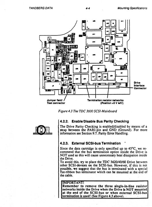
Figure
43The TDC 3600 SCS/-Mainboard
4.2.2. Enable/Disable Bus Parity Checking
The Drive Parity Checking is enabled/disabled
bymeans of a
strap between the PARI-pin and GND (Ground). For more
information
seeSection 9.7. Parity Error Handling.
4.2.3. External SCSI-bus Termination
Since the data cartridge is only specified up to 45°C. we
re-commend that the bus termination option ir:tside the Drive is
NOT used as this will cause unnecessary heat dissipation inside
the Drive.
To avoid this.
tryto place the TOC 3620/40/60 Drive between
other SCSI-devices
onthe SCSI-bus. However.
if (his is not
possibJe.
wesuggest that the bus is terminated with a special
flat-ribbon bus terminator which can
bemounted at the end of
the cable.
TA •
TANDBERG DATA
Ifimm
~
TEST SEL2
CLOSED OPEN
CLOSED OPEN
CLOSED OPEN
CLOSED OPEN
CLOSED CLOSED
CLOSED CLOSED
CLOSED CLOSED
CLOSED CLOSED
4-5 Mounting Specifications
4.2.4. Serialln/Out Communication
The IN and OUT signal pins are used to connect the Drive to cenain test tools. In particular the serial communication is used
for adjusting the Drive with the
TDT 370 BIRD Test System.
4.2.5. Test Functions
The Drive has several test functions that easily can be staned by
setting up a specific code on the select straps (SELO - SEL2), and
by grounding the TEST-pin during drive power-up. The coding
are as follows:
SELl SELO Meaning
OPEN OPEN Drive without Sensor Bd.: Bum-In Test
Complete Drive: Run-In Test
OPEN CLOSED Acceptance Test/SeHtes! 2
CLOSED OPEN Reserved for future use
CLOSED CLOSED Reserved for future use
OPEN OPEN Reserved for future use
OPEN CLOSED Reserved for future use
CLOSED OPEN Production QA Reliability Test
CLOSED CLOSED Prod. QA Head and Motor Wear Test
I
The different tests are described in detail in Chapter 10, SectionTANDBERG DATA
Disk
Floppy Disk
Printer
4-6 Mounting Specifications
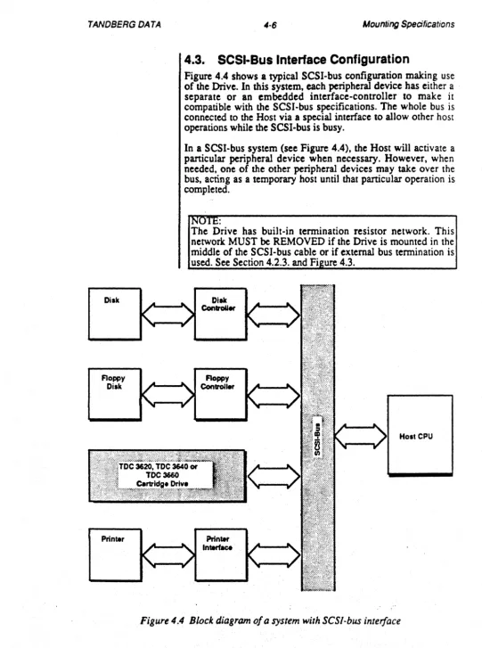
[image:35.629.14.555.41.768.2]4.3. SCSI-Bus Interface Configuration
Figure 4.4 shows a typical SCSI-bus configuration making use of the Drive. In this system. each peripheral device has either a separate or an embedded interface-controller to make it compatible with the SCSI-bus specifications. The whole bus is connected to the Host via a special interface to allow other host operations while the SCSI-bus is busy.
In a SCSI-bus system (see Figure 4.4). the Host will activate a particular peripheral device when necessary. However. when needed, one of the other peripheral devices may take over the bus, acting as a temporary host until that particular operation is completed.
I NOTE:
The Drive has built-in termination resistor network. This network MUST be REMOVED if the Drive is mounted in the middle of the SCSI-bus cable or if external bus termination is used. See Section 4.2.3. and Figure 4.3.
Disk Controller
Host CPU
TANDBERG DATA 4·7 Mounting Specifications
4.4. Heat Dissipation
The Drive dissipates typically 15 W when running. and 2.25 W in stand-by. A pan of this energy is dissipated in the canridge itself while the tape is running. As a rule of the thumb. the base· plate temperature of a typical cartridge will increase about
7°e
during the 10 minutes it takes to read or write a 450 feet tape at 90 ips.NOTE:
To avoid unnecessary temperature build-up when the Drive is in the idle mode. i.e. when the tape is riot running, power to the write- and read-circuitry is turned off.
The maximum allowed internal temperature in the Drive in operating mode is limited by the media. The specifications for the 3M cartridge is 5 - 45°C, humidity at 20 - 80 %. and maximum Wet' Bulb temperature is set to 26°C. (See also Section 3.3.1).
Care should be taken at system level to provide sufficient cooling possibilities to meet the cartridge specifications above. It is of course of imponance not to terminate the SCSI-bus inside the Drive as this will dissipate unwanted heat inside the drive unit. We recommend that the SCSI Drive is located in the middle position of the SCSI-bus; in which case NO Drive termination circuitry is required. See Section 4.2.3.
It is also possible to use specially designed bus-terminators on the cable itself.
'A
.
Do NOT cover the ventilation holes in the chassis whcll mounting the Drive! Note that mounting the drive top-nush a ainst a nat surface will im de air now!
It should be noted that in some applications it may be necessary to provide forced ventilation.
It is imponant that the canridge operating specifications are not violated. Thus, when testing at system level the two following control points are recommended for temperature measurements:
1. The air surrounding the head. (Close to the point where
the tape touches the head-surface).
TANDBERG DATA 4-8 Mounting Specifications
TANDBERG DATA
Data reliability
Features given special attention
5-1
5.
Data Reliability
5.1. Summary
Data Reliability
This chapter deals with data reliability. It stans with a general introduction including imponant points for the system designer, and then goes on to describe the algorithm employed during write- and read- operations when errors occur. The important message is that ERRORS WILL OCCUR, even in the best designed system, and the Drive is designed to deal with these errors in a very efficient way.
5.2. Generallntroduction
Data reliability is a function of many variables such as:
Tape and canrldge quality Head quality
The design of the read- and wrlte-electronlcs, Including read clock circuit
Capstan quality
Capstan motor and servo system
Quality of the mechanical locking system, the canrtdge-guides and the head positioning system
Quality of tape handling
Drtve mounting In the host chassis Cleaning and maintenance
Cleanness of the air surrounding the Drive and tape Quality of the power·supply connected to the Drive Quality of the way clata-errors are treated by the formatter Operating and storage environments
The Drive is designed and constructed for optimal quality to ensure a low error rate. Here are some of the features that have been given special attention:
The Drtve mechanism Is mounted on a rtgld casting The locking mechanism ensures that the canrldge always
locks In the same position
The head screw (''Worm·wheet") system Is able to position the head within very narrow tolerances
The write and the read channels Incorporate many new features which Improve the recording and reading on marginal tapes
A very sophisticated and Intelligent retry .. lgorlthm that Includes off·track alignment for reading marginal data blocks
TANDBERG DATA 5·2 Data Reliability
Reduce the However, it is very imponant that the system in which the Drive possibility of errors is to be mounted also is designed to reduce the possibility of
errors:
Checking list
Reliable mounting (no vibration)
Good shielding and grounding to reduce Influence from external electromagnetic fields
Adequate ventilation
Easy access to the head for cleaning purposes (preferably using the Tandberg Data TOC Cleaning canrJdge Kit)
It is also very important that only high quality tapes are used. When they are not used, the tape cartridges should be stored in a place where temperature and humidity are within specifications. A void direct sunlight. A new tape or a tape that has been stored for a long time should always be run to EW and rewound to Load Point before the fIrst write operation takes place. For best results. it is recommended that a wind/rewind operation is performed on all cartridges immediately after insenion. The Drive can be programmed to do this automatically. Prior to use, a cartridge should be kept for at least 24 hours in climatic conditions similar to those in which the Drive operates. (See also Section 5.5, Cartridge Conditioning and IMPORTANT-notice in Chapter 0).
With all these points in mind, it is imponant to remember that errors still occur, even on cenified tape. The Drive is designed to handle these errors in the way described in the following paragraphs:
5.3. Write Mode
Data is immediately verifIed by a read-after-write check. The read channel has higher acceptance levels during this operation to detect marginal recordings. The Drive will verify that each block has got the correct Block Address, Block Marker and CRe character. The complete block is checked by using the CRC generator.
The complete list of data checking is:
•
A CRe check Is perfonned on each data block. The CRe polynomlnal has the following fonn:G(x)
=
x16 +x12 + x5 + 1Any single error burst of 16 bits length or less is detected by this code. 99.997 % of bursts of 17 bits length and 99.9985 % of bursts longer than 17 bits are also detected.
•
•
A minimum distance of 0.5 bit cells Is required between adjacent flux transitions.
TANDBERG DATA
Retry procedure
5·3 Data Reliability
• All re.d data II checked .aalnst the COdlna table for GCR encodlna. Any devl.tlon from thll t.ble II m.rked .s an enor.
•
For every block the Drive verifies (by .... dlna) that the Block Marker .nd the Block Address II correctly recorded.If blocks with errors are detected, the Drive tries to rewrite the bad blocks, up to 16 times if necessary, to eliminate the error. The bad blocks are not marked in any way, and may be detected as good blocks when read later. This procedure is described in detail in Section 6.8.
5.4. Read Mode
H a bad block is detected during read mode, the Drive fll'st reads the two good blocks that follow to see if the fll'st block has been rewritten. If it has, the bad block is just skipped.
If a bad block is detected and the two good blocks that follow have higher block numbers, the retry procedure is employed:
• The Drive t ... to .... d the bad block another two times.
•
•
•
If atlll unable to rud the bad block, It tries to .... d the bad block .nother two times, this time with the he.d movad a
1/4 track·wldth off center.
If atlll unable to .... d the bad block. It tries to .... d the bad block .nother two times, this time with the head moved a 114 track·wldth off center In the opposite direction.
If atlll unable to ... ad the bad block, this whole procedure II repeated four times. I ••• the total number of Read Retries II 24 times, 8 tim .. In center track pOSition, 8 th .. In • 1/4 traCk-width off center position upwards and 8 tim .. In a 1/4 track·wldth off center downwards.
• Aft.r 24 Read Retries without luccess, the Drive stops ... dlna.nd reportl a "Hard eno"'. (Unrecoverable data).
TANDBERG DATA 5-4 Data Reliability
Only blocks which cannot be read after this procedure (24
retries)
are
marked
as
badblocks.
NOTE:
By defmition, a "Hard Read Enor" occurs only when
a
block
cannot
be lead aflCrIhe following sequence of operation:
• 24rereads
• Head cleaning with the TDC Cleaning Cartridge Kit
(orsimilar cleaning equipment)
• Complete retensioning of the tape
• Another 24 rereads
If two (or more) good blocks with the same block number are
detected during read-mode (blocks which have been rewritten
during write-mode), the data from the first good block is
transferred to the Host. The contents of the other blocks with the
same block number are just skipped.
5.5. Cartridge Conditioning
Conditioning Nles
The achieveable data reliability is depending on the tape and
cartridge quality. In order to obtain the lowest error rate possible
on a ,iven cartridge, the cartridge should be conditioned
according to the following rules before being used:
•
•
•
lefore use the cartridge shall
becondhloned by exposure
to the actual operating environments for at least
4hours.
(Aefer to Section
3.3.1for the operatlng environment
specifications).
In Write Mode: Each time the cartridge Is Inserted In the
Drive, the tape should
beNn one complete end-to-end
.... (ratenslon), prior to start of the write operatfon.
InAead Mode: If. an "Unrecoverable Aead Error" occurs,
themagnetic head should
becleaned, the tape should
beNn one complete end·to-end pass. and the read operation
started onee more andlaU on the same block before this
error Is classified as permanently unrecoverable.
TANDBERG DATA 6-1 Track. Tape-format and Encoding Specifications
6.
Track, Tape-format and
Encoding Specifications
6.1. Summary
This chapter describes tape format. layout of each track. type of recording, and type of data encoding employed. Information about rewrite operations are included. The tape fonnat conforms with the QIC-24, QIC-120 and QIC-lS0 Standards for data interchange. See The QIC-24 and QIC·02 Standards, Revision D, Pan no. 402732, Pub!. no. 5447, Section 3, The QIC-120 Standard, Revision D.' February 11. 1987 and The QIC-ISO
Standard, Revision J,
May
12. 1987.The different drive versions reads (R) and writes (W) the various ta formats accordin to the followin table:
QIC-11· QIC-24 QIC-120 QIC-150
TOC 3620 R W R W
-
-TOC 3640 R
.
R.
R W-TOC3660 R
-
R-
R W R W• See IMPORTANT-notice below!
In this section the Industrial Standard QIC-24, QIC-120 and QIC-1S0 tape fonnats
are
described. 24. 120 andQIC-ISO are the standard tape fonnats for the
TDC
3620/40/60Drives. Nonnally, the optional QIC-l1 fonnat is used only when it is necessary to read old QIC-ll formatted tapes. The main differences between the 24/120/IS0 and the
QIC-11 format are:
• No ref .... nce trICk II wrttten on Track 0
• Only 1 byte available for block addressing (only 256 different block addresses)
• It II legal to t.rmlnate writing without I ffle mark IS the last block
A •
QIC.ll is NOT an Industry Standard and exists only
in
some • to a certain extent· incompatible versions.
.
Although an (optional) extensive program
isprovided to
allow reading of such
tapes,the lack of standards makes it
impossible for Tandberg Data to give any definite
warran-ties regarding this optional QIC·U read .. compatibility.
~~nding
on the actual.
QIC~l1versionrecorded on the
TANDBERG DATA 6-2
6.2.
Track
Specifications
Track, Tape·format and Encoding Specifications
The tape is recorded serially on nine tracks (TOC
3620/QIC-24)on fifteen tracks (TOC
3640/QIC-120)or on eighteen tracks
(TOe 3660/QIC-150),
one at a time.
Figures 6.1a, 6.1b and 6.1c show the track numbering for
9-,5-and IS-track l'eCOrded tapes respectively.
Figure 6.la Track layout/or the TDC 3620 Drive
DI:
. . . . 1
-...
TANDBERG DATA
P. Prumblll
o • Ca .. Of ConIl'DI 8Ioc:IGI
EW. EaI1y Wamin;
LP. u.s Point
DI_II.loII
01 02 03
D4
05
D6
IIIln"""III (1M"")
0
•
·
,
0.1
·
,.
I
•
o
6·3
U II
•
I•
"
,
•
IIni""'III (Inch.l)
15
4
Ie
2 4
17
Track, Tape-format and Encoding Specifications
01
o.IC",UO"
lOT 10 SIIrI 01 TNIdr. " ' .... nca aullt
u.s Point 10 End 01 TID AtMnca 8ufst .1Id S_" 01 P_bIII 01'1 Ew.I TIDS brly Wltnin; 10 End of De .. 01'1 E_ T _ _ brly WemitlC 10 Sta" 01 "-bill 01'1 OlIo T NIdr.I
End of Ca_ 10 t.c.d Point 01'1 TractIs 3. 5. 1 1 , 13
[image:44.623.59.538.81.701.2]u.s Point 10 EIIII of 01_ 01'1 TIKkI 10 7. '0 15 , 17
Figure 6.1c Track layout/or
theTDC 3660 Drive
Recording is done serially on one track at a time, starting with
Track O. Even numbered tracks (0, 2, etc.) are recorded from
BOT (Beginning Of Tape) towards EOT (End Of Tape), while
odd numbered tracks
(1,3, etc.) are recorded from EOT towards
BOT.
When writing from BOT on Track 0,
alltracks are
simultaneously erased.
TANDBERG DATA 6-4 Track, Tape-format and Encoding Specifications
Data 8 loCk no. 1
Data Block no. 2
6.3. Track Format. QIC-24, QIC-120 and
QIC-150
Each track contains data blocks. control blocks and possibly file mark blocks as shown ·in Figure 6_2. (The QIC-120 Standard does not allow control blocks to
be
written on the tape).Data Data File Data
Block __..__H .. _e __ Block . Mark Block
no. 3 no.n no. n+1 no.n+2
[image:45.629.12.550.46.758.2]Recording direction
•
Figure
6.2TrackformlJts QIC-24, QIC-120 and
QIC-I50
Each data block contains 512 bytes of encoded data. A file mark block contains 512 bytes of a unique data pattern.
The layout of each block is described in Section 6.7.
Data-. control- and filemark blocks
are
recorded without the usual interblock gaps employed in normal block-mode tape recording.6.4. Recording Method
Information is recorded on the tape using the NRZI (NON-RETURN to ZERO. change on ONEs) method where each "}" bit is recorded as a flux reversal. "0" bits give no flux transitions on the tape. but
are
detected by measuring the distance between "}" bits (flux reversals). To avoid long distances on the tape without any flux changes (strings of "0" bits only), the information to be recorded is encoded according to the 0.2 GCR rules. This ensures that the maximum distance between two flux reversals isthree
bit cells ( .. .1001...).6.5. Data Encoding; 0,2 GCR Rules
PriOT
to the recording. the information tobe
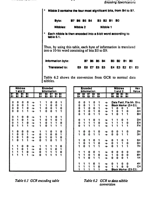
recorded is encoded according to the 0,2 OCR (Group Coded Recording) rules. The operation is as follows:• A byte Is defined as eight bits, numbered from 80 to 87. 8711 the most significant bit.
• Each byte
'1
.eparated Into two nibbles, each nibble contaln-. Ingcontaln-.four bitscontaln-.TANDBERG DATA
Nibble. 11nd 2
I:~
:; :; :
0 0 0 0 ->
0 0 0 1 ->
0 0 1 0 ->
0 0 1 1 ->
0 1 0 0 ->
0 1 0
,
->0 1 1 0 ->
0 1 1 1 ->
1 0 0 0 ->
1 0 0 1 ->
1 0 1 0 ->
1 0 1 1 ->
1 1 0 0 ->
1 1 0 1 ->
,
1 1 0 ->1 1 1 1 ->
6-5 Track, Tape-format and EncodinQ Specifications
• Nibble 2 contains the tour most algnlflcant bits, frOm 84 to B7.
8yte: 87 86 85 84 83 82 81 80
Nibbles: Nibble 2 Nibble 1
• Each nibble II then encoded Into I 5-blt word according to
table 6.1.
Thus, by using this table, each byte of information is translated into a 10-bit word consisting of bits EO to E9.
information byte: 87 86
as
84 B3 B2 81 80Translated to: E9 E8 E7 E6 E5 E4 E3 E2 E1 EO
Table 6.2 shows the conversion from OCR to normal data nibbles.
Encoded information
Encoded Nibbles
I
Hex Information 1.nd 2 Value::
:;
:~ :~:
;:;;~:~ro;; ;;
:~ :~,
1 0 0 1 0 0,
0 1 -> Data Field, File Mk. Blks.1 1 0 0 1 0 0 1 1 1 -> Block Marker (E4-EO) 1 0 0
,
0 0 1 0 0 1 -> 1 0 0 1 9H,
0 0 1 1 0 1 0 1 0 -> 1 0 1 0 AH0 1 0 1 1 -> 1 0 1 1 BH
1
,
,
0,
1 0 1 0 1 0 1 1 0 1 -> 1 1 0 1 DH
1 0 1 1 0 0 1 1 1 0 -> 1 1 1 0 EH 1 0 1 1 1 0 1 1 1 1 -> 1 1 1 1 FH 1 1 0 1 0 1 0 0 1 0 -> 0 0 1 0 2H
0 1 0 0 1 1 0 0 1 1 -> 0 0 1 1 3H <