_ _
~
ALTOS
-586/986
1-1 1: INTRODUCTION
1-2 GENERAL INFORMATION
1-3 RECOMMENDED TEST SEQUENCES 1-4 DATA ENTRY CONVENTIONS 1-4 LOADING THE ADX PROGRAMS 1-7 SPECIAL FEATURES
2-1 2: CLOCK VERIFICATION
2-2 GENERAL INFORMATION 2-2 DISPLAY CLOCK
2-2 SETTING THE REAL TIME CLOCK 2-3 TERMINATE TEST
3-1 3: FLOPPY DISKETTE DRIVE
3-2 FLOPPY COpy 3-4 FLOPPY FORMAT
3-5 FLOPPY VERIFICATION
4-1 4: BARD DISK
4-4 FORMAT DISK DRIVE
Contents
4-6 VERIFY ADDRESSES FOR ALL SECTORS ON DISK 4-6 SEEK TEST WITH OPTIONAL VERIFY
4-8 WRITE ENTIRE DISK 4-9 READ ENTIRE DISK
4-10 SET FLAG BYTE FOR A SPECIFIC SECTOR 4-12 HARD DISK WRITE/READ ERROR TEST 4-15 MISCELLANEOUS FUNCTIONS
4-17 DRIVE UNIT RES ELECTION 4-17 TERMINATE TEST SERIES
5-1 5: RANDOM ACCESS MEMORY (RAM) VERIFICATION
5-2 GENERAL INFORMATION
5-3 SELECT MEMORY TO BE TESTED 5-3 RAM TEST MARCH
5-3 RAM REFRESH TEST 5-4 REPEAT MARCH TEST 5-5 REPEAT REFRESH TEST
5-5 REPEAT MARCH TEST AND REFRESH TEST 5-6 TERMINATE TEST
7-1 7: BAG~IC ~APB OBI~ 7-2 WRITE/READ AND VERIFY TEST
7-3 SPACE FORWARD THEN SPACE REVERSE TEST
7-4 REPEAT TESTS A AND B PLUS, FORCE BACKSPACE, CRC, LOSS OF CARRIER ERROR
7-4 RE-TENSION
7-5 TERMINATE TEST
A-I APPBBDIX A: ALms 586 1I0RITOR PROGRAM (Version X.X)
ILLUS'DA~IORS
1-6 Inserting Floppy Diskette A-3 Memory ~ap Altos 586
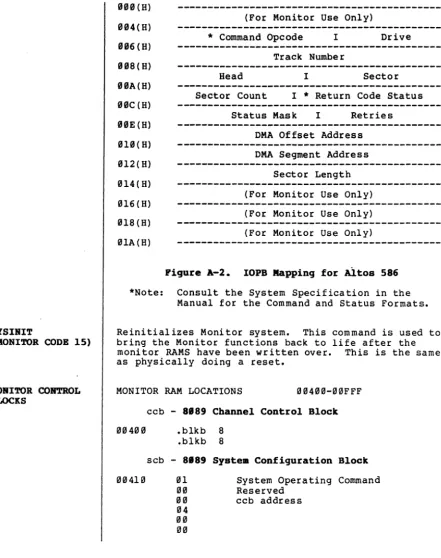
A-IS IOPB Mapping for Altos 586
TABLES
CORTBR'rS 1-2 GENERAL INFORMATION
1-3 RECOMMENDED TEST SEQUENCES 1-4 DATA ENTRY CONVENTIONS 1-4 LOADING THE ADX PROGRAMS 1-7 SPECIAL FEATURES
Introduction
1
1-7 Terminal Disconnect/Reconnect
GBRBBAL
IRPORIIATIOR and understand the Altos 586/986 Computer System Diag-This manual provides information necessary to execute nostic Executive Programs (ADX). The ADX diagnostic packa~e consists of a series of menu-driven utility and veriflcation programs. The verification programs test the:
1. Central processing unit (CPU)
2. Random Access Memory (RAM)
3. Internal communications structure (bus arbitra-tion)
4. Floppy diskette drive 5. Hard disk drive
6. Magnetic tape unit
The ADX programs reside on the 586/986 ADX master diskette that is shipped with each system.
The Altos 586/986 Computer System APX Diagnostic Manual comprises the following seven chapters:
1. Chapter 1, Introduction provides general informa-tion regarding the Altos ADX package and other diagnostic capabilities that accompany the 586 Computing System. This chapter also supplies a
recommended execution sequence for the ADX pro-grams and the initial instructions required to load the ADX programs from the Altos-suppliedADX diskette.
2. Chapter 2, Clock Verification supplies information required to set and verify the system real time clock.
3. Chapter 3, Floppy Diskette Drive gives loading and execution instructions for the copy and format utility programs and the verification program for the floppy diskette drive.
4. Chapter 4, Bard Disk provides the information that is required to load, execute and understand the utility and verification programs associated with the hard disk.
RECOMMENDED
TEST SEQUENCES
6. Chapter 6, Serial Input/Output supplies informa-tion regarding the serial port I/O verificainforma-tion programs.
7. Chapter 7, Magnetic Tape provides the loading and execution instructions for the magnetic tape veri-fication programs.
In addition to the ADX information presented in chap-ters 1 through 7, other diagnostic information is covered in Appendix A. Appendix A deals with the 586/986 Computing System Power-up Diagnostics residing in the 586/986 system monitor program. Although this program is not part of the ADX package, it does provide further diagnostic capabilities.
Review this manual before attempting to load or execute the ADX programs.
Each of the ADX programs may be executed independently as required by the user. However, upon receipt of a new 586 Computer System, there is a recommended test sequence that verifies proper machine operation. This series of tests should be executed prior to any attempt to install an operating system.
The test sequence should proceed as follows:
1. Power-up test executes automatically each time the 586 is powered up. For more information regarding Power-up diagnostics, refer to Appendix A.
2. Load and execute the floppy verification tests as described in Chapter 3. After these tests run successfully, make two backup copies of the ADX diskette. Store the ADX master diskette in a secure location and ~roceed with the rest of these tests with one of the copies.
3. Load and execute the RAM verification test as described in Chapter 5. Two complete passes of the "Repeat March Test and Refresh Test" option should be run.
4. Load and execute the Hard Disk Read/write Error Test option in the Hard Disk Verification program. Instructions for using this program are located in Chapter 4.
DATA BNTRY
CONVBRTIONS
LOADING THB
ADX PROGRAMS
To communicate instructions that enable the reader to load and execute the ADX programs, certain data entry conventions are used throughout this manual. These include:
1. Information that the user is to enter in response to a prompt appears in boldface type: for example, enter Y, or by naming the key to press: Press the Escape key. <CR> indicates that the Return key should be pressed. For example:
Reply Y or N <CR>
2. Alphabetic data may be entered in upper- or lower-case; thus, either C<CR> or c<CR> is acceptable. 3. Pressing the Return key usually enters the data
that has been previously entered. Occasionally, the data is automatically entered when a key is pressed to make a selection from a menu and no <CR> is required. Entering <CR> as a response to a prompt has the effect of entering a iii for a numerical prompt, or No to a Y/N prompt.
4. To erase the last character typed, use Control-H. 5. To erase an entire entry, use the Rubout or Delete
key.
The following information describes the step-by-step procedures required to load the ADX programs into the 586/986 Computing System.
1. Turn the system and terminal power on/off switches to on.
2. Press the Space bar within two seconds after the following message appears on the display screen:
PASSED POWER-UP TEST
ALi'OS COMPU'l'BR SYSTEMS - 586 Monitor Version X.X
Press-any key to interrupt boot
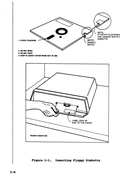
3. When the following prompt appears, insert the floppy diskette into the disk drive (figure 1-1), close the drive door and press the number 2 key.
Bnter [1] to boot froll Bard Disk Enter [2] to boot froll Floppy Disk Bnter [3] to enter Monitor
The ADX program will be read from the diskette and loaded into memory. The Altos Diagnostic Executive master menu will be displayed as follows:
bp586 vz.z
AL'rOS DIAGIIOS'.rIC BXBCU'.rIVB
ACS586/986 - Vz.z
Copyright (cl 1983 Altos Computer Systems
Master (Al (B) (C)
(D)
Diagnostic lIenu Clock Verification Ploppy Copy
(B) (P) (G) (B)
Bard Disk Verification RAIl Verification
Serial Verification '.rape Verification Ploppy Por.'Jlat
Ploppy Verification Enter:
A brief description of the diagnostic programs and utilities follows:
CLOCK
VERIFICATION
FLOPPY COpy
FLOPPY FORMAT
FLOPPY
VERIFICATION
HARD DISK VERIFICATION
RAM
VERIFICATION
Allows real-time clock to be set, then displays data entered. Verifies whether or not clock is functioning.
This utility copies the diskette ver-batim. The program does not verify. This utility formats the diskette in either MP/M, Xenix, or ADX diagnostic format.
Basic test for diskettes and diskette drives. The basic mechanical functions of the drive and its media integrity are tested for validity.
A collection of hard-disk utility and test routines. Utilities include the formatter, a routine to flag bad sec-tors. Diagnostics include quick tests, fault isolation tests, and long exercise routines.
Memory test routine. This program exer-cises the main CPU (8986 central proces-sing unit), tests the refresh circuitry, conducts fault isolation tests, verifies long exercise routines, and parity
1. AVOID TOUCHING
2. DO NOT BEND
3. DO NOT DROP
4. KEEP IN JACKET COVER WHEN NDT IN USE.
PROPER INSERTION
NOTE:
IF NOTCH IS COVERED, YOU CANNOT WRITE ON DISKETTE
[image:11.541.104.498.37.607.2]SPBCIAL FEATURES
Terainal Disconnect/ Reconnect
Test Start/Stop
SERIAL
VERIFICATION
TAPE
VERIFICATION
Serial I/O ports tested and verified. If the console port (1) is bad, other ports cannot be tested.
Verifies that the optional Magnetic Tape Unit (MTU) is properly installed and functioning by exercising the tape drive mechanism and performing write/read functions.
To load and execute any of the programs listed on the Master Diagnostic Menu, refer to the appropriate chap-ter as listed in the table of contents.
Special features have been added to the ADX package. They are designed to give the user greater control and flexibility. These special features include the capa-bility to disconnect the console terminal while execu-ting a test and the ability to stop and restart any given test.
The user has the option of disconnecting the terminal and reconnecting it without disrupting the integrity of the test in progress. This is accomplished by entering control P (Ap), which causes the following display:
[Disconnect]
TO reconnect the terminal to the system, enter a con-trol P (Ap ) and the terminal is reinstated to the
system (see reconnect display below). This action is necessary if there is only one terminal connected to the system at a time. If more than one terminal is on the system, then the terminal connected to the highest numbered port (or the first terminal connected to the system) is designated as the 'master terminal'. It receives all test data during ADX operation. If the master terminal is removed, the terminal connected to the lowest port number becomes the master terminal and receives all pertinent data from the test.
[ Reconnect]
The user may stop and restart any of the tests. The user simply enters a control-S (AS) and the test stops (this is visually apparent on the screen/printer). To restart the test, enter a control Q (AQ) and the test starts. This routine does not harm the integrity of
..
CON'rBlllTS 2-2 GENERAL INFORMATION 2-2 DISPLAY CLOCK
Clock Verification
2
GBIIBRAL
IRPOlUIA'rIOR
DISPLAY CLOCl(
SBftIRG 'rilE REAL 'rIIIB CIDCK
This routine verifies whether or not the system real-time clock is functioning and allows it to be set. The system realtime clock reflects the year/month/date, hour/minute/second, and day of the week. After the clock is set, the clock data is displayed on the screen. Re-enter the clock data if an illegal entry message appears or if the clock is not advancing one second at a time.
A backup ba ttery prov ides the power to run the clock during a power outage or when the system is turned off. The clock must be reset during the following instances:
(1) leap year - will not automatically. display 29 days in the month of February, (2) year end - will not
automatically advance from December 31, 1983 to January 1, 1984.
To use the Clock Verification programs lQad the ADX diskette as described in Chapter 1. When the Master Diagnostic Menu is displayed on the terminal screen, select option A. The following display appears:
ACS586 Real 'rime Clock Verification
vx.x
Real 'riae Clock Main lIenu
(A) Display Clock (B) 'rerainate this 'rest (B) Set Clock
Enter:
Entering option A on the Real-Time Clock Verification menu displays the. system Real-Time Clock in the follow-ing format:
'riae -Tae Tiae -Tae 'riae
-9 jan 1-983 9 jan 1983 9 jan 1983 9 jan 1983 9 jan 1983
thr thr thr thr thr 15:7:58 15:7:58 15:7:59 15:7:59 15:8:1
This display continues to update every half second. Press the ESCAPE key to return the program to the Clock Verification Menu.
To set the clock, enter option B from the menu. The prompts require the year/month/date, hour/second/min-ute, in two-digit numerical entries. The day of the month is entered as a digit 1 through 7, for example:
~IRA'.rE '.rES'!'
6
=
Saturday 7 '" Sundayany other
=
illegal entryAfter making the proper entries, the program displays the clock as it was set. If an error was made, select B to reset the c19Ck correctly.
Selecting option C, Terminate this test, causes the following prompt to be displayed:
Insert ADZ Diskette and hit (CR> to return to Main Kenu
CON'l'ERTS 3-2 FLOPPY COpy
3-4 FLOPPY FORMAT
Floppy Diskette Drive
3
FLOPPY COPY
The ADX programs for the floppy diskette drive include utility programs and one diagnostic program. These programs are as follows:
1. Floppy copy (utility) 2. Floppy format (utility)
3. Floppy verification (diagnostic)
To use the floppy ADX programs load the ADX diskette as described in Chapter 1. When the Master Diagnostic Menu is displayed on the terminal screen, proceed to the appropriate section in this chapter and follow the instructions.
To proceed with the floppy copy utility program as described below, it is assumed that the ADX diskette has already been loaded as described in Chapter 1.· If this is not the case, do so before continuing with this section.
To use the floppy copy utility program, perform the following steps:
1. Enter B at the Master Diagnostic Menu Prompt. The following display appears on the screen:
AL'l'OS COMPUTER SYSTEMS
(A) DISKETTE Copy routines (B) Terminate this test Enter:
2. Enter option A at the prompt. The following dis-play appears on the screen:
*.*
ACS586 DISKBTTE COPY ROO'rIRBS VERSIOR VX.X***
Bit ESCAPB key to terminate this test This routine is done in two parts.
Insert the diskette to be copied from Press any key when ready
3. Insert the diskette to be copied from into the disk drive. Press the Space Bar to start the copy process. The display shows that the utility is copying (reading into memory) the diskette from track 0(H) to 27(H), the first portion to be copied. Once this is complete, the following dis-play appears on the screen:
4. Insert a formatted diskette (which will be copied onto) in the disk drive. Press the Space Bar. The utility now transfers (writes from memory) the data onto the diskette, again showing the track position from ~(H) to 27(H). Once this is com-plete, the following display appears on the screen:
Insert the diskette to be copied from Press any key when ready
5. Re-insert the original diskette (which contains the information to be transferred) into the disk drive. Press the Space Bar. The utility now reads the second half of the diskette, showing position from 28(H) to 4F(H). Once this is com-plete, the following display appears on the screen:
Insert the diskette to be copied to Press any key when ready
6. Re-insert the diskette, that is to receive the information into the diskette drive. Press the Space Bar. The utility is writing the second half of the information to the diskette, showing the position from 28(H) to 4F(H). Once this is com-plete, the following display appears on the screen:
Diskette copy completed
Bit Escape Key to terminate this test. This routine is done in two parts. Insert the diskette to be copied from Press any key when ready
After the copy routine is complete, the program returns to the following menu:
ALTOS COMPUTER SYSTEMS
(A) Diskette Copy routines (B) Terminate this test If additional diskettes need to be copied, option A can be' re-selected.
Selecting option B, Terminate this test, causes the following prompt to be displayed:
PIDPPY POlUlAT
These instructions reboot the system and return the program to the Master Diagnostic Menu.
After creating a copy of a diskette, it is recommended that the Floppy Verification diagnostic be run to check out the new diskette.
This procedure is used to format blank diskettes and must be accomplished prior to performing any Floppy Copy operations.
To proceed with the floppy format utility program as described below, it is assumed that the ADX diskette has already been loaded as described in Chapter 1. If this is not the case, do so before continuing with this section.
To use the floppy format utility program, perform the following steps:
1. Enter C at the Master Diagnostic Menu Prompt. The screen displays the following:
Select
(A) (8)
BDter:
***
ACS586 PIDPPY POlUIAT vx.x***
Pormat IIP/. Systea XBNIX Systea
(C)
(D)
ADX system diskette Terminate Test
2. Enter the appropriate letter for the type of for-mat to be placed on the disk. Note that the Floppy Verification program described in this manual uses the common MP/M format. Select A for MP/M operating systems. Select B for XENIX oper-ating systems. Select C to format a blank disk which will later have the ADX program copied onto it. The following display appears on the screen:
Do you want track verification? [yIn]?
If the response is yes each sector is verified during the format process. The following prompt displays:
Press <ESC> to terminate this routine Insert Diskette to be formatted in Drive I Ready to start? (y or Y for yes)
FLOPPY
VBRIFICATIOB
cylinder
xx
The xx represents the number of the cylinder that is being formatted at any given time.
Upon successful completion of the formatting routine, the display is scrolled up to include the following:
Format Coapleted Select
(A)
(B)
Enter:
Format lIP/II System
XBNIX System (C) (D)
ADX system diskette Terminate Test
The track verification prompt affects the execution time of the formatting routine. With a no response, completion of the routine takes approximately one
minute. A yes response increases the execution time to approximately four minutes.
Each time the format routine is completed, the Select Format menu reappears, allowing the user to format whatever number of floppy disks that may be required. To terminate the format utility, select option D from the menu. The following message is displayed:
Insert ADX diskette and hit <CR> to return to lIain lIenu This action causes the system to reboot and returns the program to the Master Diagnostic Menu.
The Floppy Verification program verifies the floppy disk control circuit on the CPU board, the floppy disk drive, and the media integrity of the diskette under test.
To proceed with the floppy verification program as described below, it is assumed that the ADX diskette has already been loaded as described in Chapter 1. If this is not the case, do so before continuing with this section.
To use the floppy verification program, perform the following steps:
1. Format a blank diskette as described in section 3.2 as a blank diskette is required for this test. 2. Enter D at the Master Diagnostic Menu prompt. The
***
ACS586 Ploppy Disk Verification vx.x***
ALTOS COIIPU'l'BR SYS'rBIIS
(A) Ploppy disk 'rest and Analysis (8) 'rerainate this test Enter:
3. Enter option A. The following is displayed: ***~ Bit ESC to exit this test
****
Do you wish to write on aedia [YiN]?
This question allows selection of a destructive or non-destructive test. An ".- response starts a non-vola-tile read test. The following messages appear:
Load diskette in the drive to be tested Bit any key when ready to start
When any key is pressed, the following message appears just under the "Hit any key ••• " prompt:
Pass - 1 READ PRASB
x
This indicates that the diskette is being read, and it is in the first pass. The x represents the track number being read at any given point during the test. This test continues until the Escape key is pressed. Pressing the escape key terminates the test, displays the test results, and returns the program to the Floppy Disk Verification menu (note the display that follows). Pass
=
2READ PRASB 15
'rotal Passes
=
2****
READ PRASB ERROR CRT=
I WRITB PRASB CRT=
I****
***
ACS586 Ploppy Disk Verification vx.x***
ALms COIlPU'rBR SYS'rBIIS
Ploppy Disk 'rest and Analysis
****
Bit BSC to exit this test****
Do you wish to write on media [yiN]?
Load diskette in the drive to be tested Bit any key when ready to start
CAUTIO.
If a destructive test is chosen (i.e., if Y is entered) the data on the disk being tested is lost.
The following message appears:
Is diskette really scratch [yIN]?
If the. (no) option is selected, the following prompt re-appears:
Load diskette in the drive to be tested Bit any key when ready to start
If Y is selected the following message appears on the screen just under the last message:
Pass-l
WRID PHASE
z
This is the start of the diskette test. First a data pattern is written on all portions of the diskette (the x under the word WRITE represents the track number that is being written to at that moment). Then the entire diskette is read and compared.
During the read phase of the test, the track indicator block shifts down, and the words READ PHASE are dis-played just under WRITE PHASE.
The "WRITE PHASE" and "READ PHASE" messages indicate the start of each portion of the operation. The "WRITE PHASE" is the input of a pattern onto the diskette. The "READ PHASE" is the verification process, which checks if the data was actually input to the diskette surface. The test continues to alternate between these two phases until the Escape key (ESC) is pressed. This action returns the program to the Floppy Verification menu.
A minimum complete test cycle consists of one write phase and one read phase. When the "WRITE PHASE"
If an er ror message is suspected to have been caused by bad media, try another diskette to see whether it is the diskette or the drive. A sample portion of the errors f'Qund in a test is shown below:
Pass - I
n I H PBASB
readVvrite error cylinder-' bead-' sector-I status-" readVvrite error cylinder-' bead-' sector-2 status." readVvrite error cylinder-' bead-' sector-3 status-" readVvrite error cylinder-' bead-' sector-' status-" readVvrite error cylinder-' bead-' sector-S status-', readVvrite error cylinder-' bead-' sector-6 status-" readVvrite error cylinder-' bead-' sector-7 status-" readVvrite error cylinder-' bead-' sector-I status-" readVvrite error cylinder-' bead-' sector-' status-" readVvrite error cylinder-3 bead-' sector-I atatus-" readVvrite error cyU.ader-3 bead-' sector-2 status-" readVvrite error cylinder-3 bead-. sector-3 status-" readVvrite error cylinder-3 bead-' sector-3 status-" readVvrite error cylinder-3 bead-' sector-S status-" readVvrite error cylinder-3 bead-' sector-6 status-" readVvrite error cylinder-3 bead-. sector-7 status-" readVvrite error cylinder-3 bead-. sector-I status-" readVvrite error cylinder-3 bead-' sector-' status·"
~tal Passes - I
****
llBAD PBASB BR1IOIl eft -,
1IRIR PBASB BIlROIl orr - 3P****
To terminate the Floppy Verification test, select op-tion B on the Floppy Disk Verificaop-tion menu. The following menu is displayed:
COR'rBRTS 4-3 4-4
4-6 4-6
4-8 4-9
4-11/1
4-12 4-15 4-17 4-17
Menu Descriptions FORMAT DISK DRIVE
Hard Disk
4
VBRIFY ADDRESSES FOR ALL SECTORS ON DISK SEEK TEST WITH OPTIONAL VERIFY
WRITE ENTIRE DISK READ ENTIRE DISK
SET FLAG BYTE FOR A SPECIFIC SECTOR HARD DISK WRITE/READ ERROR TEST MISCELLANEOUS FUNCTIONS
The Hard Disk Verification routines are a collection of utility and diagnostic programs. To execute Hard Disk Verification, follow the ADX loading procedures de-scribed in Chapter 1. When the Master Diagnostic Menu appears, enter option B. After approximately l~ seconds, the terminal displays the following sign-on message and menu:
*** AeS586 Diak Verification vx.z ***
Specify the BARD DISK to be used
(A) Firat Diak (B) Second Diak
Bater:
To use the hard disk programs, the intelligent I/O controller must be initialized. This task is accom-plished by performing the following steps:
1. Press A to select the internal hard disk'drive. Option B should be selected if a peripheral disk is to be tested. The following menu is displayed on the screen:
Specify the SYSTER MODEL nu.ber
(A) ACS586-1' (4 hd, 3.6 cyl) (e) ACS586-3' (6 hd, 512 cyl)
(B) AeS586-2. (6 hd, 316 cyl) (D) ACS586-U (8 hd, 512 cyl)
2. Select the appropriate model number option for the
586 system being tested. The serial number/iden-tification plate on the bottom of the system pro-vides the model number.
~
586-19
586-2~
586-39 586-49
~able 4-1. Bard Disk Specifications
Storage Number of
Capacity (unformatted) Cylinders
12.76 megabytes 19.14 megabytes 31.99 megabytes
42.66 megabytes
396
3~6
512 512
Number of ~
4
6
6
8
For example, select A to test a 586-19 system drive. 3. When the model number is selected (e.g., select
option A for the 586-1~), the system recalibrates itself according to the information supplied. The terminal displays the following message:
idc loaded
Menu Descriptions
****
Bard Disk Test Facility 1983****
(A) Format Disk Drive(B) Verify Addresses for all Sectors (C) Seek test with optional Verify (D) Write entire Disk
(E) Read entire Disk
(F) Set Flag Byte for a Specific Sector (G) Bard Disk Write/Read Error Test (B) Miscellaneous Functions
(1) Drive unit reselection (J) Terminate this test series Bnter:
The following is a brief description of each menu function. To execute a test refer to the appropriate section in this chapter.
A. For.at Disk Drive. The hard disk is formatted prior to shipment from the factory. Formatting places the cylinder and sector addressing on the disk, and blocks out the data areas that can be written to on the disk. It is usually not necessary to reformat a hard disk in the field. Formatting destroys any prior data
(user files, flagged bad sectors) on the disk. I f it is necessary to reformat the hard disk, the "Flag Bad Sector" program must also be run.
B. Verify Addresses for All Sectors. This reads the addressing information (drive, head, cylinder, sector, buffer, etc.) on the disk to verify its availability and integrity. No data is read or destroyed in this program. This is a good, quick test of format integri-ty.
C. Seek Test with Optional Verify. This test permits specification of two cylinders that the disk controller accesses alternately and continually. The main use of this test is for cylinder address/data fault isolation. It is typically run while using electronic test equip-ment.
D. Write Bntire Disk. This wr ites a user- or factory-specified pattern to all sectors of the disk. This test can be used to erase an entire disk.
B. Read Bntire Disk. This reads data from every sector on the disk, and compares that data to a user-or factuser-ory-specified pattern. It is normally used after the "Write Entire Disk" program to verify suc-cessful data retention.
FORMAT DISK DRrvB
the factory. This feature can be used in the field if a bad spot develops on the disk, or if the disk has been re-formatted.
G. Bard Disk write/Read Test. This test writes a user- or factory-specified pattern over one cylinder, or the entire disk, reads it back, and compares the data for integrity. The test can also be used as an exerciser to work the disk for an extended period of time (i.e., overnight). It reports on the test results at the end of the period and/or at the end of each pass.
B. Riseellaneous Functions. There are two miscel-laneous functions. The first suppresses or enables the display of the disk status error message. This can be disabled while running some repetitive operations for the purpose of checking the drive with electronic test equipment. The second function displays the contents of a selected sector on the screen in hexadecimal and ASCII.
I. Drive Unit Reseleetion. This returns to the recon-figuration options of the test to allow any necessary changes to be made.
J. Terainate this test series. This option reboots the system to exit the Hard Disk Verification test series and returns the program to the Master Diagnostic Menu.
The hard disk is formatted prior to shipment from the factory. Formatting places the cylinder and sector addressing on the disk and blocks out the data areas. This must be done before any data can be written on the disk. It is not usually necessary to run this program in the field. Formatting/reformatting destroys any prior data on the disk.
One of the major repercussions of formatting/reformat-ting is that any flag indicators of known bad sectors are erased. These bad sectors are flagged prior to shipment and are noted on the error map provided with the hard disk. Sectors previously marked as bad are considered valid after formatting. Unless these sectors are re-flagged as bad sectors, data written to them may be lost.
CAUTIOR
This format utility changes data on the bard disk and may cause loss of user data.
1. Select program A, the following display appears:
*** DO ROT ROR THIS TBST WXTHOOT PBRKISSIOR PROB YOUR -LOCAL ALTOS - DEALER ***
Do you want to continue?
The distributor will attempt to determine whether for-matting the hard disk is actually necessary. Call ALTOS customer service only if your distributor sug-gests it.
If not reformatting the disk, enter R or <CR> to return to the Hard Disk Verification Menu.
To reformat the hard disk, follow the instructions provided by your Altos dealer. Performing these in-structions will cause the following prompt to be dis-played at the terminal.
*** THIS TEST WXLL BRASB PILBS OR THB BARD DISK. ***
Do you want to continue? [Y/R]?
To continue, enter Y.
The format process then starts. Each cylinder number is shown on the screen as it is formatted.
When the disk has been formatted, the following message appears on the screen:
entire disk formatted
The program then returns to the Hard Disk Verification menu.
VERIFY ADDRESSES POR ALL SEC'1'ORS ON DISK
SEEK TEST WITH OPTIONAL VERIFY
This test reads the addressing information for every sector of every cylinder on the disk to verify its availability. No data is read; nothing is written or erased.
The identification area of every sector on the hard disk contains addressing information which consists of the head, drive, and sector numbers. This test reads and verifies those numbers. If that information cannot be read, that particular portion of the sector should not be used and should be flagged as bad.
The identification area also contains flag byte infor-mation (where sectors can be flagged as bad), and a Cyclic Redundancy Check (CRC) value. The CRC is a value developed by the circuitry when it writes data on the sector. When data is read from the sector, a CRC value is again generated and compared to the stored value as a check on data integrity.
To execute the address verification program, the Hard Disk Verification option must be loaded as described at the beginning of this chapter. Proceed as follOWS to execute the address verification program:
1. Select program B from the Hard Disk Test Facility menu. The screen displays:
Press any key when ready to start the test.
The verification process then starts. Each cylinder number is shown as it is verified.
When verification is complete, the message sector verification complete
displays on the screen and the program returns to the Hard Disk Verification menu.
NOTE
The "Set Flag Byte" program can be used to flag bad sectors. Sectors listed as "Expected Errors," however, should not be flagged, since they have already been flagged as bad.
Two cylinders are alternately and continually accessed by the disk controller during program execution. The user selects the two cylinders to be accessed. The test verifies the address information (head 0 and sec-tor 0) of each cylinder specified, unless verification is disabled.
To execute the option must be this chapter. test:
seek test, the Hard Disk Verification loaded as described at the beginning of Proceed as follows to execute the seek
1. Select option C, the screen displays:
Press any key when ready to start this test After a key is pressed the program prompts the user to specify two cylinder addresses to set the test bounda-ries.
Enter SBBK first cylinder number:
2. Enter the first cylinder number to be used. For example, for a drive with 306 cylinders enter from 8 to 385, .. then <CR). The next prompt is:
Enter SBEK last cylinder number: 3. Enter the second cylinder, then <CR>.
Proceeding with the example, the maximum seek distance is from 0 to 305. The minimum seek distance can be obtained by specifying the same cylinder. Normally, there is no reason to do this.
The next prompt is:
Do you want test verification of cylinder numbers [yIN]? Normally, yes (Y) is selected. As the program accesses each cylinder, it reads and verifies the sector 0
address information. Disabling the verification, by selecting H, enables the test to run faster. This is done only when using electronic test equipment to check part of the seek process where maximum speed is desi~ed and the verification of address does not matter.
The seek process starts as soon as "y" or nN" is en-tered. The cylinder numbers are alternately displayed (under the message "Hit ESC to end this test") as each seek is performed.
WRI~ ERTIRB DISK This program writes a user or factory specified pattern to all sectors on the disk. The companion program, "Read Entire Disk," verifies the data retention of the disk.
To execute the write Entire Disk program, the Hard Disk Verification option must be loaded as described at the beginning of this chapter. Proceed as follows to exe-cute the write program:
1. Select option D on the Hard Disk Test Facility menu, the screen displays:
***
~IS ~T WILL BRASE PILES OR ~E BARD DISK***
Do yoa want to continae [y/R]?If R is selected, the program returns to the Hard Disk Test.Facility menu. If Y is selected, the screen displays:
Do yoa want to 1I1UTB a specific pattern [y/R]?
If R or <CR) is entered the default pattern (E5E5) is selected.
If Y is selected, the program prompts you to choose a pattern.
Select pattern:
Patterns can be specified by entering:
*1 - for a 256 byte hexadeciaal (II-PP) pattern OR - select a one- or two-byte pattern ~4 chars),
interpreted in hexadecimal
(Press <CR> after entering the pattern.) If a pattern is not acceptable, a message appears on the display. Specifying *1<CB> selects a 256-byte block of all hexa-decimal values from 00-FF as the pattern.
The one- or two-byte patterns can be specified. Enter one to four hexadecimal characters (0 through F), for example, A55A.
The pattern buffer is a four-position right-justified buffer with leading zeros. Therefore, an entry of E5 results in a pattern of 00E5.
READ BlftIRB DISK
disk. Once the entire disk has been written to, the following is displayed on the terminal screen:
Entire disk write completed
This program reads a user or factory specified pattern from all sectors on the disk. This companion program to the Write Entire Disk program can verify the data that was previously written to the disk.
To execute the Read Entire Disk program, the Hard Disk Verification option must be loaded as described at the beginning of this chapter. Proceed as follows to exe-cute the read program:
1. Select option B on the Hard Disk Test Facility Menu, the screen displays:
Bard disk READ display options are: (A) Don't display data if any error. (B) Display only if eRe error.
(e) Display only if COMPARE error. (D) Display if COMPARE or STATUS error. Enter:
Selecting options A or B results in the immediate execution of the Read Entire Disk program. The number of the cylinder being read is displayed below the menu. Selection of options
e
or D displays the following prompt:Specify patterns by entering:
*1 - for a 256 byte bexadeciaal ("-PP) pattern OR - select a one- or two-byte pattern (~4 cbars),
interpreted in bexadeciaal. Select pattern:
Press <CR> after entering pattern. If a pattern is not acceptable, a message is displayed.
Specifying *1 selects a 256-byte block of all hexadeci-mal values from OO-FF as the pattern.
The one or two byte patterns can be specified. the same one to four hexadecimal characters (0 F) that were specified during the Write Entire program. Failure to use the same pattern will
in COMPARE er rors.
Enter through Disk result
Sft PLAG BUB FOR
A SPBCIPIC SBCmR
The program displays each cylinder number as it reads the disk.
If an error occurs the following is displayed on the screen:
**
COIIPARB BBBOR**
diak
1I0
error ca.aand-xx drive-x head-x cylinder-xxx sector-xx status-xxThe display screen then fills with the first half of the data buffer showing the data read from the disk. When the screen is first filled with the first half of the buffer data, it displays:
Bit any key to display the other half
When the screen f ills again wi th the second half of the buffer data, it displays:
Bit any key to continue
Continue the display by pressing any key. To exit, press the ESC key and the program returns to the Hard Disk Verification Menu.
This utility flags a sector as bad, that is, one not to used for storing data. Usually, any bad sectors are flagged before shipment of the system. This utility can be used in the field in case a bad spot develops on the disk, or when the disk has been re-formatted and it is necessary to re-flag known bad sectors. The flag location is in the identification area, which also holds the sector addr.essing and the CRC characters. Sectors to be flagged can be specified in two ways: 1. as shown on the error map provided with your
system - by track, head, byte count, and length in bits
2. by entering a specific cylinder, head, and sector address. (This is the way the program normally displays errors.)
For information on removing the error map from a sys-tem, see the note at the end of this section.
1. Select option P on the Hard Disk Test Facility menu, the screen displays:
***
THIS TEST WILL BRASE PILES ON THE BARD DISK.***
Do you want to continue [yIN]?If N is selected, the program returns to the Hard Disk Test Facility menu. If Y is selected, this prompt is displayed:
Bard Disk PLAG BAD SEC~R options are: (A) Disk Error Rap
Enter:
(B) Cylinder, Bead, Sector
Enter A. or B
For option A, read the information off the disk error map and enter it in the same form. The follow ing prompt appears:
Enter cylinder number: xx <CD> Enter Bead number: x <CD> Enter Byte count: xx <CD> flagging sector x
Bad Sectors have been flagged Then the screen displays:
Bard Disk PLAG BAD S~R options are:
(A) Disk Error Rap (B) Cylinder, Bead, Sector Enter:
For option B, you can enter the information in the form used by error messages given by other Hard Disk Verifi-cation programs. The prompts are as follo~s:
Enter cylinder number: xx <CD> Enter Bead number: x <CD Enter Sector count: xx <CR> flagging sector x
Bad Sectors have been flagged
Bard Disk PLAG BAD SBC~R options are:
(A) Disk Error Map (B) Cylinder, Bead, Sector Enter:
Press ESC to terminate the test.
JIAlU) DISI[ WRI'rB/
RBAD ERROR '.rEST
ROTE
The Hard Disk Error Map is taped to the drive inside the system when it is shipped from the factory. Any bad sectors shown on the map are flagged before shipment of the system. The only time this map would be needed to flag sectors is after reformatting the hard disk or for verification ttat all bad sectors have been flagged. The program flags bad sectors but does not allocate alternate sec-tors to be accessed in their place. This function is handled differently by various operating systems.
This test writes a specified pattern over the entire disk, reads it back, and compares it. The test can be used as an exerciser in order to work the disk for a long time (such as overnight). The results are reported a t the end of the test.
This test has two phases. The first writes and reads a variety of patterns to all sectors of the disk. This phase continues until terminated by simultaneously pressing the Control key and A key (shown in test as CNTL-A). The program then immediately aborts the test and begins the second phase.
In the second phase, the program fills the disk with ESES and automatically flags all nbad sectors. n It displays the final error count.
Baplanation of test result terainology:
Soft Brror. An unsuccessful attempt to read data, shown as a CRe error. The operation is retried. If the operation succeeds on the first or second retry, each prior failure is counted as a nsoft error. n Bard Brror. If the third retry at a read fails, the sector is considered to have a "hard error. n
Bad Sector. A sector that has a hard error is flagged as a nbad sector,n and is not to be used for data storage. This is done in the final phase of the test. When program G is selected, the screen displays:
***
~IS TBST ~LL BRASB FILBS OR TBB JIAlU) DISK***
Do you want to continue [Y/R]?
Press any key to start
When a key is pressed, the following options are shown. Bard disk Reliability error display options:
(A) Display error summary at end of each pass
(B) Display error summary only at the end of the test Enter:
Option A displays the soft and hard error statistics at the end of each pass.
Option B displays the hard and soft error statistics only after the test is terminated using a Control-A. Selection of option B also allows the test to be run without a terminal. The terminal may be disconnected after the test is started by using the procedure de-scribed in Chapter 1 of this manual. In this manner the test may be run for long periods of time without tying up a terminal. To terminate the test, follow the reconnect instructions described in Chapter 1.
Selection of option A results in the following prompt:
Display data if a CRC error [yiN]?
If Y is selected the data buffer is displayed on the screen in the event of a CRC error.
The next prompt (first prompt if option B was selected from the Error Display Options menu) is:
Do you want to test cylinders individually? [yiN]?
If N is se:':'ected, the program uses a pre-defined data pattern (DB6C) that is rotated three times for each pass; i.e., in sequence DB6C, B6CD, 6CDB, and CDB6 are each written to and read from the cylinder(s) being tested.
If Y is selected, the following is displayed on the screen if the entire disk is being tested:
As aany as four (4) patterns may be specified, as follows: Enter one or two byte pattern interpreted in hexadecimal Select Pattern 11:
Select Pattern 12: Select Pattern 13: Select Pattern 14:
If Y is specif ied for the "Do you want to wr i te a specific pattern?" prompt and a single cylinder is being tested the following prompt appears at the termi-nal:
Select Pattern:
A one to four hexadecimal character should be entered and followed by <CR>. The next prompt to appear is:
Enter cylinder to be tested
The program begins to execute after the cylinder number and <CR> are entered.
This program continues writing and reading until stop-ped by pressing the CNTL-A. The test aborts immediate-ly and displays:
Pass count: 1
Soft error statistics: Pattern write fault eRC
D86CB I
86COB I
6COBB I
C086B I
Bard error statistics:
error
I I I I
Pattern write fault eRC error
D86CB I I
86COB I I
6COBB I I
C086B I I
RBF I I I I bad
RlIF bad
I I I I
Bit any key to display more information
sector
"
"
I I sector"
"
"
"
Pressing a key displays the following summary:
cap error
I I I
"
cap error
I
"
"
IBeads - x Cylinders - xxx as specified for this drive 50 soft errors recorded
80 hard errors recorded Bit any key to continue
Pressing a key causes the test to continue. If a specific cylinder is being tested, you are asked "Do you want to test another cylinder? [YiN]? If you select Y, you are requested to:
Enter cylinder to be tested.
IIISCELLARBOOS FUNCTIONS
If errors did occur the program flags as bad any sec-tors that had hard errors or soft errors that occurred more than three times. The following message is dis-played:
••••• Bad sectors have been flagged.
A pause of several minutes occurs while the program writes a pattern of hexadecimal ESES to all sectors. The last message is:
••••• Disk Reliability Test Terminated.
The program then returns to the Hard Disk Verification menu.
This program provides two functions. The first sup-presses or enables the display of the disk status error message for Hard Disk Verification programs. This display is ordinarily enabled, but may be disabled when running some repetitive operation while checking the disk drive with electronic test equipment. The second function displays the contents of a selected sector on the screen in hexadecimal and ASCII.
To execute the Miscellaneous Functions program, the Hard Disk Verification option must be loaded as de-scribed at the beginning of this chapter. Proceed as follows to execute the Miscellaneous Functions program. 1. Select option B on the Hard Disk Test Facility
menu, the screen displays: lIiscellaneous lIenu
(A) (B)
(C)
Enter:
Select Disk Brror STATUS display option Display a Sector
~erainate this test
If A is selected, this prompt shows:
Do you want the Disk Brror STATUS message displayed [yIN)? Reply Y or R to enable or supress display of status
errors for Hard Disk Test Facility programs. The pro-gram then returns to the Miscellaneous menu.
If B, Display a Sector, is selected from the Miscellaneous menu, you are prompted one 1 ine at a time -to enter the cylinder, head, and sec-tor numbers. Press Return after each entry. The menu prompts are as
*
DISPLAY BARD DISK SECTOR*
Enter cylinder number:Enter head nuaber: Enter sector number: where
Cylinder number value ranges from ta-3taS.
Head number value ranges from ta-3 for Ita-megabyte disk drives.
Sector number ranges from ta-lS.
The contents of the sector are then displayed on the screen. They are shown in hexadecimal on the left, ASCII on the right if displayable. Sixteen bytes are shown per line. Hexadecimal numbers on the left aid in locating the exact displacement of any byte in the sector, from ta to talFtaH. (Only the first half of the sector contents are displayed on the screen: press any key to display the second half. The displacement num-bers for the second half are a duplicate of the first half.) A sample is shown below:
BDter cylinder nuaber: 12 BDter head nuaber: 1 BDter sector nllllber: 3
•••••• : 85858585 85858585 85858585 858585BS ••••••••••••••••••
•••• 1.: BS858585 BSBS8585 BSBSBS85 BSBSBSB5 ••••••••••••••••••
•••• 2.: 85B585BS BSBSBS85 85B5BSB5 8585BSB5 ••••••••••••••••••
•••• 3.: 85BSBSBS B585BSB5 BSBSBS85 B5B5BSB5 ••••••••••••••••••
•••• 4.: 85BS85BS BSBS8585 B585B5BS BSBSBSBS ••••••••••••••••••
•••• 5.: BSBSBS85 BSBS8585 BS85BS85 B5BSBSB5 ••••••••••••••••••
•••• ,.: BSBSBSBS BSBSBSBS BS85BS85 B5BSBSB5 ••••••••••••••••••
•••• 7.: BS85BSBS BSB58585 BS85BS85 85BSB5B5 ••••••••••••••••••
•••• 8.: 85BS8585 BS8585BS BSB585BS BS85B5BS ••••••••••••••••••
•••• ,.: BSBSBSBS BSBS85BS BSBSBS85 BSBSBSB5 ••••••••••••••••••
•••• AI: 858585BS BSBSBSBS B5BSBS85 BS85BSBS ••••••••••••••••••
... : BS8585BS BSBS8585 BS8585BS BSB5B585 ••••••••••••••••••
•••• C.: 85BSBSBS BSBSl5BS BS8585BS BSBSBSBS ••••••••••••••••••
•••• D.: 85BSBSBS BSBS85BS BSBSBS85 BSBSB5B5 ••••••••••••••••••
•••• 81: 85BS85B5 BSBS85B5 B5BSBSBS BSBSBSBS ••••••••••••••••••
•••• P.: B5B585BS BSB58585 BSBSB5B5 BSB5B5B5 •••••••••••••••••• Bit any key to display the other half
...
: B5B5B5BS BSB5BS85 BSB5B585 B5BSBSBS * ....••..•..•••••••••• C.: BS8585BS B5BS85BS 85BSB585 B5B5B5B5 - •..•••...•••.••• *
••• ID.: BSB5B5BS B5BSBS85 BSBSBSBS BSB5B5B5 * ....•.•.••...••• *
•••• 81: 85BSB5BS BSBSBS85 B5BSB5BS BSB5BSB5
-
...•
•••• P.: BSBSBSBS B5B5B5B5 BSBSBSBS BSBSB5B5 * ....•... *
DRIVE ORI'I' RBSBLBC'I'IOR
'I'BRIlIRAft
'I'BS'I' SERIBS
This selection returns to the initial prompts of Hard Disk Test Facility menu to allow reselection and defi-ni tion of the dis·k to be tested without rebooting the test. This is typically used when errors were made when the disk was first defined.
To invoke, enter option I on the Hard Disk Test Facili-ty Menu.
Select the appropriate options for your hard disk. Specify the BARD DISK to be used
(A) Pirst Disk Enter:
Specify the SYS'I'BK MODBL nuaber
(B) Second Disk
(A) AeS586-11 (4 hd, 316 cyl) (e) AeS586-31 (6 hd, 512 cy1) (B) AeS586-21 (6 hd, 3.6 cy1) (D) ACS586-41 (8 hd, 512 cy1)
The program returns to the main Hard Disk Test Facility menu.
Selecting option J, Terminate this test, causes the following prompt to be displayed:
Insert ADX Diskette and hit <CR> to return to Main Kenu
CORTBJr.rS
Random Access Memory
5
(RAM) Verification
5-2 GENERAL INFORMATION
5-3 SELECT MEMORY TO BE TESTED 5-3 RAM TEST MARCH
5-3 RAM REFRESH TEST 5-4 REPEAT MARCH TEST 5-5 REPEAT REFRESH TEST
GBBERAL
IRFORIIATIOR RAM ·verification routines are designed and written to test on-board}RAM in the 586/986 system. It is assumed that the person running the routine has a conceptual
knowledge of the computer domain.
RAM Verification executes a variety of dynamic tests to validate the integrity of the 586/986 microprocessor
(Intel 8986) and the on-board dynamic RAM.
RAM verification routines assume that the hardware passed the Power-Up monitor self test. It also assumes that the initial (lower) RAM used for program code and/or data variables is secure and error-free for at least brief periods of time. The loading
Of
RAM586 causes the destruction (write over) of all of the initial proprietary inputs ·(i.e., segment register file, reset bootstrap program 1ump, monitor, user interrupt routines, etc.) that were loaded upon system "boot up· and allows the system and memory to be fully checked out. It creates a modified version of the monitor, allowing all of the normal proprietary oper-ating primitives to be used during normal system and memory testing.. As the user completes the RAM verifi-cation, the system automatically reboots the original proprietary information (the monitor) into the appro-priate memory locations.To execute RAM verification, follow the ADX loading procedures described in Chapter 1. When the Master Diagnostic Menu appears, enter option F. After ap-proximately 19 seconds, the terminal displays the fol-low ing menu:
Kemory (A) (8) (C) (D) (E) (1') (G) Enter:
*** ACS586 RAK Verification Vz.z ***
*** Bit ESC to stop test ***
Test Kenu
Select KellOry to be ~ested (default = lower 1/2 megabyte) RAK Karch Test
RAK Refresh Test Repeat Karch ~est Repeat Refresh Test
Repeat Karch Test and Refresh Test Terminate this test
SELEC'.r MEMORY TO BE '.rES'.rED
RAIl MARCH '.rES'.r
RAIl REPRESH ns'.r
This option allows the user to select upper, lower, or a full megabyte of memory to be tested. To use the Select Memory o~tion, enter A on the Memory Test Menu; The following d1splay appears at the terminal:
Meaory (A) (B) Enter:
Size Menu
Lover 1/2 .egabyte Opper 1/2 .egabyte
(C) Pull 1 .egabyte
When the area of memory to be tested is selected, the program returns to the Memory Test Menu.
This test writes alternate patterns of 9999H (9999) and FFFFH (1111) into the RAM.
To execute the RAM March test, perform the following steps:
1. Select option B on the Memory Test Menu. The test begins immediate execution. The following is displayed at the terminal:
Doing Memory March '.rest Ascending Order
Passed Segment no. 7 Descending Order Passed Segment no. 7 Me.ory March '.rest Passed
The test starts by writing zeros and ones, in ascending order within the RAM, validates them, and displays each 64K segment passed. Then it reverses the process by writing zeros and ones in decending order, further validating the RAM's integrity. Should an error occur, the test displays the error and attempts to complete
the algorithm. .
When the test is complete, the program returns to the Memory Test Menu.
This test verifies that the refresh circuitry is work-ing properly and that data placed into the on-board RAM is retained with integrity.
TO execute the RAM Refresh test, perform the following steps:
RBPBA~ IlARCB DS'!'
DOing Reaory Refresh Test Pattern • 5555
Passed Segment no. 7 Pattern - AAAA
Passed Segaent no. 7
Meaory Refresh '!'est Passed
This test writes a hex pattern (5555) into RAM, waits 10 seconds and verifies the pattern. The second pass writes the compliment (AAAA) hex pattern into the RAM, waits 10 seconds and verifies the results. This test also reports any errors found during the test. After the test is complete, the program returns to the Memory Test Menu. The RAM Refresh test can be interrupted and cancelled by pressing the Escape key.
This test is the same as the RAM March test except tha t it executes continuously until terminated by pressing the Escape key. By running this test for an extended period of time, suspected intermittent memory failures may be isolated. To load and execute the Repeat March test, select option D from the Memory Test Menu. Test execution begins immediately and the following is dis-played on the terminal screen:
***
Pass I***
Doing Meaory Karch '!'est Ascending Order
Paaaed Segment no. 7 Deacending Order Paased Segaent no. 7 Doing Meaory Karch Teat Ascending Order
Paaaed Segaent no. 7 Descending Order Paaaed Segaent no 7 Memory Karch ~eat Passed '!'otal Paaaea - I
Total no. of Karch Brrors - I ~tal no. of Refreah Brrora • I
REPEAT REFRESH TEST
REPEAT MARCH TEST AND REPRESH TEST
This test is the same as the RAM Refresh test except that it executes continuously until terminated by pres-sing the Escape key. By running this test for an extended period .of time, suspectd intermittent memory failures may be isolated. To load and execute the Repeat Refresh test, select option E from the Memory Test Menu. Test execution begins immediately and the following is displayed on the terminal screen:
*** Pass 1 ***
Doing Memory Refresh Test Pattern - 5555
Passed Segment no. 7 Pattern
=
AAAAPassed Segment no. 7
Memory Refresh Test Passed
*** Pass 2 ***
Doing Memory Refresh Test Pattern
=
5555Total Passes - 2
Total no. of March Errors
= •
Total no. of Refresh Errors
= •
By pressing the Escape key the Repeat Refresh test is terminated and a test summary is displayed. The pro-gram then returns to the Memory Test Menu.
This test continuously executes both the RAM March and Refresh tests described earlier in this chapter. The test can be terminated by pressing the Escape key. By running this test for an extended period of time,
suspected intermittent memory failures may be isolated. To load and execute the test, select option F from the Memory Test Menu. Test execution begins immediately and the following is displayed on the terminal screen:
*** Pass 1 ***
Doing Memory March Test Ascending Order
TBRIlIBATE '.rES"l'
DOing Reaory Refresh Test Pattern
=
5555Passed Segment no. 7 Pattern • AAAA
Passed Segment no. 7
***
Pass 2***
Total Passes a 1Total no. of Karch Errors - • Total no. of Refresh Errors - •
By pressing the Escape key the test is terminated and a test summary is displayed. The program then returns to the Memory Test Menu.
Selecting option G, Terminate this test, causes the following prompt to be displayed:
Serial Verification
6
The Serial Verification program has two tests which verify that serial I/O communication is functioning. This is vital because most communication with the sys-tem is via serial channels (i.e., terminal, printer, etc.) •
The serial verification routine is initiated in the following manner:
1. Load the ADX diskette as described in Chapter 1. 2. -Select the serial verification program option from
the Master Diagnostic Menu. When the program is loaded, the screen scrolls up and the serial veri-fication menu appears as illustrated below.
***
ACS 586 Intelligent Serial Channel Verification VX.X***
'rest Ilena(A) Select Terainal Port (B) Bcho Test
Enter:
(C) Barber Pole Test (D) Terainate this Test
Choose option A to select the port that is to be test-ed. The following options will be displayed on the screen:
'feraiDal Port Selection lIenu
(A) Port 1 (P) Port 6
(B) Port 2 (G) Port 7
(C) Port 3 (8) Port 8
(D) Port 4 (I) Port 9 (B) Port 5 (J) Port I I
Select A to test Port 1 first. If the console port (port 1) does not check out, none of the other ports can be verified. The following displays:
Connect a Display to Port 1
Test will continue on Port 1
Test lIenu
(A) Select Terainal Port
(B) Echo Test Enter:
(C) Barber Pole Test (D) Terminate this Test
Press the ESC KEY to terminate the test.
When ESC is pressed, the Test Menu appears again. If C is selected from the Test Menu, all keyboard characters are displayed in a continuous diagonal pat-tern (i.e., barber pole). To terminate this test press ESC. The Test Menu will appear again.
Each port can be tested in the same manner as Port 1. If only one terminal is available the test sequence is as follows:
1. Select the port to be tested from the Terminal Port Selection Menu (this example is for Port 2 so option B is chosen). The following display ap-pears at the terminal:
Connect.a Display to Port 2 Test will continue on Port 2
2. Disconnect the terminal signal cable from the Port 1 jack to the Port 2 jack on the system back
panel. When the cable is connected the test menu will appear as illustrated below.
Test Menu
CA) Select Terminal Port (B) Echo Test
Enter:
CC) Barber Pole Test CD) Terminate tbis Test
3. Select the desired test from the Test Menu. 4. To terminate a test, press the Escape key. The
test is terminated and the program returns to the Test Menu.
To exit the Serial Verification program and return to the Master Diagnostic Menu, select option 0, Terminate this test, on the Test Menu. The folowing prompt appears on the display:
Insert ADX Diskette and bit <CR> to return to Main Menu Following these instructions reboots the system and