Indirect Predictive Control Techniques for a Matrix
Converter Operating at Fixed Switching Frequency
M. Rivera, S. Toledo Faculty of Engineering Universidad de Talca, Curic´o, Chile
L. Tarisciotti, P. Wheeler
Dep. of Electrical and Electronic Engineering University of Nottingham, Nottingham, UK
S. Verne
Dep. of Electrical Engineering
Universidad Nacional de La Plata, La Plata, Argentina [email protected]
Abstract—The direct matrix converter (DMC) has a large
number of available switching states, wherewith, the implementa-tion of predictive control techniques requires high computaimplementa-tional resources. In addition, the simultaneous selection of weighting factors for the control of input and output variables of the converter complicates the system tuning. In this paper, two indirect model predictive control strategies are proposed in order to reduce the computational cost and also to avoid the use of weighting factors. The proposal is enhanced with a fixed switching frequency strategy in order to improve the performance of the full system. Results confirm the feasibility of the proposal by demonstrating that it is an alternative to classical predictive control strategies for the direct matrix converter
Index Terms—current control, matrix converters, predictive
control, finite control set model predictive control, fictitious dc-link.
NOMENCLATURE
is Source current [isAisB isC]T
vs Source voltage [vsAvsB vsC]T
ii Input current [iA iB iC]T
vi Input voltage [vA vB vC]T
idc Fictitiousdc-link current
vdc Fictitiousdc-link voltage
io Load current [ia ib ic]T
vo Load voltage [va vb vc]T
i∗ Load current reference [i∗ a i∗b i∗c]T
Cf Input filter capacitor
Lf Input filter inductor
Rf Input filter resistor
R Load resistance L Load inductance
I. INTRODUCTION
The direct matrix converter (DMC) presents bidirectional power flow and adjustable input displacement power factor with sinusoidal input and output [1], [2]. Several control techniques have been applied to the DMC as Venturini, Pulse Width Modulation (PWM), Space Vector Modulation (SVM) as well as Model Predictive Control (MPC) and Direct Torque Control (DTC) [2]. Among the before mentioned techniques, MPC has emerged as a real alternative for the control of power converters [3]. This control technique predicts the future behavior of the system for each valid state of the converter based on the mathematical model at every sampling time. These predictions are compared with a reference by using a predefined cost function and then, the switching state that
generates the minimal error between the prediction and the reference, is selected to be applied in the next sampling instant. Despite the several progress of MPC for power converters, there are still some issues that are considered as an open research topic. One of them is the variable switching frequency inherent to the classical MPC technique. Both the variable switching frequency operation and the application of a single vector during the sampling period lead to high ripples in controlled variables which affects system performance. Mod-ulated MPC (M2PC) has become one of the most popular techniques which emulates SVM by using MPC [4], [5]. This aproach keeps the advantages of traditional MPC techniques such as fast dynamic response, multi objective control and easy inclusion of nonlinearities and constraints. In addition, it ensures fixed switching frequency and ripple reduction on the output variables, which improves system performance. The proposal consists in the emulation of the DMC as a compose of two converters linked by a fictitious dc-link. This DC decoupling allows a separated and parallel control of both input and output stages, avoiding the use of weighting factors. Also, optimal vectors and their respective duty cycles can be determinded and applied to each power stage by using a predefined switching pattern.
II. MATHEMATICALMODEL OF THEDMC
Figure 1 depicts the topology of the DMC which consists of bidirectional switches connecting the input side with the load side without DC storage device. An LC input filter is con-nected between the supply and the DMC for current smoothing and voltage spike supression. This converter has switching constraints that are derived from electrical considerations. On one hand, the current cannot be interrupted abruptly due to the inductive nature of the load and, also, the input capacitors do not allow short circuiting two input lines. These restrictions can be expressed by:
SAy + SBy + SCy = 1, ∀y=a, b, c (1)
The mathematical model of the DMC is defined by:
vo =T vi (2)
whereTis the instantaneous transfer matrix defined as:
T=
SAa SBa SCa
SAb SBb SCb
SAc SBc SCc
(4)
The concept of fictitious dc-link was proposed by Ro-driguez in the 80’s to modulate the DMC in a simple way and it has been used to simplify also the control of this power converter [6], [7]. The method consists on splitting the converter in an equivalent current source rectifier and a voltage source inverter linked by a fictitious dc-link such as represented in Fig. 2. The rectifier have associated six active current space vectors which are shown in Fig. 3(a) and Table I. The inverter have associated eight voltage space vectors which are represented in Fig. 3(b) and Table II.
iA
iB
iC
ia ib ic
SAa SAb SAc
SBa SBb SBc
[image:2.612.52.281.435.493.2]SCa SCb SCc
Fig. 1. Power circuit of the direct matrix converter.
[image:2.612.41.291.536.673.2]DMC Fictitious Converter
Fig. 2. Representation of the fictitiousdc-link concept for the DMC.
α α
β
i1 (AC)
i2 (BC)
i3 (BA)
i4 (CA)
i5 (CB)
i6 (AB)
v1 (100)
v2 (110)
v3 (010)
v4 (011)
v5 (001)
v6 (101)
v7 (111)
v8 (000)
[image:2.612.328.555.562.628.2]a) b)
Fig. 3. Current and voltage space vectors of the fictitious converter. a) Current space vectors for the fictitious rectifier. b) Voltage space vectors for the fictitious inverter.
TABLE I
VALID SWITCHING STATE ON THE FICTITIOUS RECTIFIER
# Sr1Sr2Sr3Sr4Sr5Sr6 iA iB iC vdc
1 1 1 0 0 0 0 idc 0 -idc vAC
2 0 1 1 0 0 0 0 idc -idc vBC
3 0 0 1 1 0 0 -idc idc 0 -vAB
4 0 0 0 1 1 0 -idc 0 idc -vAC
5 0 0 0 0 1 1 0 -idc idc -vBC
6 1 0 0 0 0 1 idc -idc 0 vAB
TABLE II
VALID SWITCHING STATE ON THE FICTITIOUS INVERTER
# Si1Si2Si3Si4Si5Si6 vab vbc vca idc
1 1 1 0 0 0 1 vdc 0 -vdc ia
2 1 1 1 0 0 0 0 vdc -vdc ia+ib
3 0 1 1 1 0 0 -vdc vdc 0 ib
4 0 0 1 1 1 0 -vdc 0 vdc ib+ic
5 0 0 0 1 1 1 0 -vdc vdc ic
6 1 0 0 0 1 1 vdc -vdc 0 ia+ic
7 1 0 1 0 1 0 0 0 0 0
8 0 1 0 1 0 1 0 0 0 0
III. INDIRECTMODELPREDICTIVECONTROLMETHODS
FOR THEDMCWITHFIXEDSWITCHINGFREQUENCY
An interesting M2PC technique for a DMC feeding an induction machine is presented in [8], [9]. Here, the input and output stages are controlled together by considering predictive models of the input reactive power and the load currents, respectively. These predictions are compared with their re-spective references in a single cost function (so it is necessary also to consider a weighting factor in order to provide more priority to one of the controlled variables). At every sampling instant three active and three zero optimal vectors are chosen and applied to the converter. In this method two main issues are observed: first, the cumbersome task of selecting a set of weighting factors to properly tune the controller and also the management of a large number of available switching states of the DMC. In this paper the concept of fictitiousdc-link is used to solve these issues, proposing an indirect model predictive control for the DMC operated at fixed switching frequency. Two strategies are presented for the rectifier side. The first considers a cost function that minimizes the instantaneous reactive power and the second imposes sinusoidal supply currents. The mathematical model of the rectifier stage is:
vdc= Sr1−Sr4 Sr3−Sr6 Sr5−Sr2 vi (5)
ii=
Sr1−Sr4 Sr3−Sr6 Sr5−Sr2
idc (6)
A diagram of the proposed technique is detailed in Fig. 4. The control of the input side of the converter considers the available switching states and also the corresponding electrical model. As the classical predictive strategy, a prediction model of the source current is necessary for the input side control which is derived from:
dis dt =
1 Lf
(vs−vi)−Rf
Lf
Predictive Model
Cost Function Minimization
Filter 3φAC
Source
io(k)
Sr1(k)
.. .
Sr6(k)
is(k)
is(k)
vs(k)
vi(k)
vi(k)
Q∗(k)
or
i∗s(k)
Qp(k+ 1)
or
isp(k+ 1)
3φ
vdc
Rectifier Switching
Sequence
vropt
[image:3.612.41.291.67.228.2]dropt
Fig. 4. Indirect predictive control strategy for the fictitious rectifier.
dvi dt =
1 Cf
(is−ii) (8)
Because of the predictive controller is formulated in dis-crete time, it is necessary to obtain a discretized model for the source-converter system. By considering the guidelines presented in [10] for the current and voltage predictions, it is possible to define the cost function gr associated to the
minimization of the instantaneous reactive input power:
gr = (vsα(k+ 1)isβ(k+ 1)−vsβ(k+ 1)isα(k+ 1))2
(9) For the second strategy, the cost functiongr is associated
to the input control in theα-β plane which is defined as:
gr = (i∗sα−isα(k+ 1))2+ (i∗sβ−isβ(k+ 1))2 (10)
To define the source current reference of the DMC, please refer to [11]. As shown in Fig. 3(a), there are six sectors which are given by two active current vectors each one ii (as an illustration, the vectors i1 and i2 define the Sector I, Sector II is given by i2 and i3, and so on). Each pair of current
vectors are evaluated for cost function gr at every sampling
timeTs, which means that for each sector two cost functions
are calculated, the first associated to one current vectorgr1and another related to the adjacent current vectorgr2. Next, these cost functions are used to compute the duty cycles which are calculated assuming that they are proportional to the inverse of the corresponding cost function value, whereKris a constant
to be determined:
dr1 = Kr/gr1 dr2 = Kr/gr2 dr1+dr2 = 1
(11)
A new cost function is defined based on the previous duty cycles and cost functions which is given by
grec = dr1gr1+dr2gr2 (12)
This is done, at every sampling time, for each of the six sectors. Finally, the pair of vectors that minimizes the cost
function grec are selected as the optimalvropt to be applied
in the next period. The time that each vector is applied is:
tr1 = dr1Ts
tr2 = dr2Ts
(13)
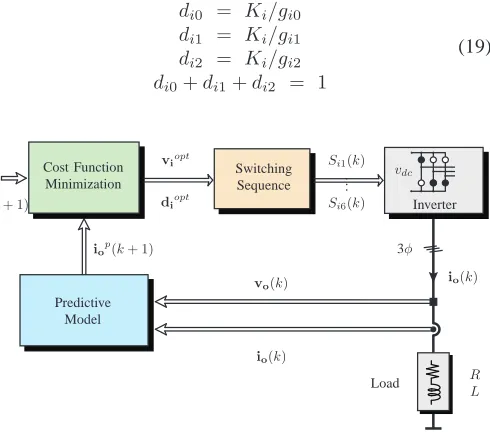
Regarding the inverter side, the control diagram is repre-sented in Fig. 5. In this case the mathematical model is:
idc= Si1 Si3 Si5 io (14)
vo=
Si1−Si4 Si3−Si6 Si5−Si2
vdc (15)
The mathematical model of the load is:
vo=Ldio
dt +Rii (16)
Using these definitions, it is possible to define the prediction model of the output side given by:
io(k+ 1) =c1vo(k) +c2io(k) (17)
where, c1 = Ts/L and c2 = 1− RTs/L, are constants
dependent on load parameters and the sampling time Ts. The
associated cost functiongi for the output stage is:
gi = (i∗α−iα(k+ 1))2+ (i∗β−iβ(k+ 1))2 (18)
Similarly, for the inverter is possible to identify six sectors which are given by two active voltage vectors, as is shown in Fig. 3(b). At each sampling instant Ts, each pair of voltage
vectors and one zero vector are evaluated for cost function gi which means that for each sector three cost functions are
givengi0 ,gi1andgi2. Later, these cost functions are used to compute the duty cycles which are calculated assuming that they are proportional to the inverse of the corresponding cost function, whereKi is a constant to be determined:
di0 = Ki/gi0 di1 = Ki/gi1 di2 = Ki/gi2 di0+di1+di2 = 1
(19)
Predictive Model Cost Function Minimization
io(k)
io(k)
iop(k+ 1)
i∗o(k+ 1)
Si1(k)
.. .
Si6(k)
vo(k)
R L
Load 3φ vdc
Inverter Switching
Sequence
viopt
diopt
[image:3.612.309.554.497.716.2]ti0
4 ti1
2 ti2
2 ti0
2 ti2
2 ti1
2 ti0
4 ts
tr1
2 tr1
2 tr2
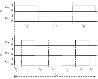
[image:4.612.81.252.64.203.2]b) a) 1 1 1 1 1 0 0 0 0 0 vr1 vr2 vi1 vi2 vi0
Fig. 6. Switching pattern: a) for the fictitious rectifier side; b) for the fictitious inverter side.
With these duty cycles and cost function values, a new cost function is defined:
ginv = di1gi1+di2gi2 (20)
This is done, at every sampling time, for each of the six sectors. Finally, the pair of vectors that minimizes the cost functionginv are selected as the optimalviopt to be applied
in the next period. The time that each vector is applied is:
ti0 = di0Ts
ti1 = di1Ts
ti2 = di2Ts
(21)
After obtaining the duty cycles and selecting the optimal vectors to be applied in both the rectifier and inverter, a switching pattern procedure is adopted (Fig. 6), which applies the optimal vectors with symmetric switching pattern distribu-tion [12].
In the last stage of the algorithm the switching states of the fictitious converter are mapped to the real DMC in order generate proper driving signals. As indicated in (2), the relationship between the input voltagevi and load voltagevo
depends on the state of the switching matrixT. Based on the fictitious definition, the load voltagevo is given as indicated
in (15). At the same time, the fictitiousdc-link voltagevdcis
given by (5). In summary,
vo=
Si1−Si4
Si3−Si6
Si5−Si2
Sr1−Sr4 Sr3−Sr6 Sr5−Sr2 vi
(22) and thus the relationship between the switches of the DMC and fictitious converter is given as:
SAa SBa SCa SAb SBb SCb SAc SBc SCc =
(Si1−Si4)(Sr1−Sr4)
(Si1−Si4)(Sr3−Sr6)
(Si1−Si4)(Sr5−Sr2)
(Si3−Si6)(Sr1−Sr4)
(Si3−Si6)(Sr3−Sr6)
(Si3−Si6)(Sr5−Sr2)
(Si5−Si2)(Sr1−Sr4)
(Si5−Si2)(Sr3−Sr6)
(Si5−Si2)(Sr5−Sr2)
(23) IV. RESULTS
Simulation results in Matlab-Simulink were carried out for the proposals in both steady and transient states. Both proposals are evaluated under the same parameters which are Cf=21 [µF], Lf=400 [µH], Rf=0.5 [Ω], R=10 [Ω],
L=10 [µH],Ts=50 [µs] and a simulation step of 1 [µs].
[image:4.612.84.248.623.733.2]A. Results in Steady State
Figure 7 and 8 results of steady state of the converter operating with unity power factor. Figure 7(a) shows a source currentisA which is in phase with its corresponding voltage
vsAwith also has a THD of 12.65%. In this case, the current
is affected by the resonance of the input filter. The effect and performance of the input filter is also reflected in this figure where high order harmonics present in Fig. 7(b) are eliminated as expected.
In Fig. 7(b) it can be observed the commutated input current iA, which is given as function of the DMC switches and the
load currents io. Fig. 7(b) also shows the effect of the input filter resonance in the capacitor voltage vA. A very good
tracking of the load currents io to its respective references
i∗
o is observed in Fig. 8(a) with a sinusoidal waveform and
a THD of 1.18%. In this case the reference is established as I∗
o=12.5 [A]. Figure 8(b) shows the voltage waveform at the
load side, where the commutated waveform has an envelope ripple also due the input filter resonance.
Figure 9 and 10 also show waveforms in steady state conditions for the indirect predictive controller with imposed sinusoidal source currents. In this case, it is possible to observe a better performance of the system because the effect of the input filter resonance is mitigated in both currents and voltages. Figure 9(a) is observed a source currentisA which
tracks very well its respective reference i∗
sA with a THD of
4.09%, being also in phase to its respective voltagevsA. Again,
the effect and performance of the input filter is also reflected in this figure where high order harmonics present in Fig. 9(b) are eliminated as expected. A very good tracking of the load currentsio to its respective references i∗o is observed in
Fig. 10(a) with a sinusoidal waveform and a THD of 0.96%.
B. Results in Transient State
A frequency change from I∗
o=10 [A]@20Hz to
I∗
o=12.5[A]@100Hz in the load current is applied to
the converter in order to evaluate the performance of the proposed strategies in terms of dynamic response.
Figures 11 and 12 result from the application of the in-stantaneous reactive power minimization strategy. Figure 11(a) shows the voltage and current at both sides of the filter when a current step is applied to the load. In Fig. 12(a) is observed a good dynamic response of the load currentioto its respective reference i∗
o with a very fast dynamic response and a very
(a)
(b)
Time [s]
0.075 0.08 0.085 0.09 0.095 0.1 0.105 0.11 0.075 0.08 0.085 0.09 0.095 0.1 0.105 0.11
-30 -20 -10 0 10 20 30 -15 -10 -5 0 5 10 15
Fig. 7. Simulation results of the proposed method with instantaneous reactive power minimization in steady state: (a) source voltagevsA[V/25] and source
currentisA[A]; (b) capacitor voltagevA [V/10] and input currentiA[A].
(a)
(b)
Time [s]
0.075 0.08 0.085 0.09 0.095 0.1 0.105 0.11 0.075 0.08 0.085 0.09 0.095 0.1 0.105 0.11
[image:5.612.338.523.66.213.2]-400 -200 0 200 400 -10 0 10
Fig. 8. Simulation results of the proposed method with instantaneous reactive power minimization in steady state: (a) load currentsio[A]; (b) load voltage va[V].
observed in Fig. 11(b) which are produced by the commutation of the switches.
Figures 13 and 14 result from the application of the im-posed sinusoidal source currents strategy. Figure 13 shows the voltage and current at both sides of the filter when a current step is applied to the load. In both cases it is observed a very good tracking of the load current to its respective reference.
V. CONCLUSION
In this paper have been presented an indirect model predic-tive current control strategy with minimization of the instanta-neous reactive input power and other with imposed sinusoidal source current for a direct matrix converter operating at fixed switching frequency. The method uses the idea of fictitiousdc -link in order to separate the control of both input and output stages of the converter. By doing this, it is possible to reduce the complexity of the control, the operation at fixed switching frequency but also avoid the calculation of a suitable weighting factor for the control of both input and load currents variables. By considering the proposed strategy, a new alternative has emerged for the control of a direct matrix converter.
(a)
(b)
Time [s]
0.075 0.08 0.085 0.09 0.095 0.1 0.105 0.11 0.075 0.08 0.085 0.09 0.095 0.1 0.105 0.11
-30 -20 -10 0 10 20 30 -15 -10 -5 0 5 10 15
Fig. 9. Simulation results of the proposed method with imposed sinusoidal source currents in steady state: (a) source voltagevsA[V/25], source current
isA[A] and its respective referencei∗sA[A]; (b) capacitor voltagevA[V/10]
and input currentiA[A].
(a)
(b)
Time [s]
0.075 0.08 0.085 0.09 0.095 0.1 0.105 0.11 0.075 0.08 0.085 0.09 0.095 0.1 0.105 0.11
-400 -200 0 200 400 -10 0 10
Fig. 10. Simulation results of the proposed method with imposed sinusoidal source currents in steady state: (a) load currentsio[A]; (b) load voltageva [V].
ACKNOWLEDGMENTS
The authors would like to thank the financial support of Programa en Energ´ıas CONICYT - Ministerio de Energ´ıa ENER20160014, FONDECYT Regular 1160690 Research Project and 14-INV-097 CONACYT-FIUNA Project.
REFERENCES
[1] L. Empringham, J. Kolar, J. Rodriguez, P. Wheeler, and J. Clare, “Technological issues and industrial application of matrix converters: A review,” Industrial Electronics, IEEE Transactions on, vol. 60, no. 10, pp. 4260–4271, Oct 2013.
[2] J. Rodriguez, M. Rivera, J. Kolar, and P. Wheeler, “A review of control and modulation methods for matrix converters,” Industrial Electronics, IEEE Transactions on, vol. 59, no. 1, pp. 58–70, Jan 2012.
[3] S. Vazquez, J. Rodriguez, M. Rivera, L. G. Franquelo, and M. No-rambuena, “Model predictive control for power converters and drives: Advances and trends,” IEEE Transactions on Industrial Electronics, vol. 64, no. 2, pp. 935–947, Feb 2017.
[image:5.612.74.260.66.215.2](a)
(b)
Time [s]
0.04 0.045 0.05 0.055 0.06 0.065 0.07 0.075 0.08 0.04 0.045 0.05 0.055 0.06 0.065 0.07 0.075 0.08
[image:6.612.337.523.66.214.2]-30 -20 -10 0 10 20 30 -15 -10 -5 0 5 10 15
Fig. 11. Simulation results of the proposed method with instantaneous reactive power minimization in transient state: (a) source voltagevsA[V/25], source
currentisA[A] and its respective reference i∗sA[A]; (b) capacitor voltage
vA[V/10] and input currentiA[A].
(a)
(b)
Time [s]
0.04 0.045 0.05 0.055 0.06 0.065 0.07 0.075 0.08 0.04 0.045 0.05 0.055 0.06 0.065 0.07 0.075 0.08
-400 -200 0 200 400 -10 0 10
Fig. 12. Simulation results of the proposed method with instantaneous reactive power minimization in transient state: a) load currentsio[A]; b) load voltage va[V].
[5] S. A. Odhano, A. Formentini, P. Zanchetta, R. Bojoi, and A. Tenconi, “Finite control set and modulated model predictive flux and current control for induction motor drives,” in IECON 2016 - 42nd Annual Conference of the IEEE Industrial Electronics Society, Oct 2016, pp. 2796–2801.
[6] J. Rodriguez, “A new control technique for ac-ac converters,” IFAC Con-trol in Power Electronics and Electrical Drives, Lausanne Switzerland, pp. 203–208, 1983.
[7] P. Wheeler, J. Rodriguez, J. Clare, L. Empringham, and A. Weinstein, “Matrix converters: a technology review,” Industrial Electronics, IEEE Transactions on, vol. 49, no. 2, pp. 276–288, Apr 2002.
[8] M. Vijayagopal, L. Empringham, L. de Lillo, L. Tarisciotti, P. Zanchetta, and P. Wheeler, “Control of a direct matrix converter induction motor drive with modulated model predictive control,” in 2015 IEEE Energy Conversion Congress and Exposition (ECCE), Sept 2015, pp. 4315– 4321.
[9] ——, “Current control and reactive power minimization of a direct matrix converter induction motor drive with modulated model predictive control,” in 2015 IEEE International Symposium on Predictive Control
(a)
(b)
Time [s]
0.04 0.045 0.05 0.055 0.06 0.065 0.07 0.075 0.08 0.04 0.045 0.05 0.055 0.06 0.065 0.07 0.075 0.08
[image:6.612.75.259.66.215.2]-30 -20 -10 0 10 20 30 -15 -10 -5 0 5 10 15
Fig. 13. Simulation results of the proposed method with imposed sinusoidal source currents in transient state: (a) source voltagevsA[V/25], source current
isA[A] and its respective referencei∗sA[A]; (b) capacitor voltagevA[V/10]
and input currentiA[A].
(a)
(b)
Time [s]
0.04 0.045 0.05 0.055 0.06 0.065 0.07 0.075 0.08 0.04 0.045 0.05 0.055 0.06 0.065 0.07 0.075 0.08
-400 -200 0 200 400 -10 0 10
Fig. 14. Simulation results of the proposed method with imposed sinusoidal source currents in transient state: a) load currentsio[A]; b) load voltageva
[V].
of Electrical Drives and Power Electronics (PRECEDE), Oct 2015, pp. 103–108.
[10] C. F. Garcia, M. E. Rivera, J. R. Rodr´ıguez, P. W. Wheeler, and R. S. Pe˜na, “Predictive current control with instantaneous reactive power minimization for a four-leg indirect matrix converter,” IEEE Transactions on Industrial Electronics, vol. 64, no. 2, pp. 922–929, Feb 2017.
[11] M. Rivera, “Predictive control with imposed sinusoidal source and load currents of an indirect matrix converter operating at fixed switching frequency and without weighting factors,” in 2015 IEEE 5th Interna-tional Conference on Power Engineering, Energy and Electrical Drives (POWERENG), May 2015, pp. 641–647.
[image:6.612.75.259.275.422.2] [image:6.612.338.522.284.431.2]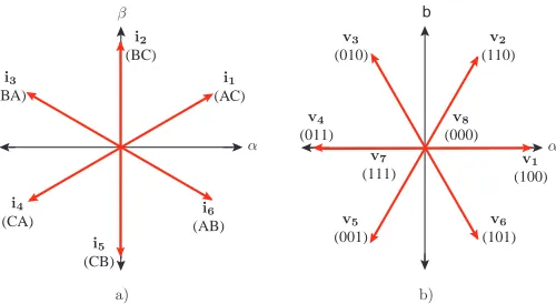
![Fig. 10. Simulation results of the proposed method with imposed sinusoidalsource currents in steady state: (a) load currents io [A]; (b) load voltage v[V].a](https://thumb-us.123doks.com/thumbv2/123dok_us/8583508.370077/5.612.338.523.66.213/simulation-results-proposed-imposed-sinusoidalsource-currents-currents-voltage.webp)
![Fig. 13. Simulation results of the proposed method with imposed sinusoidalsource currents in transient state: (a) source voltageiand input current vsA [V/25], source currentsA [A] and its respective reference isA∗ [A]; (b) capacitor voltage vA [V/10] iA [A].](https://thumb-us.123doks.com/thumbv2/123dok_us/8583508.370077/6.612.75.259.275.422/simulation-sinusoidalsource-transient-voltageiand-currentsa-respective-reference-capacitor.webp)
