Energy storage system for global maximum power
point tracking on central inverter PV plants
Abstract
Central inverters are the most common configuration for large-scale photovoltaic systems. Under partial shading or any non-uniform conditions on the photovoltaic plant, several power maxima may arise. Conventional perturb and observe and other classical maximum power point tracking algorithms are capable of tracking a local maximum, but can not guarantee to operate at the global maximum. A solution to such limitation is to perform a scan of the photovoltaic characteristic periodically in order to ensure operation at the global maximum. However, such a scan generates high output power variations that may not comply with grid codes. In order to overcome this drawback and allow a global scan for maximum power point tracking purposes, this paper proposes a hybrid photovoltaic system with an ultra-capacitor based energy storage system. Simulations are provide to validated the proposed configuration. Results show that the photovoltaic scan allows operation at the global maximum power point, while the ultra-capacitor manage the power transient so that the output fluctuation are kept within reasonable limits.
I. INTRODUCTION
In large-scale photovoltaic (PV) system (>850kW [1]), the central inverter is the most common configuration [1]. Compared
with the other existing PV power architecture (string, multi-string and microinverter), the central configuration has the advantage
of a lower cost per producedW, and a higher conversion efficiency up to98%CEC efficiency in commercial products. However,
since the central configuration is the less distributed, the maximum power point tracking efficiency is the lowest [1]. Indeed,
central inverters perform a single MPPT at the plant level, therefore can be highly affected by partial shading phenomenons.
Under non-uniform conditions, the PV characteristic can have several local maxima. In order to optimize the produced
energy, it is mandatory to implement a MPPT algorithm able to track the global maximum. Since classical algorithms such
as P&O may remain in a local maximum, it is necessary to implement dedicated methods. One of the simplest solutions is to
perform a scan of the PV characteristic, and then start a classical MPPT method around the global MPP as done in [2]–[5].
The scanning process can be performed by modifying the PV voltage reference as detailed in [6]. Another solution consists
on adding a dedicated external circuit as in [7], where two methods for obtaining the power-voltage of the PV source are
presented.
One of the main drawbacks of scanning is that the system suffers from large power variations, moreover energy loss is
necessary to locate the global maximum. Recent work on global MPPT algorithms focuses on reducing those aspects. In [8],
the global MPP is known by the use of distributed PV voltage sensors among the modules of the array. It results in higher
cost and possible failure but avoid much energy loss due to blind scan. In [9] a scan is performed, but the voltage window
search range is restricted not to go from open-circuit voltage to short-circuit. In [10], it is proposed a process which allows
reducing the PV array power perturbation steps. More complex algorithms can also be used to find the global maximum. For
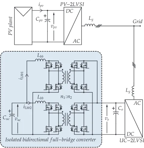
Fig. 1: Proposed central inverter PV configuration with additional energy storage system.
All the mentioned PV curve scan methods suffer from
wide variations in the array power which might be prohibited.
Indeed, limitation of the PV power variability recently appeared
in the regulations [12]. The first country to impose this
limitation was Puerto Rico, setting the maximum allowable
power variation to 10% of the nominal power per minute
[12]. That limitation comes from the fact that the PV power
fluctuation can affect the power quality and reliability of the
system, power fluctuations shorter than 10 min being typically
absorbed by the grid as frequency fluctuations. This issue is
of special importance especially in small grids, such as islands
with high PV penetration rates, because the smoothing effect
from the aggregation of geographically dispersed PV plants is
intrinsically limited, therefore justifying those constraints [12],
[13]. In this work, a maximum allowable power fluctuation up
to 10% of the (nominal) power is considered.
In order to enable the search of the global MPP through a scan of the PV curve, and by the same time meet power fluctuation
limitations, the hybridization of the PV central inverter with a storage element is proposed in this paper and is developed as
follows. Section II describes the proposed hybrid system. The MPPT control of the PV plant and the energy management are
discussed, and the storage element sizing is detailed. Simulation results are provided in section IV in order to validate the
behavior of the proposed hybrid system. Finally section V gives the conclusions of this work.
II. SYSTEMDESCRIPTION AND MODELLING
A PV system formed by a PV plant and a central inverter configuration is considered, as shown in Fig. 1. For simplicity, a
two level voltage source inverter (2LVSI) is chosen as the central inverter topology.
The required storage capability is provided by an ultra-capacitor bank (UC). In order to interface the UC to the grid, a
two stage configuration is used. The first stage is formed by an interleaved bidirectional full-bridge (FB) DC/DC converters.
The FB converter model and its detailed modulation scheme will be given the final paper. The second stage is composed of a
conventional DC/AC 2LVSI.
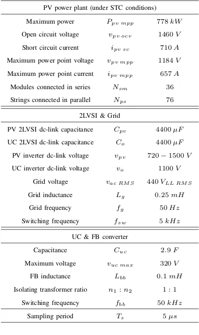
The PV plant is designed considering Canadian Solar CS6X-325P-FG high isolation PV modules (1.5kV) [14]. GE
Pro-Solar PSC-800 MV-L-QC central solar inverter [15] is selected as guide line for both 2LVSI parameters. A320V UC bank is
used as energy storage element. Sizing of the UC is describes in subsection III-A. Table I shows parameters of the considered
system.
TABLE I: Configuration parameters.
PV power plant (under STC conditions)
Maximum power Ppv mpp 778kW Open circuit voltage vpv ocv 1460V Short circuit current ipv sc 710A Maximum power point voltage vpv mpp 1184V Maximum power point current ipv mpp 657A Modules connected in series Nsm 36 Strings connected in parallel Nps 76
2LVSI & Grid
PV 2LVSI dc-link capacitance Cpv 4400µF UC 2LVSI dc-link capacitance Co 4400µF PV inverter dc-link voltage vpv 720−1500V UC inverter dc-link voltage vo 1100V
Grid voltage vac RM S 440VLL RM S Grid inductance Lg 0.25mH Grid frequency fg 50Hz Switching frequency fsw 5kHz
UC & FB converter
Capacitance Cuc 2.9F Maximum voltage vuc max 320V FB inductance Lbb 0.1mH Isolating transformer ratio n1:n2 1 : 1
Switching frequency fbb 50kHz Sampling period Ts 5µs
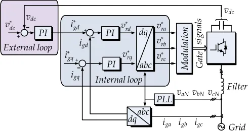
PV plant system has a conventional Voltage Oriented Control
(VOC), as shown in Fig. 4a. The dc-link voltage reference (vpv∗ ) is given by a MPPT algorithm, which is described in subsection
III-A. In VOC scheme q-axis current reference is set to zero,
to generate unitary power factor.
The UC-2LVSI has only the inner current loop of a VOC
scheme. The d-axis current reference (i∗gd) is proportional to a power reference P, as seen in Fig. 4b, i∗gd = k·P where k= 2/(3·vgd), wherevgdis the d-axis grid current. The power
referenceP, corresponds toPuc−P¯pv+Ppv, whereP¯pv, Ppv
are respectively the average and instantaneous PV plant power.
Puc is generated through an external loop, described in section
III-A; which depends upon the state of MPPT algorithm. The
q-axis current reference (i∗gq), proportional to the reactive power, is set to zero. Dc-link voltage (vo) control if performed by the
FB converter control scheme.
Fig. 2: Charging state UC power reference.
Fig. 3: PV voltage reference for the scanning process of the global MPPT.
Control strategy for FB converters is shown in Fig. 4c.
The external PI controller manages the dc-link voltage (vo),
generating the current reference (i∗LBBx, x={1,2}) for both FB. Since each FB converter handles half the UC current,
the reference is divided by 2 (n = 1/2). The inner loop
manages the current trough both inductors (Lbb), generating
the modulation index m˜. The modulation index is limited to
[image:3.612.48.250.78.418.2]+
-+
+
-(a) PV plant 2LVSI control scheme.
(b) External UC-2LVSI reference.
+
-+ +
+
[image:4.612.52.298.58.188.2](c) Full bridge control scheme. Fig. 4: Control schemes.
Afterwards the modulation index is fitted to generate a symmetric voltage wave form in the transformer. FB PWM carriers
operate withπ/4rad/sphase shift, in order to reduce voltage ripple on the UC.
A. Global MPPS algorithm
In [9] it is proposed to reduce the voltage range for the scanning part of the global MPPT search, hence reducing the energy
lost during this process. It is shown in [9] that the search range can be limited to[vmin, vmax]withvpv min=Pmppk−1/ipv scstc
andvpv max= 0.9·vpc ocv.
Implemented MPPT algorithm has two operating states, PV characteristic scan and standard P&O [16]. Scanning is performed
when a certain time elapses since the last scanning execution (for slow power variations), or if the PV plant output power has
a time variation greater than a certain value (for fast power variations). Fig. 3 shows the global maximum power point scan,
wherevpv is variated fromv∗pv(t0)tov∗pv(t3). The voltage scan allows to find the voltagevpv generating the maximum power.
After full scanning, maximum power matching voltage is selected as new voltage reference.
In order to size the UC bank, a scan on the PV curve is considered, while the hole plant is kept operating under STC
conditions. The dc-link voltage swappingvpv generates a PV plant output power variation. The difference between the average
PV plant output power prior to the scanning and the PV plant output power during the scan is calculated and integrated. The
result correspond to the energy loss during the scanning process (Eloss kW h = 20W h), this corresponds to 0.0027% of the
total PV plant power generated in an hour (Epv kW h= 750kW h). The required energy storage element is chosen to have a
voltage range from 300 to100V and a capacity ofCuc= 2.9F, providing an energy storage capacity of32W h.
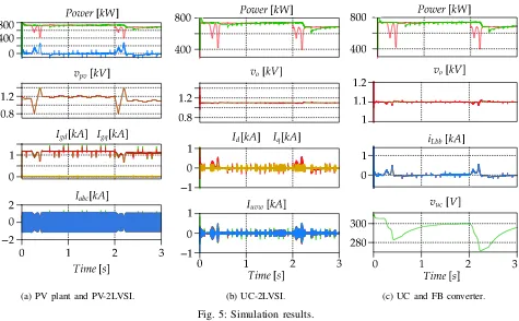
IV. SIMULATIONRESULTS
Two scans are performed, the first one is time triggered (at t= 0.1s) and a second one is triggered by a solar irradiation
change (at t = 2s). Fig 5a shows the PV plant 2LVSI waveforms, in order to perform the scan, the voltaje is swapped as
previously described. Once the scanning ends the new voltage value (vpv∗ ) is set as reference and the system returns to P&O strategy. P&O classic voltaje steps are visible when the system is not performing the scanning procedure.
The behavior of the UC 2LVSI is shown in fig. 5c. The top graphic shows the output powers of the PV plant, energy storage
configuration and the overall output power. The dc-link voltaje vo is controlled by the FB converter. The currents in the d
(a) PV plant and PV-2LVSI. (b) UC-2LVSI. (c) UC and FB converter. Fig. 5: Simulation results.
power reference (P) has two states, scanning and P&O. During scanning the power reference is calculated as the difference
between the PV plant average power (Pavg), calculated during the P&O period, and the current PV power(Ppv). During P&O
the power reference is calculated through the vuc vs P curve, shown in Fig. 2. Line currents and d-axis current reflect the
power referenceP.
FB converter and UC waveforms are displayed in fig 5c. On the top graphic both, PV-2LVSI and total system output power
are shown. The total system output power variation does not exceed the 10% nominal power (75W), despite the power variation
of the PV output power. Further details will be given in the final version of the paper.
UC-2LVSI dc-link voltaje reference vo∗ is kept constant at 1100V, vo is regulated through the management of both FB
converter inductance currents (iLbb1 andiLbb2). The voltage on the UCvuc, depends upon the MPPT state. When performing
scan, energy will be drawn from the UC, hence reducing its voltage, on the other hand when P&O acts, energy is injected from
the grid towards the dc-link Co and afterwards to the UC. Since power provided by the UC bank has a small time duration
(0.1s), the UC-2LVSI may be derated.
V. CONCLUSION
This paper presents a large-scale central inverter PV plant, hybridized with an UC bank. The additional energy storage
capability allow a PV plant with central inverter configuration to perform a global maximum power point tracking, repecting
power limitation imposed by legislation at 10% of the nominal power per minute. The additional energy storage capability can
also be used to provide other ancillary services, this matter being the scope of a future work. The proposed system has been
presented considering a single central PV inverter. Still, the proposed hybrid system can be though at larger scale, employing
a single ultra-capacitor power system at the plant level with various central PV inverters performing the scanning sequentially,
REFERENCES
[1] S. Kouro, J. Leon, D. Vinnikov, and L. Franquelo, “Grid-connected photovoltaic systems: An overview of recent research and emerging pv converter
technology,”IEEE Ind. Electron. Mag., vol. 9, no. 1, pp. 47–61, March 2015.
[2] H. Renaudineau, A. Houari, J.-P. Martin, S. Pierfederici, F. Meibody-Tabar, and B. Gerardin, “A new approach in tracking maximum power under
partially shaded conditions with consideration of converter losses,”Solar Energy, vol. 85, pp. 2580–2588, 2011.
[3] Q. Duan, J. Leng, P. Duan, B. Hu, and M. Mao, “An improved variable step po and global scanning mppt method for pv systems under partial shading
condition,” inIntelligent Human-Machine Systems and Cybernetics (IHMSC), 2015 7th International Conference on, vol. 1, Aug 2015, pp. 382–386.
[4] B. N. Alajmi, K. H. Ahmed, S. J. Finney, and B. W. Williams, “A maximum power point tracking technique for partially shaded photovoltaic systems
in microgrids,”IEEE Transactions on Industrial Electronics, vol. 60, no. 4, pp. 1596–1606, April 2013.
[5] K. Itako, “Pcs with scanning-type mppt control for industrial grid-connected pv power generation system,” in2014 International Power Electronics
Conference (IPEC-Hiroshima 2014 - ECCE ASIA), May 2014, pp. 3244–3248.
[6] H. Renaudineau, F. Donatantonio, J. Fontchastagner, G. Petrone, G. Spagnuolo, J.-P. Martin, and S. Pierfederici, “A pso-based global mppt technique
for distributed pv power generation,”IEEE Trans. Ind. Electron., vol. 62, no. 2, pp. 1047–1058, Feb 2015.
[7] R. Kot, S. Stynski, and M. Malinowski, “Simple scanning methods for a global-mpp determination in a pv string,” inSelected Problems of Electrical
Engineering and Electronics (WZEE), 2015, Sept 2015, pp. 1–6.
[8] K. Chen, S. Tian, Y. Cheng, and L. Bai, “An improved mppt controller for photovoltaic system under partial shading condition,”IEEE Transactions on
Sustainable Energy, vol. 5, no. 3, pp. 978–985, July 2014.
[9] M. Boztepe, F. Guinjoan, G. Velasco-Quesada, S. Silvestre, A. Chouder, and E. Karatepe, “Global mppt scheme for photovoltaic string inverters based
on restricted voltage window search algorithm,”IEEE Transactions on Industrial Electronics, vol. 61, no. 7, pp. 3302–3312, July 2014.
[10] E. Koutroulis and F. Blaabjerg, “A new technique for tracking the global maximum power point of pv arrays operating under partial-shading conditions,”
IEEE Journal of Photovoltaics, vol. 2, no. 2, pp. 184–190, April 2012.
[11] K. Ishaque and Z. Salam, “A deterministic particle swarm optimization maximum power point tracker for photovoltaic system under partial shading
condition,”IEEE Transactions on Industrial Electronics, vol. 60, no. 8, pp. 3195–3206, Aug 2013.
[12] J. Marcos, O. Storkl, L. Marroyo, M. Garcia, and E. Lorenzo, “Storage requirements for{PV}power ramp-rate control,”Solar Energy, vol. 99, pp. 28
– 35, 2014. [Online]. Available:http://www.sciencedirect.com/science/article/pii/S0038092X13004672
[13] National Renewable Energy Laboratory (NREL). (2013) Review of PREPA Technical Requirements for Interconnecting Wind and Solar Generation.
[Online]. Available:www.nrel.gov/docs/fy14osti/57089.pdf
[14] Canadian Solar. (2016) Canadian Solar, solar panels, CS6X-P-FG. [Online]. Available:www.canadiansolar.com
[15] GE power conversion. (2012) GE power conversion, ProSolar Central Solar Inverter. [Online]. Available:www.gepowerconversion.com
[16] P. Bhatnagar and R. Nema, “Maximum power point tracking control techniques: State-of-the-art in photovoltaic applications,”Renewable and Sustainable