See discussions, stats, and author profiles for this publication at: https://www.researchgate.net/publication/314184991
Optical difference engine for defect inspection
in highly-parallel manufacturing processes
Conference Paper · March 2017
CITATIONS
0
READS
129
4 authors:
Some of the authors of this publication are also working on these related projects:
Modern Methods for Measuring the Functional Characteristics of SurfacesView project
Multi-sensor metrology for microparts in innovative industrial productsView project Xiaobing Feng
University of Nottingham 12 PUBLICATIONS 3 CITATIONS
SEE PROFILE
Rong Su
University of Nottingham 15 PUBLICATIONS 25 CITATIONS
SEE PROFILE
Mingyu Liu
The Hong Kong Polytechnic University 12 PUBLICATIONS 4 CITATIONS
SEE PROFILE
Richard Leach
University of Nottingham 295 PUBLICATIONS 1,764 CITATIONS
SEE PROFILE
All content following this page was uploaded by Richard Leach on 20 March 2017.
Laser Metrology and Machine Performance XII
Optical difference engine for defect inspection
in highly-parallel manufacturing processes
Xiaobing Feng
1, Rong Su
1, Mingyu Liu
2, Richard Leach
11The University of Nottingham, United Kingdom
2The Hong Kong Polytechnic University, Hong Kong
Abstract
Traditional defect inspection for highly-parallel manufacturing processes requires the processing of large measurement datasets, which is often not fast enough for in-situ inspection of large areas with high resolution. This study develops an all-optical difference engine for fast defect detection in highly-parallel manufacturing processes, where the detection of defects (differences from nominal) is performed optically and in real-time. Identification of defects is achieved through an optical Fourier transform and spatial filtering, detecting differences between two real objects by nulling information that is repeated in each object. The developed prototype device is demonstrated using geometric patterns of similar scale to components in printed electronic circuits.
1
Introduction
Laser Metrology and Machine Performance XII
image stacks, and currently the data processing speed is too slow for in-situ defect inspection in HPM processes. Optical processing is an alternative to digital processing because it offers greater speed. Parallel optical processing by use of frequency domain architectures is potentially very fast, but often lacks flexibility and accuracy. The joint-transform correlation technique has been demonstrated as a useful tool for identifying defects in fabrics and optical fibres [9,10]. The coherent optical processing technique based on spatial filtering also offers high speed feature comparison and may be used for defect inspection in HPM [11]. In this paper, an optical difference engine (ODE) is developed using coherent optical processing techniques and demonstrated using simple geometries.
2
Principles and sensitivity analysis
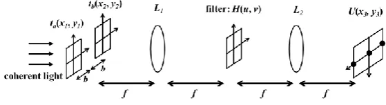
Some types of signal computation, e.g. autocorrelation, spatial filtering, can be performed optically using Fourier optics in real-time. Utilising this advantage, the ODE is able to compute the difference between a perfect reference object and a test object with defects at high speed. A simple illustration of an ODE is shown in Figure 1. Two objects (ta and tb) positioned side by side are illuminated
[image:3.595.107.387.386.462.2]with coherent light and imaged with a 4f-system. An optical grating is placed at the H plane, where the real-space image of the two objects is transformed into the Fourier space. The grating performs spatial filtering in the Fourier plane before the image is transformed back into real space at the U plane, where the images of the two objects are overlaid and all the information repeated in both images is nulled, resulting in a single image containing only the difference between two objects.
Figure 1: Illustration of an optical difference engine
A detector can be placed at the U plane to record the difference. As subsequent computation is kept to a minimum, the inspection speed is potentially close to the detector speed.
Laser Metrology and Machine Performance XII
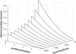
Figure 2: Allowed error in the grating period for the maximum central shift of 5 μm, assuming wavelength 𝜆 = 0.5 μm
3
Prototype optical difference engine
In order to implement the ODE without resorting to costly components, off-the-shelf products were used to build the prototype device. Table 1 lists the specifications of the core optical components in the prototype ODE system.
Table 1: Specifications of the optical components in the prototype ODE
Laser wavelength/nm 532 Laser beam diameter/mm 3.5
Grating type blazed Grating period/µm 3.33
Imaging lens focal length/mm
30 Image sensor type CMOS
Image sensor colour monochrome Image sensor pixel size 1280 × 1024
[image:4.595.112.392.522.576.2]Several practical challenges arose when building the prototype: (1) lack of suitable sinusoidal grating led to the use of a blazed grating with a saw-tooth shaped grating profile; the presence of blaze angle resulted in a refracted light path; (2) beam intensity homogeneity and dust on the built-in optics; (3) collimation quality of the light beam after expansion; (4) diffraction around the edges of the objects; and (5) compromise between lens size (cost) and effective field of view. These challenges were addressed by additional components and deviating from the setup in Figure 1. For example, a pinhole was used to improve the light intensity homogeneity and reduce speckle resulting from dust; the camera and imaging lens were re-positioned to comply with the modified light path due to the blazed grating; and the offset distance between the two objects was adjusted to compensate for manufacturing and alignment error in the grating. Figure 3 shows the setup of the developed prototype device.
Figure 3: Setup of the prototype ODE system
Laser Metrology and Machine Performance XII
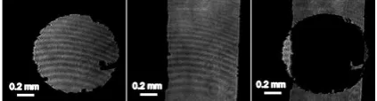
[image:5.595.141.353.109.166.2]HPM processes. Small defects are present on the edges of both patterns as seen in the figure.
Figure 4: Inspection result comparing a rectangular bar with a hole. Images of a hole of Φ1 mm (left), a rectangular bar of 0.8 mm width (middle) and the optical
difference of two objects (right).
In the resulting difference image, the common area present in both objects is nulled and shown as a dark area. The geometrical irregularities on the edge of the circular and rectangular patterns can be observed, as well as misalignment of the two patterns’ centres. Defects as small as 30 μm can be detected.
4
Conclusion
An ODE system has been developed and implemented using off-the-shelf components and demonstrated with geometric patterns cut from a thin sheet. Preliminary result suggests that 2D ODE is a promising tool for the high resolution defect inspection in HPM processes. Data post-processing is minimised by conducting optical processing and the speed of the ODE is potentially limited by the sensor acquisition time. Further research efforts will focus on a parallel sensor setup to inspect larger areas and improvement of imaging quality.
Acknowledgement
This study was funded by the EMPIR programme co-financed by the Participating States and from the European Union’s Horizon 2020 research and innovation programme through the project 14IND09 MetHPM. The authors would like to appreciate the support of Mr. Majdi Salman (Cardiff University) and Prof. Jian Liu (HIT, China) for their work on the mathematical simulation of the ODE.
References
1. O’Connor D, Henning A J, Sherlock B, Leach R K, Coupland J, Giusca C L 2015
Appl. Opt.54 8872-8877
2. Zhang L, Ume I C, Gamalski J, Galuschki K P 2006 IEEE Transactions on Components and Packaging Technologies29 13-19 3. Loh H H, Lu M S 1999 IEEE Transactions onIndustryApplications 35(2) 426-432 4. Kim T H, Cho T H, Moon Y S, Park S H 1999 Pattern Recognition32 565-575 5. Chiou Y C, Liu J Z, Liang Y T 2011
Sensor Review31 154-165
6. Pollard H E, Neff R E, Ajluni C J 1994
U.S. Patent 5,334,844
7. Su R, Kirillin M, Ekberg P, Sergeeva E, Mattsson L 2012 Opt. Express20,4603-4618 8. Elrawemi M, Blunt L, Muhamedsalih H, Gao F, Fleming L, 2015 Int. J. Automation Technology9(3) 312-321
9. Liu W, Kim H, Lee S, Lee S 1998 Optical Engineering37 1468-1474
10. Poon T, Qi Y 2003 Appl. Opt.42 4663-4669
11. Lee S H 2014 Optical information processing: fundamentals Springer, Berlin Heidelberg