The Omega Architecture:
Towards Adaptable, Self-Managed Networks
Javier Baliosian, Franc¸oise Sailhan, Ann Devitt, Anne-Marie Bosneag
Network Management Research Centre, Ericsson IrelandAthlone, Ireland
Email:{javier.baliosian, francoise.sailhan, ann.devitt, anne-marie.bosneag}@ericsson.com
Abstract— The tremendous growth in ubiquity and diversity of wireless networks render the exploitation of highly heterogeneous next generation networks more challenging. This complexity is compounded by the highly dynamic nature of many of these network types and exacerbates the demands on the network management system to ensure robust service delivery. Various centralised, distributed or cooperative management systems have been proposed to address these demands. However, an inability to scale in some cases, or weak support for automation and lack of control for operators in others render existing approaches unsuitable for managing networks in a cost-effective way. For this reason, we introduce Omega, a distributed and policy-based network management system with self-configuration capabilities. Every self-ware entity (i.e. network element) in the system is potentially a manager for a set of local (re)configuration tasks or for a sector of the network. The system may dynamically delegate management tasks that are beyond its remit (but necessary in order to achieve its goals) to other entities, re-evaluating this delegation of tasks according to changing topology and connectivity. The scalability of our platform comes from both (i) the minimisation of the traffic generated by management messages (e.g. events and configuration requests) and (ii) the use of a fully distributed discovery mechanism. Similarly, its adaptability is attributed to its capacity to react dynamically and in a timely way to network changes. This capability is provided by a resource discovery protocol that maintains an up-to-date overview of the network and a policy-based manager that exploits static knowledge about network configuration constraints and procedures, learnt information about network behaviour patterns and operators’ strategic business objectives to trigger, execute and adapt configuration tasks to current network conditions.
I. INTRODUCTION
Recent advances in wireless technologies coupled with an abundance of portable devices are opening up exciting opportunities for the future of wireless networking. The proliferation of radio access technologies will lead to the emergence of a heterogeneous and complex communication system spanning a broad spectrum of hardware and software and suffering from increasing signal interference, connectivity variability and changing topology. In this context, robust service provisioning must be supported by powerful network management capabilities. However, given the specific char-acteristics of next generation systems, it appears that the centralised or hierarchical paradigms widely adopted to handle FCAPS (Fault, Configuration, Accounting, Performance and Security) functionality [1] cannot adapt to the demands of future networks. With a constant demand for high availability, centralised approaches are incapable of delivering an
ever-increasing number of management functions from a central entity due to the physical limitations of resources. Early attempts at decentralisation, represented by hierarchical net-work management systems, are inflexible and cannot facilitate dynamic restructuring or reallocation of management tasks to meet network needs.
The inadequacies of these existing approaches have driven a demand for strongly distributed and flexible systems, such as the multi-agent-based systems. The trend is toward fully distributed network management strategies. However, specific challenges are to be overcome. These strategies are resource and bandwidth intensive, complex to implement, and, from the network operator’s perspective, do not provide sufficient network control. Commercial deployment of such systems has, therefore, been very low. The inefficiencies that characterise all existing network management systems, aggravated by the heterogeneity, dynamism and potentially vast dimensions of wireless networks of the future, remain a major obstacle to a more cost-effective exploitation of networks by telecom operators. It is therefore essential to devise management solutions which address existing operator commitments to provide services to users, within a framework that allows greater flexibility and the ability to react in a timely fashion to predictable or unpredictable failures.
tasks, according to constraints imposed by operators’ strategic policies. Section III-C sets out a machine learning module which logs, correlates and summarises over events locally and globally to derive patterns of event activity that can be used to influence policy choices. Section III-D goes on to describe how policy conflicts are resolved and how the stability of this system is enforced by interaction between the policy engine and the behaviour learning module. Finally, in Section IV, a detailed scenario is explored to illustrate the capabilities of the system, while Section V presents our conclusions and future work directions.
II. NETWORKARCHITECTURE
Given the inefficiency (e.g., lack of flexibility, inability to scale, bandwidth gluttony) of existing organisational structures for network management systems, it is mandatory to devise new alternatives that maximise the delegation of management tasks over network elements. However, it is obviously not realistic to assume that a unique organisational structure, whether centralised, hierarchical or fully distributed, could address all the requirements of the wide range of generic network management tasks (e.g., event management, resource discovery and data dissemination). To this end, our approach relies on the three aforementioned basic organisational struc-tures while trying to maximise the distribution of tasks over the nodes. More precisely, we restrict the number of management tasks that are carried out in a centralised way. Then, only the tasks that inherently require an underlying centralised organisation (such as accounting) or those tasks which perform better given a weakly distributed structure (e.g., event and data aggregation) are carried out using an approach which is not fully distributed (Section II-A). Other management tasks, e.g., on-demand discovery of resources (e.g. policies, ontologies) follow a fully distributed approach (Section II-B.3). As cen-tralised network management is a well known approach, in this paper we focus on the semi and fully distributed network management approaches and illustrate our presentation with two case studies: event notification and resource discovery.
A. Semi-Distributed Event Monitoring
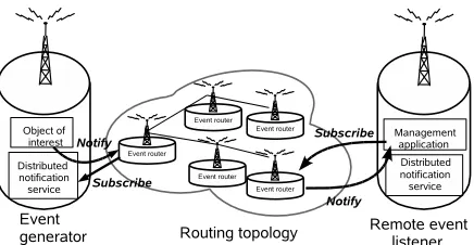
The proposed event monitoring service is responsible for detecting, capturing, aggregating and correlating events from distinct sources (e.g., networked devices, distributed applica-tions or services). These detected events (i.e., notificaapplica-tions and alarms) are classified, filtered and analysed for archiving for further off-line or on-line analysis (see section III-C), for root cause analysis of any critical problem (e.g., fault, security, performance threats) and for triggering reactions (see Section III-B). From a communication point of view, this event monitoring service continuously collects event notifications and control information from monitored agents (also called agents, sources, or producers) and sends them to remote monitoring agents (also called managers, event consumers or listeners). The routing of these generated events is performed by intermediate nodes, calledrouters, that, besides forwarding event notifications and control messages (e.g. event registration
Fig. 1. Distributed Event Notification
and de-registration), also aggregate primitive or composite events so as to reduce the number of transmitted events.
1) Event Communication Model: The proposed event com-munication scheme, illustrated in Figure 1, derives from the well known publish/subscribe paradigm which is composed of three key steps:
• event subscription, made by consumers to agents; • local event collection;
• external notification which consists of transferring a rel-evant message, containing a description of the occurred event, from an agent to a consumer through intermediate routers.
Typically, two approaches can be followed to handle sub-scription and notification. The first consists of publishing events in named channels whereas the second lies in using the contents of the events to allow routers to make forwarding decisions. The flexibility of subject-based systems induced by the absence of agreement between consumers and sources concerning the channel(s) to use, dictated our decision to use a subject-based system in which subscriptions identify a class (also called type) of events belonging to a given subject and are used to forward messages intelligently by routers.
2) Subscription Management: Event monitoring starts when a consumer expresses its interest in receiving particular types of events. In practice, this consumer (e.g., a network management application) specifies its monitoring demand by sending a subscription that encompasses a set of primitive event specifications. When an event occurs, this event is caught locally and then disseminated based on the instructions provided during registration.
3) Local Event Notification: Event collection and notifi-cation is performed locally and globally by a notifinotifi-cation service. In order to accommodate the broad range of event sources and the resulting control and monitoring information (e.g., host, application, hardware, machine, network, link), this notification service derives from two distinct standards:
[image:2.612.329.547.51.164.2]notification is the SNMP agent that is responsible for (i) collecting and storing the network management related information that is expressed in the MIB (Management Information Base) model and (ii) originating SNMP traps (i.e., event notifications) and passing them to the local notification service through an adaptor;
• the traditional java component event model that propa-gates locally the events issued by any local java object included in the application in question.
In practice, an event notification is generated locally whether by a SNMP agent or a java object and is transformed into a common format before being disseminated over the network. This notification object incorporates the following key components: (i) an identifier of the event,1 (ii) a reference
to the object and to the host that generated the event so as to guarantee the uniqueness of event signatures across objects belonging to the computing network, (iii) an event type and sub-type(s) followed by a collection of attribute-value pairs2 that characterise the event. The events expressed
in the above format are then disseminated based on the event communication model described below.
Our approach to route notifications between consumers, routers and producers in a scalable way relies on a grouping protocol that clusters subscribers interested in a particular class of event with the publishers that generate it. To ensure a fair distribution of the routing tasks while supporting minimal event propagation, event classes (and the related filters) may be decomposed into sub-classes and assigned to alternative groups for routing. Conversely, in order to limit the number of groups created, transient or long-lived sub-groups may be created. In this case, the event notifications are not propagated to the overall group. Indeed, to support efficient event forward-ing into these sub-groups, each intermediate router manages a routing table that contains information concerning the event messages that should be forwarded to neighbouring routers and consumers. To address scalability and performance issues, agents rely on group communication to exchange both event and control information over these sub-groups or groups.
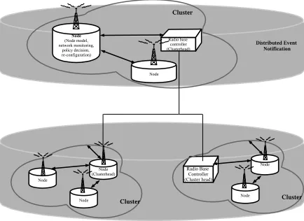
4) Group Communication for Event Routing: As illustrated by Figure 2, our semi-distributed organisation structure is based on a backbone of nodes that are selected so as to perform routing, storage or control functionalities on local nodes and therefore keep to a minimum the traffic induced by self-management tasks. These backbone nodes are also responsible for cooperating with each other to perform distributed event management over the whole network. The backbone creation and maintenance is dynamically carried out by a group man-agement strategy that (i) includes a clustering algorithm that locally groups nodes under the responsibility of a particular node called cluster-head or super-peer and (ii) connects the cluster-heads in a distributed and scalable way so as to form
1This identifier refers to the Object IDentifier (OID) of a MIB variable or
event identifier provided by the java platform.
2This set of attribute-value pairs derives from the selection and extraction
of the corresponding variables from either the MIB tables or the java-object state.
Fig. 2. Underlying Organisational Structure for Event Notification
an overall backbone. Nodes communicate symmetrically (i.e., as peers) over a routing backbone structured as an undirected acyclic graph. One of the key benefit of this organisation, in contrast with a hierarchical approach, is the fair distribution of load among routers and the low impact of a router dis-connection on event delivery. Network management tasks are executed on top of this self-configurable group management service that deals with network characteristics, such as dynam-icity, network element connectivity. A similar strategy is used to deal with deployment of policies and ontologies and the routing of events and remote actions.
B. Resource Discovery
The resource discovery methods employed take into account the properties of the system: very large size, dynamicity, and heterogeneity. As noted above, centralised approaches are not suitable for such systems. Therefore, we propose a discovery mechanism based on Distributed Hash Tables (DHTs), which offers a scalable and efficient way of locating nodes and services in the system.
DHTs [2], [3], [4], [5] have appeared as a structured mechanism for locating data in peer-to-peer systems, when it became clear that flooding is neither an efficient mechanism, nor a reliable one as it is bandwidth intensive and does not guarantee that the required data will be found. They create an overlay on top of the physical network, and have a built-in efficient mechanism for scalable routing. DHTs offer many beneficial properties, such as load-balancing, self-configuration, adaptivity in response to nodes leaving and joining the system, fault-tolerance and ease of deployment. There exist many variations of DHTs, but most of them offer routing/location algorithms of complexity O(logN), whereN
is the number of nodes in the system. The cost in terms of state data that must be stored at each node is also O(logN). The routing algorithm relies on a converging mechanism, which ensures that the routing messages get one step closer to the target at each routing step, by matching increasingly longer prefixes between the visited nodes and the target node.
[image:3.612.329.546.55.213.2]are based on Pastry [3]. Pastry is one implementation of DHTs that offers increased routing efficiency due to the fact that it takes into account node distance (as provided by the underlying layer) when creating the overlay, and it provides very good load-balancing properties. Three types of resource discovery are provided to the management system:
• discovering individual nodes,
• discovering sets of nodes that have a common property (e.g., abide by the same policy),
• discovering sets of nodes offering a specific set of ser-vices.
1) Discovery of individual nodes: This type of discovery is used by administrators and other nodes, when they know which node they need to contact. Similar to Pastry, each node in the network is assigned an ID, which is the result of applying a hash function on its unique device ID in the telecom network. The Pastry routing protocol ensures that any node in the network can be quickly located from any other point in the network, by sending a routing message to the corresponding nodeID. This provides administrators and other nodes the facility to efficiently locate nodes whose IDs they know. This in turn facilitates administrative tasks that are already in place today, such as checking for data inconsistencies between two nodes selected from the network.
2) Discovery of sets nodes with common properties: For discovering nodes with common properties, such as nodes that abide by a common policy, the nodes are structured into a multi-layer DHT, each layer being organized as one DHT and containing nodes with a common property. This method is based on previous work [6], in which sets of nodes that provide the same consistency are grouped into a common DHT. The nodeID is extended to contain an additional part, which encodes the various properties of interest to us. The multiple DHTs are linked together throughconsistency neighbour links, and an adequate protocol exists for dynamically refreshing these links. It has been shown in [6] that the discovery and self-configuration protocols are scalable, fault-tolerant and efficient.
3) Discovery of services: A different type of functionality is required for locating services in the network. To provide this function, nodes must advertise the services they offer. Advertising means associating an ID with the service (e.g., a hash on the service name), and sending a record of the form {nodeID, serviceID} to serviceID. This will ensure that the node whose ID most closely matches the serviceID will store the record. For fault-tolerance reasons, the record will also be cached on the leafset of the node. The leafset contains nodes that are close to the current node in the overlay, i.e., they have IDs that are numerically close to the ID of the current node.
When a query is issued, it is first decomposed into a set of queries for individual services. Then messages are sent through the network to discover the IDs of the nodes that offer each service. Finally, an intersection over the individual sets of node IDs is performed – the result contains the nodeIDs of the nodes that offer the required set of services. These nodes can then be contacted to provide the services needed.
The method proposed for service discovery is similar to the one used in [7]. Its application to the management of telecom networks is novel, and future work includes the combination of this protocol with protocols for caching along the route and for agreement between replicas [8], [9], which will prevent overloads of nodes storing records for popular services and will ensure fault-tolerance in face of frequent joining/leaving events, respectively. Future work also includes optimisations that take into account the large number of records that may have to be stored at nodes or processed during the query process.
III. NODEARCHITECTURE
Current trends to reduce OPEX for network management illustrate that the network cannot rely on human intervention for all configuration and maintenance activity for reasons both practical (the size of the task is becoming insurmountable) and monetary (the cost of the activity does not justify the returns). The distributed network organisation outlined above presupposes a degree of autonomy in the network nodes to manage themselves in a fully or partially distributed environ-ment. From a node perspective, the nodes must be empowered to perform at least some configuration and maintenance tasks. The ability to perform these tasks comprises several aspects:
• a node must be capable of carrying out the actions that the task implies;
• a node must decide when it is appropriate or necessary to carry out such a task;
• a node must continue to make appropriate decisions even if the context of its deployment changes, that is, it must adapt to changes in its environment.
The first two aspects are acknowledged necessary components of any even partially autonomous system. The third aspect, adaptability, is very important in the highly dynamic world of wireless communication, perhaps less important for less dynamic fixed line networks.
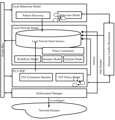
Fig. 3. Node Architecture
by monitoring the effects of configuration actions over long timescales (section III-C) and adapting policy decisions on the basis of observed effects (section III-D).
We propose the self-ware node architecture, presented in Figure 3, to provide this adaptive self-configuring functional-ity. The following sections outline the components of this self-ware architecture and how the components interact to achieve stable, adaptive self-management.3
A. Automating actions: Local Network Model
The Network Model, based on work presented in [10], is an ontology-based enhanced Management Information Base (MIB). A formal ontology is a taxonomy of concepts and their attributes in a given domain together with a formal representation of domain assumptions which is semantically rich and based on a well-defined logical paradigm, such as Frame Logic [11]. The purpose of employing an ontological representation is to capture concepts in a given domain in order to provide a shared common understanding of this domain, enabling interoperability and knowledge reuse but also machine-readability and reasoning about information through inferencing. The Local Network ontology model stores a node’s current configuration, its relationships with other objects in the network and constraints on its possible configuration imposed by the hardware and software deployed on the network element. It also stores the workflows associated with configuration tasks, i.e., the sequence of actions affecting a network element that need to be completed in order to fulfil a given task. Once a workflow is triggered by a policy decision,
3The Event Bus component in the figure is the local realisation of the
semi-distributed event management component discussed in Section II-A and will not be discussed further in this section. The Enforcement Point component is the interface to the Network Element itself and will also not be elaborated upon here.
the inference engine begins to execute the actions of the work-flow sequence in turn. These actions can be events triggering other workflows, updates to the current configuration model or the action may be to wait for other events with information or acknowledgements required for the completion of the original configuration task. The Network Model therefore is both a passive information repository and an active propagator of change to this repository.
Each node in an Administrative Domain has its own Local Network Model instance storing its own current configuration, constraints and relationships. The sum of these local models is a Global Network Model. Since the Local Network Model instances are not necessarily consistent with each other, the Global Network Model instance may be internally inconsis-tent. Nodes will continuously interact to store and update shared entities, such as links and VPNs, by means of events and event subscription in order to converge their views without any requirement to achieve complete consistency. The trade-off between perfect consistency and traffic overhead is governed by consistency mechanisms that are outside the scope of this paper.
B. Taking decisions: Policy Decision Point
Within this framework, policies are implemented as condition-action rules where the condition may be the oc-currence of some events (e.g.,an alarm or a service request), in a certain network state and the action is the desired response to that condition event, as defined by the operator. The Policy Model in this self-ware architecture is based on a classic Policy Decision Point (PDP) [12], which subscribes to events through the event notification service and evaluates the policy conditions using the information stored in the Network Model. Based on this, the PDP decides whether a policy condition has been met and therefore the attendant reconfiguration action(s) must be performed. In practice, if the conditions of a given policy are met, the PDP instigates the necessary changes by issuing a workflow-triggering event to the Local Network Model which then begins to execute the relevant workflow propagating the necessary changes in the Local Network Model and to the Network Element itself. The reconfiguration action may also involve other network elements, in which case the node may be the manager of the activity and delegate responsibility for some actions to other nodes or it may delegate management of the task to another node. Section IV outlines how this functions for a standby-link configuration task.
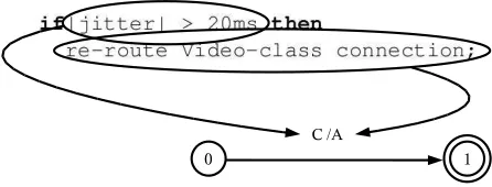
The ensemble of local policies is modelled using a special kind of finite state machine, presented in [13], called a Finite State Transducer extended with Tautness Functions and Identities(TFFST). These machines are graphs with two labels on each edge, one expressing an input symbol and another specifying an output symbol. For a simpleif-thenrule:
if|jitter| > 20 ms then
re-route Video-class connection;
[image:5.612.61.288.50.286.2]Fig. 4. Correspondence between if-then constituents and FST elements.
about jitter for one connection and, depending on this value, produces a certain re-routing action. This is illustrated in Figure 4. The TFFST has only one edge, its input label represents the type of event the rule is expecting (i.e., jitter) and the condition that this must fulfil (i.e., the jitter value) and the output label the output action that must be performed.
This model exhibits good performance for policy evaluation. It is also oriented to the resolution of policy conflicts as each condition and action has an associated Tautness Function which can be applied to select between two conflicting poli-cies. Tautness Functions are generally based on criteria, such as specificness of the policy condition or cost of the policy action, and provide a means of evaluating the appropriateness and effectiveness of applying a given policy. In fact, the concept of a tautness function for conflict resolution provides a very flexible means of influencing policy choices in the PDP. The PDP provides the ability to take decisions. The ability to adapt these decisions to current network conditions is a more complex task which involves maintaining awareness of network context and providing a point of interaction between this context awareness and the policy decision point. The context awareness component, i.e., the Behaviour Model, is outlined in the following section. The point of interaction, the dynamic conflict resolution component, is outlined in section III-D.
C. Learning from experience: Behaviour Model
In a distributed self-managed network such as this one, the network devices perform independent actions, i.e. exhibit individual behaviour, in order to fulfil services and meet user requirements. This individual, independent behaviour may affect the network as a whole. Therefore, in order to detect and possibly predict behaviour that will adversely affect the provision of services and the experience of end users, it is critical to observe the behaviour of individual nodes and aggregate this to observe the behaviour of the network as a whole. Performance and fault monitoring, monitoring how a network is doing, are standard network management tasks in any current network. In addition to monitoring the node or network status (i.e. how it is doing), a management system may also monitor the node or network activities (i.e. what it is doing). In order to be useful, the management system should infer how what the node or network is doing impacts on how it is doing. Ideally, the management system should also extrapolate what may happen in the network based on
knowledge about what has happened in the network in the past. The Behaviour Model component of this Self-Ware Node architecture is designed to carry out these monitoring, correlation and prediction functions.
The internal representation of the Behaviour Model is a Dynamic Bayesian Network (DBN) [14]. Bayesian Networks (BN) [15] are state-of-art technology for monitoring different types of behaviour, for example power consumption of ma-chines [16] or fault diagnosis in industrial processes [17] by specifying the dependencies (and independencies) that hold between aspects of a system, in this instance, events in a network. BNs consists of a Directed Acyclic Graph (DAG) structure, where the nodes represent variables from an appli-cation domain, in this case events in a network (parameters, alarms, configuration requests), and the arcs represent the influential relationships between them, for example a drop in parameter X triggers alarm Y. Additionally, there is an asso-ciated conditional probability distribution over these variables which encodes the probability that the variables assume their different values given the values of their parent variables in the BN. For example, the probability of alarm Y being triggered when parameter X is above a given threshold is 1. The probability distribution can be assigned by an expert or learnt off-line from historical data or learnt on-line incrementally from a live feed of data. In the Behaviour Model described here, the probability distribution is learnt incrementally on-line for each network device from the event activity of that network device. Figure 5 shows part of a sample Bayesian Network for the telecommunications network domain. It consists of a network Key Performance Indicator (KPI), the performance counters which contribute to that KPI and a service workflow which is triggered by degradation in the KPI levels.
Time in Bayesian Networks is implicitly represented by the arcs of the model which denote a causal relationship. Dynamic Bayesian Networks add an explicit temporal dimension to traditional BNs. They are a generalisation of Bayesian Net-works that explicitly model changes in the model over time with additional temporal arcs. The Behaviour Model described here exploits this temporal dimension to ensure the sequential nature of events is explicitly captured in the model.
Fig. 5. Sample Bayesian Network composed of network event types
D. Adapting to change: Dynamic Conflict Resolution
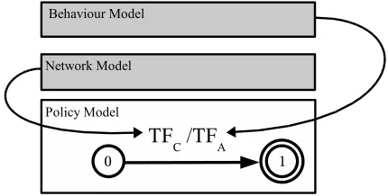
The interaction between the decision-making PDP and the event-monitoring BM occurs at the Dynamic Conflict Reso-lution component. As the name suggests, this component is designed to resolve any conflicts that arise between policies at run-time. The TFFST-based policy model is the union of multiple individual policies and any static conflict between these policies will have been resolved at compilation of the TFFST, most of them automatically and when this is not possible by a human. However, at run-time, other conflicts may occur between policies which could not be detected at compilation time as they arise from the current status of the network. In such instances, the policy engine has evaluated the conditions of its local policies and two or more policies could be triggered by the same recent events. The PDP must decide between these policies and apply the most appropriate to current circumstances. In a classic PDP, the engine applies a system of priorities associated with each policy in order to select between them. Tautness functions, as discussed in Section III-B, are a more dynamic way of prioritising policies, but they are still defined as functions encoded off-line (before policies are deployed) and may not encode the experience of the working system. The Dynamic Conflict Resolution component of this self-ware node architecture, is designed to adapt these Tautness Functions to current network conditions by incorporating the probabilities of event occurrences derived from the Behaviour Model component. Tautness Functions are metric functions defined over policy conditions and actions; given a network state, they evaluate to a value between -1 and 1; positive values correspond to the condition evaluated as
trueand negative values to conditions evaluated asfalse. When the PDP evaluates a TF for a specific policy condition it does it using the network state encoded in the Network Model (NM). Once the set of possible actions to trigger is identified (because their respective conditions have positive TFs) the Dynamic Conflict Resolution component computes
Fig. 6. Condition TF and Action TF are Computed using the Network Model and the Behaviour Model Respectively
the probability for the system’s goal4encoded in the Bayesian
network and uses that value as the TF for the actions. In this way, each conflicting policy is associated with a final numerical value based on the condition TF computed using the network state represented by the NM and a predicted estimate of policy effects expressed by theaction TFcomputed using the knowledge in the BM (see Figure III-D), then the conflict can be resolved as usual. This process maximises the probability of reaching the system goal given policies of varying specificity.
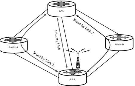
IV. ANEXAMPLE: DYNAMICSTANDBYLINK In a 3G network, a Radio Network Controller (RNC) node is connected to many Radio Base Station (RBS) nodes in a “parent-son” relationship by a primary link and a secondary standby link. Traditionally thestandby linkis a second physical connection which is configured when the network is rolled out. The scenario described here represents a hypothetical network management function in a 3G telecommunications network to configure standby links dynamically according to network demands rather than statically at network roll-out
4One system goal might be, for example, to have a balanced network
[image:7.612.142.484.58.219.2] [image:7.612.329.544.271.380.2]Fig. 7. Standby Link Scenario Network Schema
time. This function is potentially very useful as standby links reserve specific resources in the nodes they connect and also in any node that cross-connects the link. In this scenario, network nodes which are experiencing high traffic can free up resources by dropping one or many standby links which they cross-connect. Dynamic reconfiguration of standby links would allow nodes to free up these reserved resources at need for revenue-producing traffic.
Figure 7 illustrates this scenario for four network nodes: one RNC, one RBS (also known as Node-B) and two devices acting as network routers (Routers A and B). The standby link between the RNC and the RBS is originally deployed through Router-A. This standby link therefore has reserved resources in the RNC, the RBS and also Router-A. In this example, Router-A can drop the standby link between the RNC and the RBS if it is experiencing high-traffic levels and requires the reserved resources to meet user demand. The network device which governs the standby link configuration, in this instance the RNC, will then try to reconfigure a new standby link using other entities in the network. This very simple scenario is intended to illustrate how some of the basic control procedures work in this system and how conflicting decisions and stability are managed. This scenario assumes that in the future, the transport network between the Radio Access Network (RAN) nodes will be IP, based on MultiProtocol Label Switching (MPLS) tunnels as suggested by 3GPP R5 [18] and astandby link will be composed of two directed MPLS tunnels, one forwards and another backwards.
A. Workflows
Management actions are implemented as services offered by each self-ware entity. When a node requests an action to be performed, it is asking for a particular service from a node (possibly itself) or a set of nodes. The services involved in the current example are:
ConfigureStandbyLink DropStandbyLink ConfigureMPLSTunnel ComputeRoute
The workflow of the system is driven by messages that are interchanged or broadcasted between the managed nodes. These messages may be events, meaning messages informing
that something has happened, or service requests made by one node to another. The relevant messages for this example are:
SustainedOverload SBLAcceptReq SBLAcceptAck ConfStandbyLinkReq DropStandbyLinkReq RouteReq
Bootstrap: When a device boots up, it follows a predefined workflow modelled in the device’s Local Network Model. This section describes the workflow for the autonomous configura-tion of a dynamicstandby linkfor anRBSas discussed above.
1) TheRBSneeds itsstandby linkto be configured, this re-quirement is encoded as a task in its bootstrap workflow stored in its Local Network Model.
2) A policy defines that the RBS’s parent RNC must manage this operation.
3) The RBS locates its parent and the standby link con-figuration service (StandByLink service) using the discovery techniques described in II-B.
4) TheRBSasks its parentRNCto setup thestandby link with certain QoS parameters also stored in the local network model. The RNC then becomes the manager for this particular task.
5) The RNC computes a route for the Standby Link. The resulting route for the standby link is [RNC, Router-A, RBS]. We must stress that this approach does not specify how this route is computed, be it using low level mechanisms or a QoS routing algorithm on top of a network inventory, but rather addresses the task as a traffic engineering problem which is policy-driven. 6) The RNC sends a request of acceptance
(SBLAcceptReq message) to every node along
the computed standby link path (in this case only Router-A) to know if they can host this link. Resource checking and reservation for MPLS transport between the RAN nodes is managed by the ReSerVation Protocol (RSVP). However, there are several reasons to motivate required acceptance of higher levels in the node architecture. For example, strategic traffic engineering preferences in the form of policies may contradict the use of bandwidth resources for a Standby Link on a particular situation (e.g. a critical router in an ongoing emergency operation) even if there are plenty available.
7) Once every node has accepted to host the (bidirectional) standby link(SBLAcceptAckmessage), theRNC has to configure two MPLS tunnels to support it; one for-ward from theRNCto theRBSand another backwards from theRBSto theRNC. The first tunnel is configured by the RNC itself and the configuration of the second one is delegated to the RBS. Thus,
8) the RNC asks the RBS to configure the backwards MPLS tunnel (ConfigureMPLSTunnel service). 9) The RBS configures the backwards tunnel locally and
[image:8.612.63.289.53.197.2]Dynamic Re-configuration: Once the device is working normally the main objective of self-configuration is to react to changes in the networking context, adapting the configuration of one or several nodes to the new network state. In this simple example, the context of Router-A will change. Lets assume this router serves to switch user traffic for an RBS near a stadium and on Saturdays, when popular football matches are played, a massive peak of traffic must be handled, the bandwith resources reserved for the standby link during the bootstrap phase are not being used and will be needed for user traffic. The following are the steps that are carried out for adapting the system to the new situation:
1) The PDP in Router-A receives a sustained overload event (SustainedOverload).
2) A policy active in the PDP, states that, when a sus-tained overload is present, the node must drop idle standby links(since the resource allocated to the standby link is reserved but not used) and the PDP triggers a
StandByLinkDrop message.
3) The RNC receives this event/message because it provides the service DropStandbyLink
and it is subscribed to listen for events of type
StandByLinkDrop.
4) The RNC initiates a procedure analogue to the one described during the bootstrap to configure a standby link ignoring, this time, the routes containing Router-A.
5) After setting the new standby link, RNC calls the
DropStandbyLink atRBS.
B. Conflict Resolution
As described in Section III-D, the system implements a novel conflict resolution mechanism supported by the mor-phology of the transducer-based model which exploits the learnt knowledge of the system’s behaviour. In order to il-lustrate this process, the following section outlines a simple policy conflict during the bootstrap procedure and how the combination of these two models dynamically resolves the situation.
In this hypothetical example, the administrator has stated that the overall goal of the distributed management system is to balance the network processing load.5 In measurable terms,
this is expressed as:
Goal 1: The standard deviation of the nodes’ CPU-load should be under 10%.
During the bootstrap workflow, one of the actions the RNC must perform is to request a path for the standby link. The RNC has three policies relevant to this request. A general routing policy rule:
Rule 1: When configuring any link, compute the shortest path.
5For simplicity, this paper disregards the issue of how to aggregate and
represent this global information locally at the RNC. However, this data is made available with some degree of certainty from the network state stored in the Network Model.
A more specific policy rule aimed at setting standby links in links with good bandwidth:
Rule 2: When configuring a standby link, compute the shortest-widest path.
Finally, a policy rule added to deal with the situation where a specific router experiences CPU overload during football matches:
Rule 3: When configuring a standby link use a path without the router serving the stadium.
The condition in Rule 2 (configuring a standby link) is a specific case of the condition in Rule 1 (configuring any link). Thus, the TF for the condition in Rule 2 will be closer to zero than the TF for the condition in Rule 1 and therefore Rule 2 has priority over Rule 1 with the result that the shortest-widest path will be requested. In this hypothetical scenario, during the RBS’s bootstrap the shortest-widest path between it andRNC is [RNC, Router-A, RBS] butRouter-Ais the one serving the stadium. Therefore, a new dynamic policy conflict arises. In this scenario, the mean CPU-load forRNC, RBSandRouter-Ais 50% and for Router-B is 75%, the CPU-load standard deviation for these devices is 12.50%. According to the learnt probabilities of the Bayesian network in the Behaviour Model, there is evidence to suggest that the choice of routing strategy is correlated with the CPU-load standard deviation as using the shortest-widest path strategy increases the probability of having a CPU-load standard deviation lower than 10%. On the other hand, there is no evidence to support the theory of any correlation between the use of the router serving the stadium and the CPU-load balance. Therefore, in order to maximise the probability of reaching the system goal of balanced CPU load, Rule 2 is selected. In this scenario, hosting a standby link use an hypothetical 10% of Router-A’s CPU giving a new load standard deviation of 11.80% which brings the system much closer to its Goal 1. Using this technique the two dynamic conflicts between the three policies are solved autonomously using a combination of operator preferences, general goals and learnt patterns of behaviour.
V. CONCLUSION
a P2P resource discovery protocol and a semi-distributed event notification service, which together create two distinct overlay layers that hide routing complexity while enabling the system to scale. More precisely, the Distributed Hash Table (DHT) discovery protocol reactively handles the discovery of data and computing resources while the event notification service dynamically retrieves changes occurring across the network enabling more proactive network management. Based on this information retrieved in a distributed fashion, network elements can be empowered to make management decisions and handle (some) network management activities. For this purpose, network elements have three planes of knowledge: (1) expert knowledge in the form of policies, (2) knowledge of O&M procedures modelled as ontologies and (3) behavioural knowledge learnt on-line from the managed network and the system managing it. The main advantage of this system is the interaction of these three planes to drive network management decisions. Thanks to this novel interaction, the system can:
1) perform complex network management tasks that previ-ously were not possible without human intervention; 2) predict the impact of its decisions based on knowledge
learnt from the working system;
3) change those decisions at run-time to avoid adverse effects of autonomous activities;
4) solve policy conflicts that previously had to be solved by human intervention or based on static priorited ordering; We are currently working on a full implementation of the middleware. Regarding the event distribution layer, it appears that the subscription language directly constrains the event notification by heavily impacting on the amount of notification unnecessarily propagated. A research direction we are cur-rently investigating lies in the provision of a more expressive and sophisticated subscription language. Another challenging concern, orthogonal to all the issues discussed so far, refers to the investigation of the performance of protocols and al-gorithms that constitute the management platform. Simulation will be the primary tool to evaluate the scalability, robustness and congestion control of the system. This will lead to the full implementation of the system over a simulator. Specific challenges to be overcome are obtaining representative and credible workloads and the difficulty to quantify the impact of any instability in a large-scale network. As regards the autonomous adaptive configuration functionality, this function-ality will be implemented for a small testbed, as the focus for evaluation is on the efficiency and stability of the dynamic conflict resolution component.
ACKNOWLEDGEMENT
Javier Baliosian, Franc¸oise Sailhan and Anne-Marie Bosneag are funded by the European Community’s Marie Curie Host Fellowships.
REFERENCES
[1] ITU-T, “Recommendation M.3000 Telecommuniactions management network,” February 2000.
[2] I. Stoica, R. Morris, D. Karger, M. Kaashoek, and H. Balakrishnan, “Chord: A scalable peer-to-peer lookup service for internet applications,” inProceedings of ACM SIGCOMM 2001, 2001.
[3] A. Rowstron and P.Druschel, “Pastry: Scalable, distributed object lo-cation and routing for large-scale distributed systems,” inProceedings of the IFIP/ACM International Conference on Distributed Systems Platforms (Middleware), 2001, pp. 329–350.
[4] B. Y. Zhao, L. Huang, J. Stribling, S. C. Rhea, A. D. Joseph, and J. D. Kubiatowicz, “Tapestry: A resilient global-scale overlay for service deployment,” IEEE Journal on Selected Areas in Communications, vol. 22, no. 1, January 2004, special Issue on Service Overlay Networks.
[5] S. Ratnasamy, P. Francis, M. Handley, R. Karp, and S. Shenker, “A scalable content-addressable network,” in Proceedings of the ACM SIGCOMM 2001, 2001.
[6] A. Bosneag and M. Brockmeyer, “Grace: Enabling enabling collabo-rations in wide-area distributed systems,” in Proceedings of the 3rd IEEE International Workshop on Distributed and Mobile Collaborations, 2005.
[7] M. Castro, P. Druschel, A. Kermarrec, and A. Rowstron, “One ring to rule them all: Service discovery and binding in structured peer-topeer overlay networks,” inProceedings of the 2002 SIGOPS European Workshop, 2002.
[8] A. Bosneag, Y. Xi, X. Li, and M. Brockmeyer, “Adaptive congestion control for hotspot management in structured peer-to-peer systems,” in Proceedings of the 4th IEEE/ACM International Workshop on Global and Peer-to-Peer Computing, 2004.
[9] B. Temkow, A. Bosneag, X. Li, and M. Brockmeyer, “PaxonDHT: Achieving consensus in distributed hash tables,” inProceedings of the 2006 International Symposium on Applications and the Internet, 2006.
[10] D. Cleary and B. Danev, “Using ontologies to simplify wireless network configuration,” inProceedings of the 1st International Workshop Formal Ontologies Meet Industry, FOMI 2005, 2005.
[11] J. Angele and G. Lausan,Handbook on Ontologies. Springer, 2004, ch. Ontologies in F-logic.
[12] A. Westerinen, J. Schnizlein, J. Strassner, M. Scherling, B. Quinn, S. Herzog, A. Huynh, M. Carlson, J. Perry, and S. Waldbusser, “Termi-nology for policy-based management,”RFC, vol. 3198, Nov. 2001.
[13] J. Baliosian and J. Serrat, “ Finite State Transducers for Policy Eval-uation and Conflict Resolution ,” inProceedings of the Fifth IEEE In-ternational Workshop on Policies for Distributed Systems and Networks (POLICY 2004), June 2004, pp. 250–259.
[14] A. E. Nicholson, “Monitoring discrete environments using dynamic belief networks,” Ph.D. dissertation, Department of Engineering, Oxford, 1992.
[15] K. Korb and A. E. Nicholson,Bayesian Artificial Intelligence. Chapman & Hall/CRC, 2004.
[16] C. Harris and V. Cahill, “Power management for stationary machines in a pervasive computing environment,” inProceedings of the Hawaii International Conference on System Sciences, 2005.
[17] G. Arroyo-Figueroa and L. Sucar, “A temporal bayesian network for diagnosis and prediction,” inProceedings of the 15th Annual Conference on Uncertainty in Artificial Intelligence (UAI-99). San Francisco, CA: Morgan Kaufmann Publishers, 1999, pp. 13–20.