Fuzzy Logic Control on Solid State Servo Voltage
Stabilizer
P. Chow Reddy1, Vanki Penchalaiah2
1EX
Dean R&D, Placements, 2Founder & Chairman – Audisankara Group of Institutions Gudur
Abstract: Industry has been craving for a Servo Voltage Stabilizer with no moving parts, high efficiency, fast correction and a tight line and load regulation. This can be catered in two ways as per the application. One is by using a fixed voltage boost transformer with error correction PWM on the line voltage. The other is with a Power Factor Corrector and SPWM generated over the power delivered by PFC. For both the methods fuzzy logic in the feedback loop serves very fast correction of voltage across the load. In transformer method power switching and correction takes place in the low voltage secondary which gets in series with the line voltage. Weight of the system is higher but much less than a conventional servo voltage stabilizer. Switching effect does not fall on the load reducing di/dt. This is not the situation in PFC delivered power control. Power is switched at a high frequency then filtered and delivered to the load. Since this does not employ bulky transformers, system weight is low and compact in size.
Keywords: SPWM, Digital to Analogue Converter, Fuzzy Logic, Boost transformer, Power Factor Corrector.
I. INTRODUCTION
Conventional solid-state method of regulating AC mains is by employing a buck boost transformer which adds or subtracts power from the mains supply [5]. This requires a switching between buck, boost and bypass which brings in a brake in the continuity of power to the load. Another approach is by using a bulky variac to linearly vary the input its voltage and fix at tight regulation. Few capacitive loads cannot sustain the change over time. Few loads cannot sustain arcing generated during brushing along the variac [5]. To overcome this problem two approaches are taken.
One is using a single boost transformer and controlling its secondary voltage. And the other is Using a PFC and chopping the DC to a sine wave. In both the approaches tap changeover and brushing along the coil is eliminated. In the first approach, the transformer employed to negate the AC source voltage is a boost transformer from 12VAC to 50VAC. 12VAC in the primary is controlled to generate a voltage between 1VAC to 50VAC at the secondary which effectively brings out 230VAC at the load. This is achieved by controlling available sine wave to SPWM and switching power devices at the primary of transformer. Secondary of transformer in series of AC mains adds the source reaching the load. This forms correction of load voltage to the required output load voltage. This method can be employed in single phase and three phase systems. In Three phase systems, three such can be employed. The other approach is employing a Power factor corrector at the AC source. Power factor corrector hooks on to the AC mains source over a wide window of 170VAC to 250VAC. The non-isolated power out at the PFC is usually 315VDC. These modules are available in bricks with minor trimming of output voltage. This can be used as an HVDC for the full bridge across which an SPWM is applied and filtered to develop a sine wave of 230VAC across the load.
II. TRANSFORMERSWITCHINGANDCONTROL
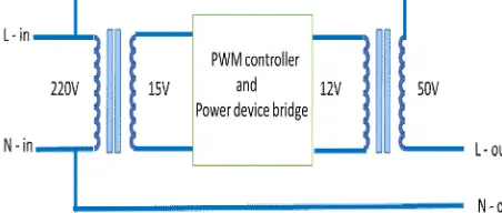
[image:1.612.188.414.618.714.2]Fig.1 indicates transformers employed to inject and control the line voltage to reach within standard limits. The line transformer is a step-down transformer powering up 15VAC in its secondary. This is power required to drive the next stage transformer is step up transformer from 12VAC to 50VAC. Power circuitry in between these transformers consists of a PWM controller operated at a fixed high frequency [2]. A power device wired around to switch the power path in both the directions to path the AC power between the two transformers. PWM pulses drive the power device to make and brake AC power flow between the secondary and primary of the coupling arrangement. PWM controller is configured to operate with a Turn ON and Turn OFF duty cycle of 0% to 100%. The power switched pulses are filtered to for a sine wave. A feedback from the load is sampled to the PWM controller which functions as a regulator [3]. PWM controller is driven with a microcontroller ported with fuzzy logic which makes the decision of pulse width from 0 to 100%. Fuzzy logic takes a single input which is output voltage across the load and derives pulse width percentage.
A. Fuzzy Logic
Sine weighted pulse width is ported out from the controller is applied on to a dedicated PWM controller with its switching frequency pulse widths correspond to sine wave. This train of pulses switch the power devices in the bridge to form a sine wave across AC load. A sample of output power is fed back to microcontroller to form a closed loop for regulating the power across the load. Fuzzy logic in the feedback loop plays a role in correction speed with accuracy. Correction factor is calculated and is applied on to the Vpwm, where V = Vpwm ( sine Θ ) which is considered to be 39 µSec without a control [1].
Sine wave signal Amplitude Feedback Amplitude SA – Small Amplitude SF – Small Amplitude MA – Medium Amplitude MF – Medium Amplitude LA – Large Amplitude LF – Large Amplitude {SA, MA, LA} {SF, MF, LF}
B. Correction Pulse Width
CVS – Very Small Width CS – Small Width CM – Medium Width CL – Large Width CVL – Very Large Width {CVS, CS, CM, CL, CVL}
Define range of Signal Amplitude and Feedback Amplitude, Membership Function of the input and output variables. We use Triangular Membership Functions.
Range for Signal Amplitude (0 to 5): Range for Feedback Amplitude (0 to 5): SA: 0 to 2.5 SF: 0 to 2.5
Membership function for Correction factor Voltage CVS: 0 to 9.75
CS: 0 to 19.5 CM: 9.75 to 29.25 CL: 19.5 to 39 CVL: 29.25 to 39
C. Rule Base For Correction Factor Voltage
Thus generated fuzzy logic decision in the form of a numerical value to alter the multiplication value Vpwm in V = Vpwm ( sine Θ )
III. PFCANDSINEWAVEGENERATION
Power Factor Corrector (PFC) is a module available in modular form. This can be used or a it could be formed using dedicated PFC controller devices and external magnetics. The power output from this module is regulated and trimmable to required voltage. Voltage of this is generally at 300 to 315V DC and to the rated power capacity by selection [2]. When it comes to 3 phase system a unique power factor corrector for an input voltage of 440V phase to phase needs to be designed. This is not a topic for the present paper.
Fig.2 PFC derived DC Over MOSFET Bridge for AC Power
Fig.2 indicates sections to regulate and convert AC variation from 170VAC to 300VAC to a constant 220VAC. Power ratings of each section and components can be decided depending on the current drawn from the load. The digital section bearing a microcontroller runs fuzzy logic and ports out sine wave to switch the MOSFET Bridge [1]. This runs a single-phase system. Three such with synchronisation can run three phase system.
Fig.3 Microcontroller porting out SPWM with Fuzzy Logic in Feedback and control
Fig.3 indicates a microcontroller deriving regulated Sine wave and Triangular wave to develop SPWM. The Digital part delivers SPWM pulses to link a drive to the MOSFET Bridge through an opt isolator. The software part of the controller runs a calculation, fuzzy logic decision from the feedback to deliver the height of the amplitude of sine wave [1]. Calculations are as below.
V = Vm ( sine Θ )
Were
V is voltage corresponding to weight of Sine Vm is Maximum operating voltage
sine Θ is the angle at which its weighted voltage to be derived
256 values from 0° to 180° are calculated. Each part angle Θ = 180°/ 256 = 0.703125° Maximum amplitude of the waveform Vm = 5V Amplitude at Θ = 0.703125° will be V = Vm ( sine Θ ) V = 5 ( sine 0.703125 )
V = 5(0.01249) V = 0.06245 V
5V max corresponds to HEX value 0FFH
0.06245V corresponds to HEX data = ( 0.06245 X 256 ) / 5 = 3.1974
= 003H
Microcontroller ports out each of this data in less than 25µSec off 39µSec of allotted time for one off 256 steps in 10mSec of time for one ½ cycle of 50Hz of frequency.
A. Fuzzy Logic
Sine weighted data with hex values is ported out from the microcontroller and Digital to Analogue converted where each value contributes to construct half sine wave. This is processed to switch power devices and power ported out to the load. A sample of this power is fed back to controller to form a closed loop for regulating the power across the load. Fuzzy logic in the microcontroller reads the feedback voltage and generates a correction factor and is applied on to the Vm, where V = Vm ( sine Θ ) which is considered to be 5V without a control [1]. This takes less than 12 µSec complying to the requirement and able to perform within 39 µSec.
Sine wave signal Amplitude Feedback Amplitude PSA – Small Amplitude PSF – Small Amplitude PMA – Medium Amplitude PMF – Medium Amplitude PLA – Large Amplitude PLF – Large Amplitude {PSA, PMA, PLA} {PSF, PMF, PLF}
Correction Pulse Width: PVS – Very Small Control PS – Small Control PM – Medium Control PL – Large Control PVL – Very Large Control {PVS, PS, PM, PL, PVL}
Define range of Signal Amplitude and Feedback Amplitude, Membership Function of the input and output variables. We use Triangular Membership Functions.
Range for Signal Amplitude (0 to 5): Range for Feedback Amplitude (0 to 5): PSA: 0 to 2.5 PSF: 0 to 2.5
Membership function for Correction factor Voltage: PVS: 0 to 2
PS: 0 to 3 PM: 2 to 4 PL: 3 to 5 PVL: 4 to 5
B. Rule Base For Correction Factor Voltage
Thus generated fuzzy logic decision in the form of a numerical value to alter the multiplication value Vm in V = Vm ( sine Θ )
IV. CONCLUSION
This system makes it compact since it bears less magnetics compared to the conventional methods [5]. It generates no brushing sounds since there are no moving parts. Weight of this system reduces drastically and hence durability increases. It is compact and rugged which promises military standards with care on EMI and RFI exclusively. Finally efficiency is very high compared to any other systems of the kind.
REFERENCES
[1] Simplified Digital Waves And Sinusoidal Pulse Width Modulation For Single Phase Inverter P.Chow Reddy, P.Surya Narayana Reddy, INTERNATIONAL JOURNAL OF MULTIDISCIPLINARY EDUCATIONAL RESEARCH, ISSN: 2277-7881; IMPACT FACTOR – 6.014; IC VALUE:5.16; ISI VALUE:2.286, VOLUME 8, ISSUE 5(3), MAY 2019
[2] Muhammad H. Rashid, “Power electronics: circuits, devices, and applications”, 3rd ed. 2004, Pearson/Prentice Hall. (Book).
[3] Study of Solid State Static Voltage StabilizerUsing Buck-Boost Converter, Dr.Rajendra Sawant1, Kshitija Sawant2, Laxmi Kanojia3, Priyanka Samgiskar4, Vishakha Nevarekar5, International Journal of Innovative Research in Science,Engineering and Technology, ISSN(Online) : 2319-8753 ISSN (Print) : 2347-6710, Vol. 5, Issue 12, December 2016
[4] A Novel Simple Reliability Enhancement SwitchingTopology for Single Phase Buck-Boost Inverter, International Journal of Engineering Development and Research, Snehal Balaji Gatkine, IJEDR 2018, Volume 6, Issue 2, ISSN: 2321-9939