2569
©IJRASET: All Rights are Reserved
Seismic Analysis of different Shaped Building
Structures using ETABS
Vikas Jain
1, Prof. Hitesh Kodwani
21MTech Scholar, Sam College of Engineering and Technology, Bhopal 2Assistant Professor, Sam College of Engineering and Technology, Bhopal
Abstract: Due to the unpredictable nature of Earthquake, it is necessary to design the tall structures by considering the critical effects of earthquake on the structure. Earthquake force depends upon exposed area of the structure. The Earthquake force depends upon size and shape of structure so it is very important to consider fluctuating component of earthquake pressure while designing the structure. The performance of a structure can be improved when an earthquake acts by improving the shape of the structure by providing different configurations so that the earthquake load will be less. In this research, an attempt is made to compare different shapes of structure like T, H, E and L are considered with a G+15 story structure in seismic zone IV on ETABS software using response spectrum method. The parameters on which the research is based are Maximum Storey Displacement, Maximum Overturning Moment and Maximum Auto Lateral Loads.
Keywords: Tall buildings, Earthquake force, Seismic zone, Storey displacement, Auto lateral force, ETABS
I. INTRODUCTION
Resent advances in the development of high strength materials coupled with more advanced computational methods and design procedures have led to a new generation of tall buildings which are slender and light. These buildings are very sensitive to the two common dynamic loads as wind and earthquakes. The Earthquake force depends upon size and shape of structure so it is very important to consider fluctuating component of earthquake pressure while designing the structure. The performance of a structure can be improved when an earthquake acts by improving the shape of the structure by providing different configurations so that the earthquake load will be less. For performing the seismic analysis of a structure, the actual time history record of each and every location is necessary.
Though, it is not possible to get all records or data at each and every location. Furthermore, the seismic analysis of structures cannot be carried out simply based on the peak value of the ground acceleration as the response of the structure depend upon the recurrence substance of ground movement and its own unique properties.
To defeat the above challenges, tremor reaction range is the most well-known instrument in the seismic examination of structures. There are computational preferences in utilizing the reaction range strategy for seismic examination for expectation of removals and part powers in basic frameworks.
The method consists of the calculation of only the maximum values of the displacements and member forces in each mode of vibration using smooth design spectra that are the average of several earthquake motions. Reaction spectra are bends plotted between most extreme reaction of SDOF framework exposed to determined seismic tremor ground movement. Reaction range can be deciphered as the locus of most extreme reaction of a SDOF framework. Reaction range investigation (RSA) is a straight powerful measurable examination technique. Reaction range investigation is helpful for plan basic leadership since it relates auxiliary sort determination to dynamic execution.
1) Objective: The main objective of this work is to do the comparative study of seismic analysis of high-rise structure having different configurations in seismic zone IV of India. The same structure is analysed by ETABS software.
These are the following objectives of this work-
a) To study the Maximum Storey Displacement and Maximum Overturning Moments and Maximum Auto Lateral Loads on high-rise structure with different Configurations.
b) To suggest the sustainability of configuration of the structure in seismic zone IV.
2570
©IJRASET: All Rights are Reserved
1) G. R. Patil (et al 2015), talked about the advancement of new engineering types of structures and adaptable basic frameworks are defenseless against wind activity. For alluring execution of these structures, we require better comprehension of connection among building and wind. Structures are delegated unbending and adaptable. This paper displays a relative investigation of impact of wind on plans with various sporadic shapes as I, C, T and L. The noteworthiness of this work is to assess the plan heap of the structure exposed to twist in a specific area. The breeze load is evaluated dependent on fundamental breeze speed and different factors as kind of geology, territory, and the utilization of building and its hazard factor for that specific area. The present examination manages the computation of wind loads for basic edge with various arrangement shapes and the outcomes are contrasted with deference with passable floats of individual structures. In this investigation it is discovered that the measure of float is significantly changed as for state of the structure. And furthermore discovered that breeze load on the building is most extreme when it has greatest uncovered territory.
2) Dr.K.Muthumani (et al 2016), Studied that in 1930s'many tall structures were built over the world. It was a time of incredible success for elevated structures as broad research work was done on wind instigated impacts on tall structures. Not at all like the mean stream of wind, which can be considered as static, wind loads related with windiness or choppiness quickly and even suddenly, making impacts a lot bigger than if similar burdens were connected bit by bit. Wind loads, in this manner, should be considered asif they were dynamic in nature. CFD examination turns into the most well known for such wind actuated reaction considers. This examination is fundamentally focus on wind instigated weights which would be emerges because of wind power and how weight fluctuates as indicated by various states of structures. The power of a breeze load relies upon how quick it changes and furthermore on the reaction of structure. Ansys Fluent has been utilized for CFD investigations to think about the breeze instigated reaction.
3) MD. MAHMUD SAZZAD (2015), contemplated that With the expansion in the use of present day advances in Civil Engineering, development of elevated structures is expanding very quickly. Such structures are inclined to horizontal burdens from wind or seismic tremor. Various methodologies have been embraced to limit the extreme impacts of horizontal loads on the tall structures. State of building is one of such methodologies. This paper exhibits a numerical investigation of the impact of building shape on the reaction to wind and quake. Three distinct states of structures have been considered in the present examination and a correlation between various formed of structures against the impact of horizontal loads because of wind and seismic tremor has been displayed. PC helped investigation has been done to play out the relative examination and center the impact of the state of building. The Bangladesh National Building Code (BNBC), 2006 has been considered in the investigation. The outcome portrays that the state of building has detectable impact in limiting the float of building.
III. METHODOLOGY
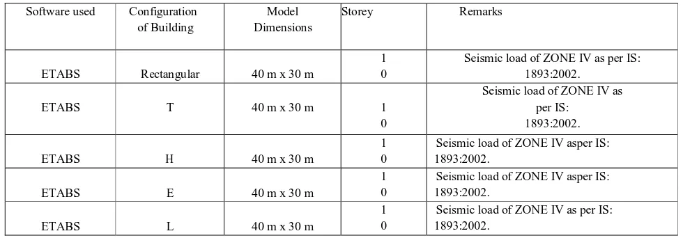
[image:2.595.53.543.570.741.2]In this research work, the analysis based on linear static method is used to investigate DIFFERENT SHAPES STRUCTURES under seismic parameters as per IS-standards. In order to study the seismic severity of different shapes structures, zone 4 is considered of India.
Table 1: BUILDING MODEL
Software used Configuration
of Building
Model Dimensions
Storey Remarks
ETABS Rectangular 40 m x 30 m
1 0
Seismic load of ZONE IV as per IS: 1893:2002.
ETABS T 40 m x 30 m 1
0
Seismic load of ZONE IV as per IS:
1893:2002.
ETABS H 40 m x 30 m
1 0
Seismic load of ZONE IV asper IS: 1893:2002.
ETABS E 40 m x 30 m
1 0
Seismic load of ZONE IV asper IS: 1893:2002.
ETABS L 40 m x 30 m
1 0
2571
©IJRASET: All Rights are Reserved
Fig.1: Different Plans Table 2: Specifications
Specifications Data
Typical Story Height 3.5 m Base Story Height 1.5 m No. of Bays in X-Direction 8 No. of Bays in Y-Direction 6 Bay Length in X-Direction 5 m Bay Length in Y-Direction 5 m
Concrete Grade M-35
Density of R.C.C. 25 kN/m3 Density of Masonry 20 kN/m3
Columns 350 mm x 500 mm
Beams 300 mm x 350 mm
Slab Thickness 120 mm Bottom Support Conditions Fixed
Live
Load- Roof Rest of the structure
1
kN/m22
kN/m2Soil Conditions Medium Soil (Type II) Damping Ratio 5%, as per IS-1893: 2002 (Part-1)
Poisson Ratio 0.2
Response Reduction Factor 3
Importance Factor 1
Zone Factor As per IS-1893: 2002 (Part-1) for
2572
©IJRASET: All Rights are Reserved
Maximum Storey Displacement in respective
directions
80 75 70 65 60 55
73.05 70.96 74.75 74.89
65.61 63.46 63.36 66.19
Maximum Storey Displacement in X Maximum Storey Displacement in Y
direction direction
T H E L
1) Self-weight of slab considering 120 mm thickness = 0.12 x 25 = 3.0 kN/m2 2) Masonry Full Exterior wall load = 0.2 x 3.15 x 20 = 12.6 kN/m
3) Masonry Full Interior wall load = 0.1 x 3.15 x 20 = 6.3 kN/m 4) Masonry Roof wall load = 0.2 x 1 x 20 = 4 kN/m
B. Flow Chart Of The Study
IV. RESULTS AND DISCUSSIONS
2573
©IJRASET: All Rights are Reserved
Maximum Overturning Moments in X Maximum Overturning Moments in Y
direction direction
T H E L
46770.3 46070.03 38411.42
55994.14 51512.79
52149.56 35420.51
64745.39
80000 60000 40000 20000 0
Maximum Overturning Moments in respective
directions
300 250 200 150
100
50 0
Maximum Auto Lateral Loads in respective
directions
285.55
249.74
234.79 235.82
209.11 207.85
160.59 172.82
Maximum Auto Lateral Loads in X direction
Maximum Auto Lateral Loads in Y direction
T H E L
Fig.3: Maximum Overturning Moments
Fig.4: Maximum Auto Lateral Loads
V. CONCLUSIONS
A. With the change in shape of building such as H, T, E, L the maximum storey displacement increases this is because the distribution of seismic force depends on the relative stiffness of the lateral frames.
B. Thus, on the basis of maximum storey displacement H shaped building has lesser storey displacements as compared to T, H, E and L shaped building because it is maximum in L and minimum in H.
C. With the change in shape of building such as E, H, L, T the maximum overturning moments decreases for T shape building and increases E shape building.
D. Thus, on the basis of maximum overturning moment, T shaped building shows minimum overturning moment values as compared to all other shapes because overturning moment depends upon
E. With the change in shape of building such as T, H, E, L the maximum Auto lateral loads decreases for T shape building and increases for E shape building.
F. Thus, on the basis of Auto lateral loads, T shaped building shows minimum overturning moment values as compared to all other shapes because the auto lateral forces depend up the mass of the structure and amongst all the structures
2574
©IJRASET: All Rights are Reserved
A. In this study, fixed supports are considered for the analysis of the structure. In the future, it can be extended for different support conditions.
B. This study was done using T, H, E and L shapes only further other shapes can be used for the analysis.
C. This analysis was done using ETABS software further this could be done using various different available software also.
D. In future, this work can also be done while considering different soil types along with different seismic zones.
E. This study is prepared for response spectrum analysis of structure, it can be extended further for time history analysis also.
REFERENCES
[1] B. S. Mashalkar, G. R. Patil, and A. S. Jadhav, “Effect of Plan Shapes on the Response of Buildings Subjected To Wind Vibrations,” Iosr-Jmce, vol. 1, pp. 80– 89, 2015.
[2] C. August, P. No, G. Kostantakopoulos, and S. Bousias, “13 th World Conference on Earthquake Engineering EXPERIMENTAL STUDY OF THE EFFECT OF REINFORCEMENT,” no. 770, 2004.
[3] R. Kulkarni, “Shape Effects on Wind Induced Response of Tall Buildings Using CFD,” Ijirset, vol. 5, no. 3, pp. 2830–2836, 2016. [4] A. Ullas and P. Nimisha, “Response of Buildings of Different Plan Shapes Subjected To Wind Vibrations,” pp. 1625–1628, 2017.
[5] A. A. N. Al-aghbari, S. H. Hamzah, N. H. A. Hamid, and N. A. Rahman, “Structural performance of two types of wall slab connection under out-of-plane lateral cyclic loading,” J. Eng. Sci. Technol., vol. 7, no. 2, pp. 177–194, 2012.
[6] B. Khafaf, R. Mirghaderi, A. Imanpour, and F. Kheshavarz, “Behavior of Torsional Effects of Asymmetric Pyramid Shape High Rise Building in Seismic Zone,” Struct. Congr. 2008, vol. 41016, no. October, pp. 1–9, 2008.
[7] A. Hamada and A. El Damatty, “Seismic analysis of L-shaped high and low rise buildings-comparison with NBCC 2005 and NBCC 2010 Seismic Analysis of L-Shaped High and Low Rise Buildings – Comparison with NBCC 2005 and NBCC 2010,” no. May, 2013.
[8] IS 456, “IS 456: 2000 - Plain and reinforced concrete - code and practice,” Bur. Indian Stand., p. 144, 2000. [9] IS:800, “General construction in steel-code of practice,” no. December, 2007.